1995 ACURA TL ESP
[x] Cancel search: ESPPage 883 of 1771
Idle Control System
System Description
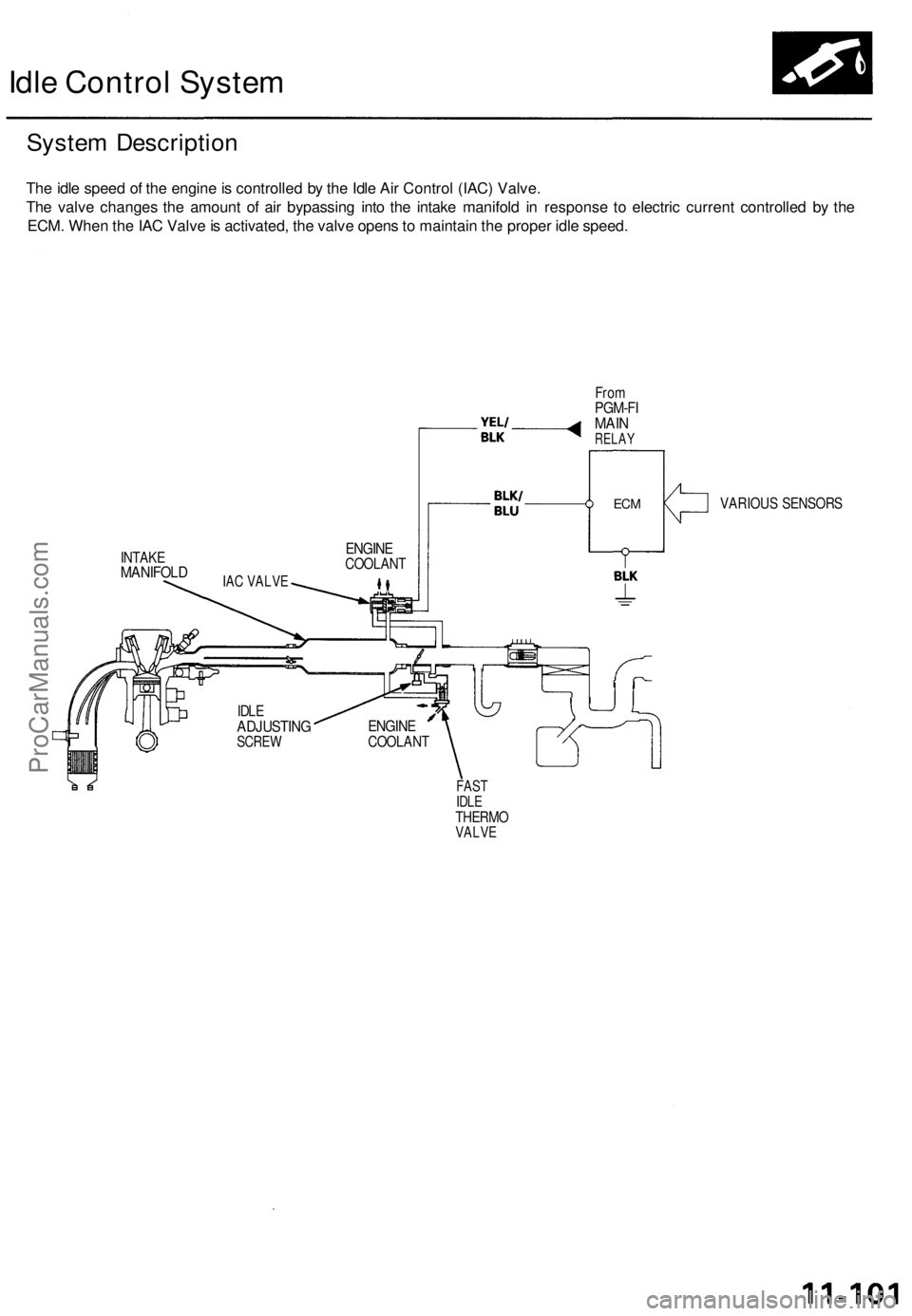
The idle speed of the engine is controlled by the Idle Air Control (IAC) Valve.
The valve changes the amount of air bypassing into the intake manifold in response to electric current controlled by the
ECM. When the IAC Valve is activated, the valve opens to maintain the proper idle speed.
From
PGM-FI
MAIN
RELAY
INTAKE
MANIFOLD
VARIOUS SENSORS
FAST
IDLE
THERMO
VALVE
IDLE
ADJUSTING
SCREW
ENGINE
COOLANT
ENGINE
COOLANT
IAC VALVE
ECMProCarManuals.com
Page 936 of 1771

Description
The automatic transmission is a combination of a 3-element torque converter and a dual-shaft electronically controlled
automatic transmission which provides 4 speeds forward and 1 reverse. The entire unit is positioned in line with the engine.
Torque Converter, Gears and Clutches
The torque converter consists of a pump, turbine and stator, assembled in a single unit.
They are connected to the engine crankshaft so they turn together as a unit as the engine turns.
Around the outside of the drive plate is a ring gear which meshes with the starter pinion when the engine is being started.
The entire torque converter assembly serves as a flywheel while transmitting power to the transmission mainshaft.
The transmission has two parallel shafts: the mainshaft and the countershaft. The mainshaft is in line with the engine
crankshaft.
The mainshaft includes the 1st, 2nd and 4th clutches, and gears for 4th, 2nd, 1st and reverse (3rd gear is integral with the
mainshaft, while the reverse gear is integral with 4th gear).
The countershaft includes the 3rd, and 1st-hold clutches, and gears for 3rd, 4th, 1st, 2nd, reverse, and parking. The sec-
ondary drive gear is integrated with the countershaft.
The gears on the mainshaft are in constant mesh with those on the countershaft.
When certain combinations of gears in the transmission are engaged by clutches, power is transmitted from the mainshaft
to the countershaft to provide and positions.
Electronic Control
The electronic control system consists of the Transmission Control Module (TCM), sensors, a linear solenoid and four
solenoid valves. Shifting and lock-up are electronically controlled for comfortable driving under all conditions.
The TCM is located below the dashboard, behind the glove box on the passenger's side.
Hydraulic Control
The lower valve body assembly includes the main valve body, the servo body and the shift control solenoid valves. They
are bolted on the lower part of the transmission housing.
Other valve bodies, the regulator valve body, the ATF pump body, the 2nd accumulator body, and the throttle valve body,
are bolted to the torque converter housing.
The main valve body contains the manual valve, the 1 - 2 shift valve, the 2 - 3 shift valve, the 3 - 4 shift valve, the 4th kick-
down valve, the 2 - 3 orifice control valve, the 3 - 4 orifice control valve, the 4th exhaust valve, the servo control valve,
and the main orifice control valve.
The servo body contains the servo valve, 3rd and 4th accumulator pistons.
The regulator valve body contains the regulator valve, the lock-up shift valve, and the cooler relief valve.
Fluid from the regulator passes through the manual valve to the various control valves.
The throttle valve body includes the throttle valve which is bolted onto the 2nd accumulator body. The 2nd accumulator
piston is assembled in the 2nd accumulator body.
The linear solenoid is joined with the throttle valve body.
The ATF pump body contains the modulator valve, the lock-up control valve, the lock-up timing valve, and the relief valve.
The torque converter check valve is located in the torque converter housing under the ATF pump body.
The 1st and 1st-hold accumulator pistons are assembled in the rear cover.
The clutches receive fluid from their respective feed pipes or internal hydraulic circuit.
Shift Control Mechanism
Input from various sensors located throughout the vehicle determines which shift control solenoid valve the TCM will acti-
vate. Activating a shift control solenoid valve changes modulator pressure, causing a shift valve to move. This pressurizes
a line to one of the clutches, engaging that clutch and its corresponding gear.
Lock-up Mechanism
In position, in 2nd, 3rd and 4th, and in position in 3rd, pressurized fluid is drained from the back of the torque con-
verter through a fluid passage, causing the lock-up piston to be held against the torque converter cover. As this takes place,
the mainshaft rotates at the same speed as the engine crankshaft. Together with hydraulic control, the TCM optimizes the
timing of the lock-up mechanism. The lock-up valves control the range of lock-up according to lock-up control solenoid
valves A and B, and throttle valve. When lock-up control solenoid valves A and B activate, the modulator pressure changes.
The lock-up control solenoid valves A and B are mounted on the torque converter housing, and are controlled by the TCM.ProCarManuals.com
Page 954 of 1771
Ascending Control
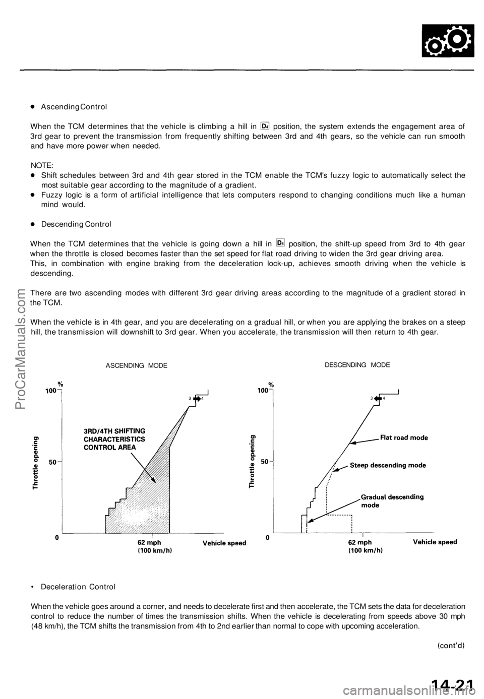
When the TCM determines that the vehicle is climbing a hill in position, the system extends the engagement area of
3rd gear to prevent the transmission from frequently shifting between 3rd and 4th gears, so the vehicle can run smooth
and have more power when needed.
NOTE:
Shift schedules between 3rd and 4th gear stored in the TCM enable the TCM's fuzzy logic to automatically select the
most suitable gear according to the magnitude of a gradient.
Fuzzy logic is a form of artificial intelligence that lets computers respond to changing conditions much like a human
mind would.
Descending Control
When the TCM determines that the vehicle is going down a hill in position, the shift-up speed from 3rd to 4th gear
when the throttle is closed becomes faster than the set speed for flat road driving to widen the 3rd gear driving area.
This, in combination with engine braking from the deceleration lock-up, achieves smooth driving when the vehicle is
descending.
There are two ascending modes with different 3rd gear driving areas according to the magnitude of a gradient stored in
the
TCM.
When the vehicle is in 4th gear, and you are decelerating on a gradual hill, or when you are applying the brakes on a steep
hill, the transmission will downshift to 3rd gear. When you accelerate, the transmission will then return to 4th gear.
ASCENDING MODE
DESCENDING MODE
• Deceleration Control
When the vehicle goes around a corner, and needs to decelerate first and then accelerate, the TCM sets the data for deceleration
control to reduce the number of times the transmission shifts. When the vehicle is decelerating from speeds above 30 mph
(48 km/h), the TCM shifts the transmission from 4th to 2nd earlier than normal to cope with upcoming acceleration.ProCarManuals.com
Page 997 of 1771
Pressure Testin g
While testing , b e carefu l o f th e rotatin g fron t wheels .
Mak e sur e lifts , jack s an d safet y stand s ar e place d
properl y (se e sectio n 1 ).
CAUTION :
Befor e testing , b e sur e th e transmissio n flui d is fille d
t o th e prope r level .
War m u p th e engin e befor e testing .
1. Rais e th e fron t o f th e vehicle , an d suppor t i t wit h
safet y stand s (se e sectio n 1 ).
2 . Se t th e parkin g brake , an d bloc k bot h rea r wheel s
securely .
3. Allo w th e fron t wheel s t o rotat e freely .
4 . War m u p th e engin e (th e radiato r fa n come s on) ,
the n sto p an d connec t a tachometer .
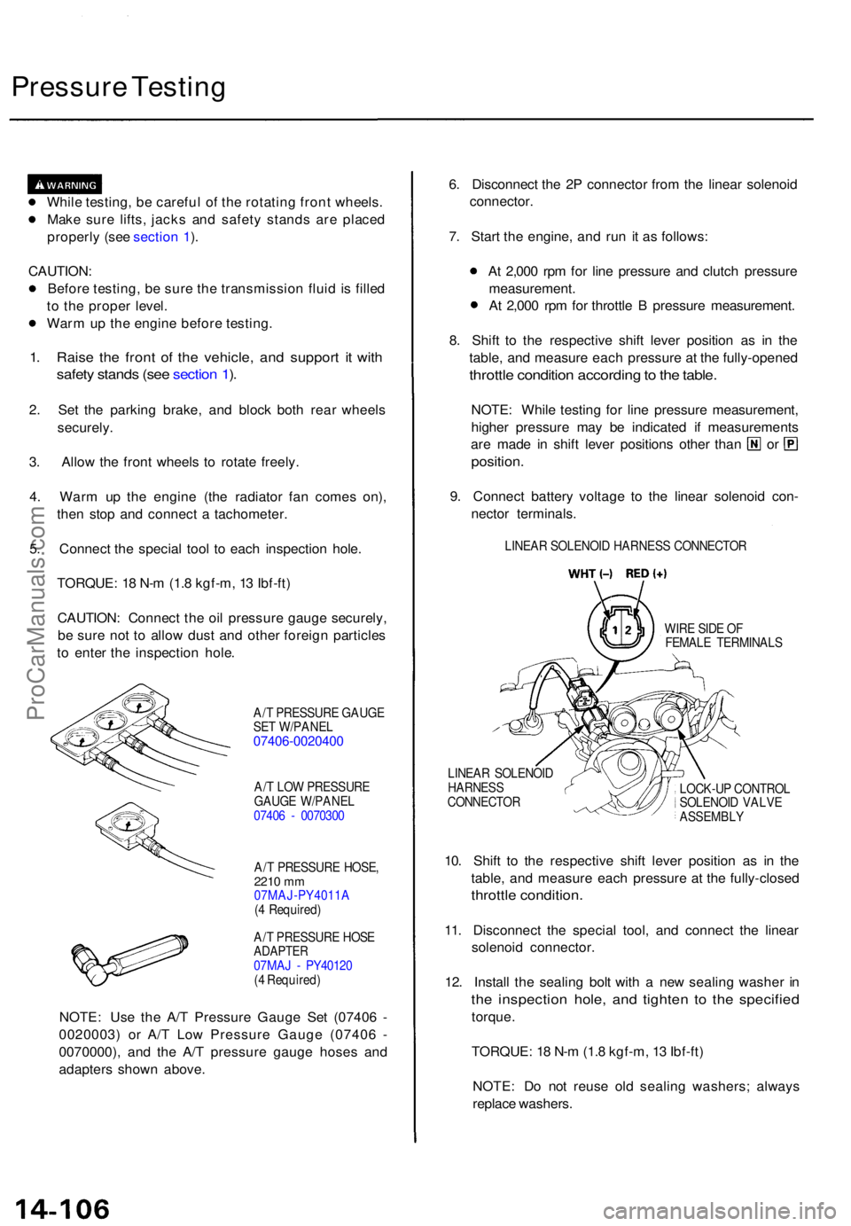
5 . Connec t th e specia l too l t o eac h inspectio n hole .
TORQUE : 1 8 N- m (1. 8 kgf-m , 1 3 Ibf-ft )
CAUTION : Connec t th e oi l pressur e gaug e securely ,
b e sur e no t t o allo w dus t an d othe r foreig n particle s
t o ente r th e inspectio n hole .
A/T PRESSUR E GAUG E
SE T W/PANE L
07406-002040 0
A/T LO W PRESSUR E
GAUG E W/PANE L
0740 6 - 007030 0
A/ T PRESSUR E HOSE ,
2210 mm07MAJ-PY4011 A
( 4 Required )
A/ T PRESSUR E HOS E
ADAPTE R07MAJ - PY4012 0
( 4 Required )
NOTE: Us e th e A/ T Pressur e Gaug e Se t (0740 6 -
0020003 ) o r A/ T Lo w Pressur e Gaug e (0740 6 -
0070000) , an d th e A/ T pressur e gaug e hose s an d
adapter s show n above . 6
. Disconnec t th e 2 P connecto r fro m th e linea r solenoi d
connector .
7 . Star t th e engine , an d ru n i t a s follows :
A t 2,00 0 rp m fo r lin e pressur e an d clutc h pressur e
measurement .
A t 2,00 0 rp m fo r throttl e B pressur e measurement .
8 . Shif t t o th e respectiv e shif t leve r positio n a s i n th e
table , an d measur e eac h pressur e a t th e fully-opene d
throttle conditio n accordin g to th e table .
NOTE : Whil e testin g fo r lin e pressur e measurement ,
highe r pressur e ma y b e indicate d i f measurement s
are mad e i n shif t leve r position s othe r tha n o r
position .
9. Connec t batter y voltag e t o th e linea r solenoi d con -
necto r terminals .
LINEAR SOLENOI D HARNES S CONNECTO R
WIR E SID E O F
FEMAL E TERMINAL S
LINEA R SOLENOI D
HARNES S
CONNECTO R LOCK-U
P CONTRO L
SOLENOI D VALV E
ASSEMBL Y
10. Shif t t o th e respectiv e shif t leve r positio n a s i n th e
table , an d measur e eac h pressur e a t th e fully-close d
throttle condition .
11. Disconnec t th e specia l tool , an d connec t th e linea r
solenoi d connector .
12 . Instal l th e sealin g bol t wit h a ne w sealin g washe r i n
th e inspectio n hole , an d tighte n t o th e specifie d
torque.
TORQUE : 1 8 N- m (1. 8 kgf-m , 1 3 Ibf-ft )
NOTE : D o no t reus e ol d sealin g washers ; alway s
replac e washers .
ProCarManuals.com
Page 1146 of 1771
Steering Pum p
Constructio n
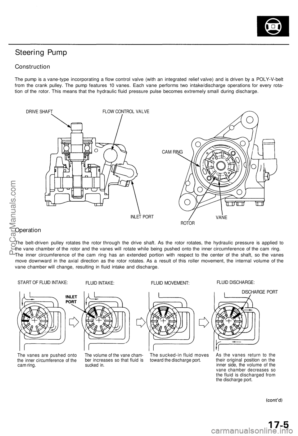
The pum p is a vane-typ e incorporatin g a flo w contro l valv e (wit h a n integrate d relie f valve ) an d i s drive n b y a POLY-V-bel t
fro m th e cran k pulley . Th e pum p feature s 1 0 vanes . Eac h van e perform s tw o intake/discharg e operation s fo r ever y rota -
tio n o f th e rotor . Thi s mean s tha t th e hydrauli c flui d pressur e puls e become s extremel y smal l durin g discharge .
DRIVE SHAF TFLOW CONTRO L VALV E
CAM RIN G
INLE T POR TVANE
ROTO R
Operatio n
The belt-drive n pulle y rotate s th e roto r throug h th e driv e shaft . A s th e roto r rotates , th e hydrauli c pressur e i s applie d t o
th e van e chambe r o f th e roto r an d th e vane s wil l rotat e whil e bein g pushe d ont o th e inne r circumferenc e o f th e ca m ring .
Th e inne r circumferenc e o f th e ca m rin g ha s a n extende d portio n wit h respec t t o th e cente r o f th e shaft , s o th e vane s
mov e downwar d i n th e axia l directio n a s th e roto r rotates . A s a resul t o f thi s rolle r movement , th e interna l volum e o f th e
van e chambe r wil l change , resultin g i n flui d intak e an d discharge .
START O F FLUI D INTAKE :FLUID INTAKE :FLUID MOVEMENT :FLUID DISCHARGE :
DISCHARGE POR T
The vane s ar e pushe d ont othe inne r circumferenc e o f th ecam ring .
The volum e o f th e van e cham -ber increase s s o tha t flui d i ssucke d in .
Th e sucked-i n flui d move stoward th e discharg e port .As th e vane s retur n t o th ethei r origina l positio n o n th einne r side , th e volum e o f th evan e chambe r decrease s s othe flui d i s discharge d fro mthe discharg e port .
ProCarManuals.com
Page 1179 of 1771
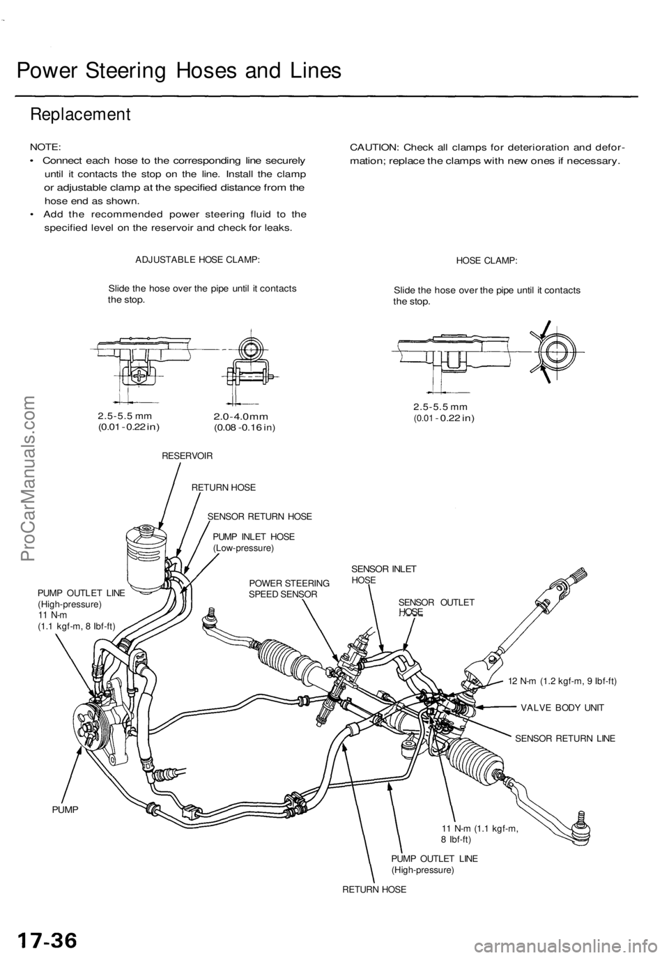
Power Steering Hoses and Lines
Replacement
NOTE:
• Connect each hose to the corresponding line securely
until it contacts the stop on the line. Install the clamp
or adjustable clamp at the specified distance from the
hose end as shown.
• Add the recommended power steering fluid to the
specified level on the reservoir and check for leaks.
CAUTION: Check all clamps for deterioration and defor-
mation; replace the clamps with new ones if necessary.
ADJUSTABLE HOSE CLAMP:
HOSE CLAMP:
Slide the hose over the pipe until it contacts
the stop.
Slide the hose over the pipe until it contacts
the stop.
2.5-5.5 mm
(0.01
-
0.22
in)
2.0
-
4.0
mm
(0.08 -0.16
in)
2.5-5.5 mm
(0.01
-
0.22
in)
RESERVOIR
PUMP OUTLET LINE
(High-pressure)
11 N-m
(1.1 kgf-m, 8 Ibf-ft)
12 N-m (1.2 kgf-m, 9 Ibf-ft)
VALVE BODY UNIT
SENSOR RETURN LINE
PUMP
PUMP OUTLET LINE
(High-pressure)
RETURN HOSE
11 N-m (1.1 kgf-m,
8 Ibf-ft)
SENSOR OUTLET
HOSE
SENSOR INLET
HOSE
POWER STEERING
SPEED SENSOR
PUMP INLET HOSE
(Low-pressure)
SENSOR RETURN HOSE
RETURN HOSEProCarManuals.com
Page 1201 of 1771
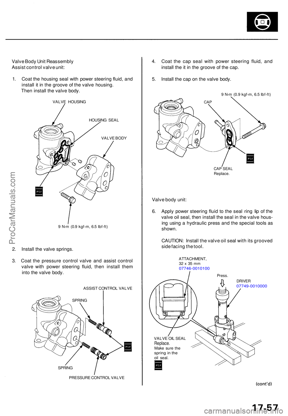
Valve Bod y Uni t Reassembl y
Assis t contro l valv e unit :
1 . Coa t th e housin g sea l wit h powe r steerin g fluid , an d
instal l i t i n th e groov e o f th e valv e housing .
The n instal l th e valv e body .
VALV E HOUSIN G
HOUSIN G SEA L
VALV E BOD Y
9 N- m (0. 9 kgf-m , 6. 5 Ibf-ft )
2. Instal l th e valv e springs .
3 . Coa t th e pressur e contro l valv e an d assis t contro l
valv e wit h powe r steerin g fluid , the n instal l the m
int o th e valv e body .
ASSIS T CONTRO L VALV E
PRESSUR E CONTRO L VALV E
4. Coa t th e ca p sea l wit h powe r steerin g fluid , an d
instal l th e it i n th e groov e o f th e cap .
5 . Instal l th e ca p o n th e valv e body .
9 N- m (0. 9 kgf-m , 6. 5 Ibf-ft )
CAP SEA LReplace .
Valve bod y unit :
6 . Appl y powe r steerin g flui d t o th e sea l rin g li p o f th e
valv e oi l seal , the n instal l th e sea l i n th e valv e hous -
in g usin g a hydrauli c press and th e specia l tool s a s
shown .
CAUTION : Instal l th e valv e oi l sea l wit h it s groove d
sid e facin g th e tool .
ATTACHMENT ,32 x 35 m m07746-001010 0
Press.
DRIVE R07749-001000 0
VALVE OI L SEA LReplace .Make sur e th esprin g in th eoil seal .
CAP
SPRIN G
SPRIN G
ProCarManuals.com
Page 1205 of 1771
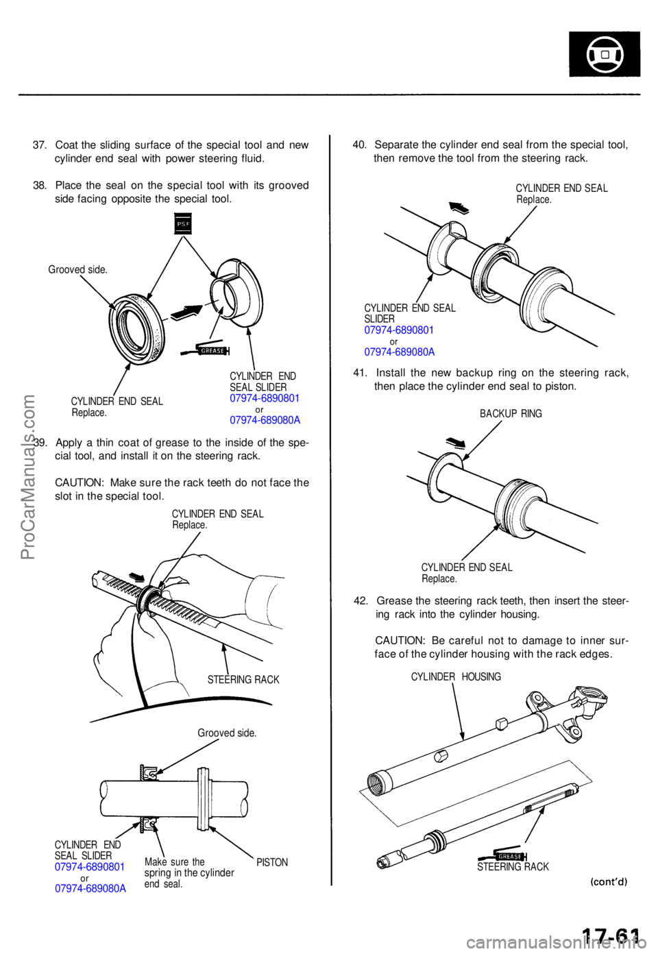
37. Coa t th e slidin g surfac e o f th e specia l too l an d ne w
cylinde r en d sea l wit h powe r steerin g fluid .
38 . Plac e th e sea l o n th e specia l too l wit h it s groove d
sid e facin g opposit e th e specia l tool .
Groove d side .
CYLINDE R EN D SEA L
Replace . CYLINDE
R EN D
SEA L SLIDE R07974-689080 1or07974-689080 A
39. Appl y a thi n coa t o f greas e t o th e insid e o f th e spe -
cia l tool , an d instal l i t o n th e steerin g rack .
CAUTION : Mak e sur e th e rac k teet h d o no t fac e th e
slo t i n th e specia l tool .
CYLINDE R EN D SEA L
Replace .
CYLINDE R EN D
SEA L SLIDE R
07974-689080 1or07974-689080 A
Make sur e th esprin g in th e cylinde rend seal .
40. Separat e th e cylinde r en d sea l fro m th e specia l tool ,
the n remov e th e too l fro m th e steerin g rack .
CYLINDE R EN D SEA LReplace .
CYLINDE R EN D SEA L
SLIDE R
07974-689080 1or07974-689080 A
41. Instal l th e ne w backu p rin g o n th e steerin g rack ,
the n plac e th e cylinde r en d sea l t o piston .
BACKU P RIN G
CYLINDE R EN D SEA L
Replace .
42. Greas e th e steerin g rac k teeth , the n inser t th e steer -
in g rac k int o th e cylinde r housing .
CAUTION : B e carefu l no t t o damag e t o inne r sur -
fac e o f th e cylinde r housin g wit h th e rac k edges .
CYLINDE R HOUSIN G
STEERIN G RAC K
Groove d side .
STEERIN G RAC K
PISTO N
ProCarManuals.com