Page 572 of 1771
A/C System Service
Charging
Use only service equipment that is U.L.-listed and is cer-
tified to meet the requirements of SAE J2210 to remove
HFC-134a (R-134a) from the air conditioner system.
CAUTION: Exposure to air conditioner refrigerant and
lubricant vapor or mist can irritate eyes, nose and throat.
Avoid breathing the air conditioner refrigerant and lubri-
cant vapor or mist.
If accidental system discharge occurs, ventilate work
area before resuming service. Additional health and
safety information may be obtained from the refrigerant
and lubricant manufacturers.
Refrigerant capacity: 750 g (26.5 oz)
CAUTION: Do not overcharge the system; the compressor
will be damaged.
Connect a R-134a refrigerant Recovery/Recycling/Charging
System to the vehicle, as shown, following the equipment
manufacturer's instructions.
Recovery/Recycling/Charging System
HIGH-PRESSURE
SIDE
LOW-PRESSURE
SIDEProCarManuals.com
Page 581 of 1771
Power Relay s
Relay Tes t
NOTE : Refe r t o page 23-62 in the '9 5 - 9 6 Acur a 2.5T L
Service Manual, P/ N 61SW500 , fo r th e item s no t shown
in this sub-section .
Normally-ope n type :
1 . Chec k fo r continuit y betwee n th e terminals .
• Ther e shoul d b e continuit y betwee n th e No . 1 an d
No . 3 terminal s whe n powe r an d groun d ar e con -
necte d to th e No . 2 an d No . 4 terminals .
• Ther e shoul d b e n o continuit y betwee n th e No . 1
an d No . 3 terminal s whe n powe r i s disconnected .
• Powe r windo w rela y
• Blowe r moto r rela y
• Windshiel d wipe r rela y
• Tailligh t rela y •
A/ T revers e rela y
• Sea t heate r rela y
• TC S fail-saf e rela y
• Fo g ligh t rela y
ProCarManuals.com
Page 596 of 1771

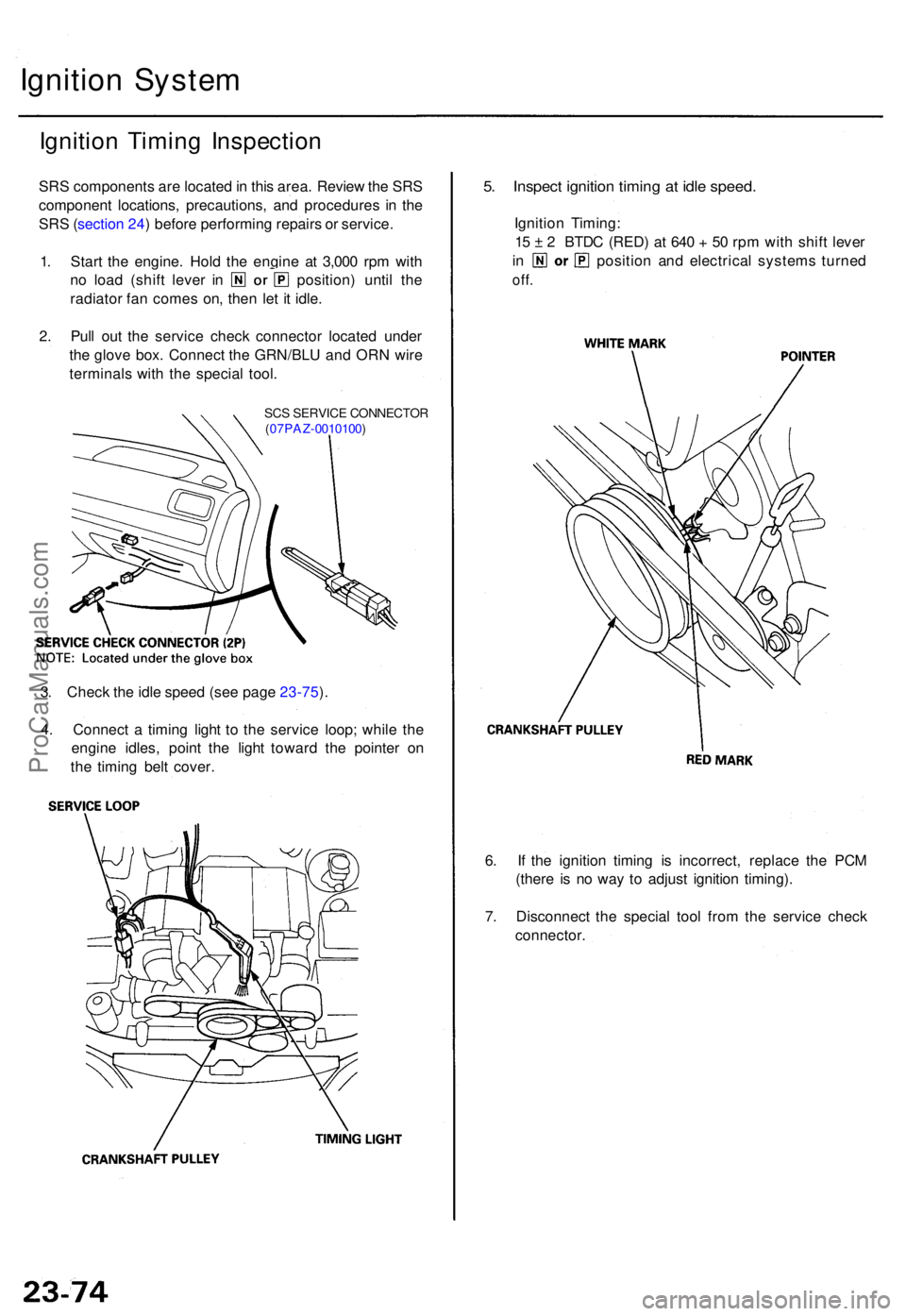
Ignition Syste m
Ignition Timin g Inspectio n
SRS component s ar e locate d in thi s area . Revie w th e SR S
componen t locations , precautions , an d procedure s i n th e
SR S (sectio n 24 ) befor e performin g repair s o r service .
1 . Star t th e engine . Hol d th e engin e a t 3,00 0 rp m wit h
no loa d (shif t leve r i n position ) unti l th e
radiato r fa n come s on , the n le t i t idle .
2 . Pul l ou t th e servic e chec k connecto r locate d unde r
th e glov e box . Connec t th e GRN/BL U an d OR N wir e
terminal s wit h th e specia l tool .
SCS SERVIC E CONNECTO R
( 07PAZ -0010100 )
5. Inspec t ignitio n timin g a t idl e speed .
Ignition Timing :
1 5 ± 2 BTD C (RED ) a t 64 0 + 50 rp m wit h shif t leve r
in positio n an d electrica l system s turne d
off.
6. I f th e ignitio n timin g i s incorrect , replac e th e PC M
(ther e i s n o wa y t o adjus t ignitio n timing) .
7 . Disconnec t th e specia l too l fro m th e servic e chec k
connector .
3
. Chec k th e idl e spee d (se e pag e 23-75 ).
4 . Connec t a timin g ligh t t o th e servic e loop ; whil e th e
engin e idles , poin t th e ligh t towar d th e pointe r o n
th e timin g bel t cover .
ProCarManuals.com
Page 619 of 1771
Horns
Componen t Locatio n Inde x
SRS component s ar e locate d i n thi s area . Revie w th e SR S componen t locations , precautions , an d procedure s i n th e SR S
( sectio n 24 ) befor e performin g repair s o r service .
HIGH HOR N
HORN RELA Y
CABLE REE LReplacement , sectio n 2 4
HOR
N SWITCHE S
UNDER-DAS H RELA Y BO XLOW HOR N
Test, page 23-201
Test
, page 23-20 3
Test
, page 23-203
Test, page 23-62
ProCarManuals.com
Page 627 of 1771
Power Seat s
Motor Tes t
CAUTION : B e carefu l no t t o damag e th e seat , interio r
tri m o r body .
1 . Remov e th e driver' s sea t (se e sectio n 20 ).
2 . Disconnec t th e 2 P connector s fro m th e powe r sea t
motors .
3 . Tes t th e motors :
NOTE : Refe r t o page 23-253 in the '9 5-9 8 Acur a
2.5TL Service Manual , P/ N 61SW504 , fo r th e item s
not shown in thi s sub-section .
CAUTION: Whe n a moto r stop s running , disconnec t bat -
ter y powe r immediately .
4. I f th e moto r doe s no t ru n o r fail s t o ru n smoothly ,
replac e it (se e sectio n 20 ).
CAUTION
: Whe n a moto r stop s running , disconnec t bat -
ter y powe r immediately .
TERMINAL SID E O F MAL E TERMINAL S
Front passenger' s seat :
Driver' s sea t (Wit h sea t heater) :
ProCarManuals.com
Page 631 of 1771
Wiper/Washer
Component Locatio n Inde x
SRS component s ar e locate d in thi s area . Revie w th e SR S componen t locations , precautions , an d procedure s i n th e SR S
sectio n (24 ) befor e performin g repair s o r service .
WINDSHIEL DWIPER/WASHE RSWITCH
Replacement , pag e 23-13 6
WINDSHIEL D WIPE R
ARMS/BLADE S
INTERMITTENT WIPE RRELAY
INTEGRATE D CONTRO L UNI T(Has built-i n intermitten t wipe r circuit )
WINDSHIEL D
WASHE R MOTO R
Replacement , sectio n 2 0 WINDSHIEL
D WIPE R MOTO R
WINDSHIEL
D WIPE R RELA Y
Test , pag e 23-5 8 Test
, pag e 23- 258
Replacement ,
sectio n 2 0
Test , pag e 23- 63
Input Test, pag e 23- 150Replacement
, section 20
Test
, pag e 23-2 60
ProCarManuals.com
Page 642 of 1771

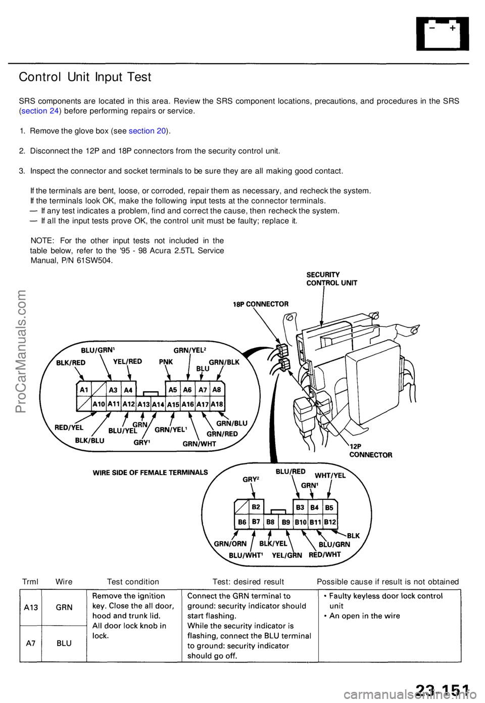
Control Uni t Inpu t Tes t
SRS component s ar e locate d i n thi s area . Revie w th e SR S componen t locations , precautions , an d procedure s i n th e SR S
( sectio n 24 ) befor e performin g repair s o r service .
1 . Remov e th e glov e bo x (se e sectio n 20 ).
2 . Disconnec t th e 12 P an d 18 P connector s fro m th e securit y contro l unit .
3 . Inspec t th e connecto r an d socke t terminal s t o b e sur e the y ar e al l makin g goo d contact .
I f th e terminal s ar e bent , loose , o r corroded , repai r the m a s necessary , an d rechec k th e system .
I f th e terminal s loo k OK , mak e th e followin g inpu t test s a t th e connecto r terminals .
I f an y tes t indicate s a problem , fin d an d correc t th e cause , the n rechec k th e system .
I f al l th e inpu t test s prov e OK , th e contro l uni t mus t b e faulty ; replac e it .
NOTE : Fo r th e othe r inpu t test s no t include d i n th e
tabl e below , refe r t o th e '9 5 - 9 8 Acur a 2.5T L Servic e
Manual , P/ N 61SW504 .
Trm l Wir e Tes t conditio n Test : desire d resul t Possibl e caus e i f resul t i s no t obtaine d
ProCarManuals.com
Page 645 of 1771

Precautions/Procedures
General Precaution s
Carefully inspec t an y SR S par t befor e yo u instal l it . D o
no t instal l an y par t tha t show s sign s o f bein g droppe d
o r improperl y handled , suc h a s dents , crack s o r defor -
mation :
— Airba g assemblie s
— Cabl e ree l
— SR S uni t
Use onl y a digita l multimete r t o chec k th e system . I f
it' s no t a Hond a multimeter , mak e sur e it s outpu t i s
1 0 m A (0.0 1 A ) o r les s whe n switche d t o th e smalles t
valu e i n th e ohmmete r range . A teste r wit h a highe r
outpu t coul d damag e th e airba g circui t o r caus e acci -
denta l deploymen t an d possibl e injury .
Do no t instal l use d SR S part s fro m anothe r vehicle .
When makin g SR S repairs , us e onl y ne w parts .
Excep t whe n performin g electrica l inspections ,
alway s disconnec t bot h th e negativ e cabl e an d posi -
tiv e cabl e fro m th e battery , an d wai t a t leas t thre e
minute s befor e beginnin g work .
Replacemen t o f th e combinatio n ligh t an d wiper /
washe r switche s an d cruis e contro l switc h ca n b e
don e withou t removin g th e steerin g wheel :
— Fo r combinatio n ligh t an d wiper/washe r switc h
replacement , se e sectio n 23 .
— Fo r cruis e contro l set/resum e switc h replacement ,
se e sectio n 23 .
Wheneve r th e ignitio n switc h i s O N (II) , o r ha s bee n
turne d OF F fo r les s tha n thre e minutes , b e carefu l no t
to bum p th e SR S unit ; th e airbag s coul d accidentall y
deploy an d caus e damag e o r injury .
Wheneve r th e airba g ha s bee n activated , replac e th e
SR S unit .
The origina l radi o ha s a code d thef t protectio n circuit .
B e sur e t o ge t th e customer' s cod e numbe r befor e dis -
connectin g th e batter y cables .
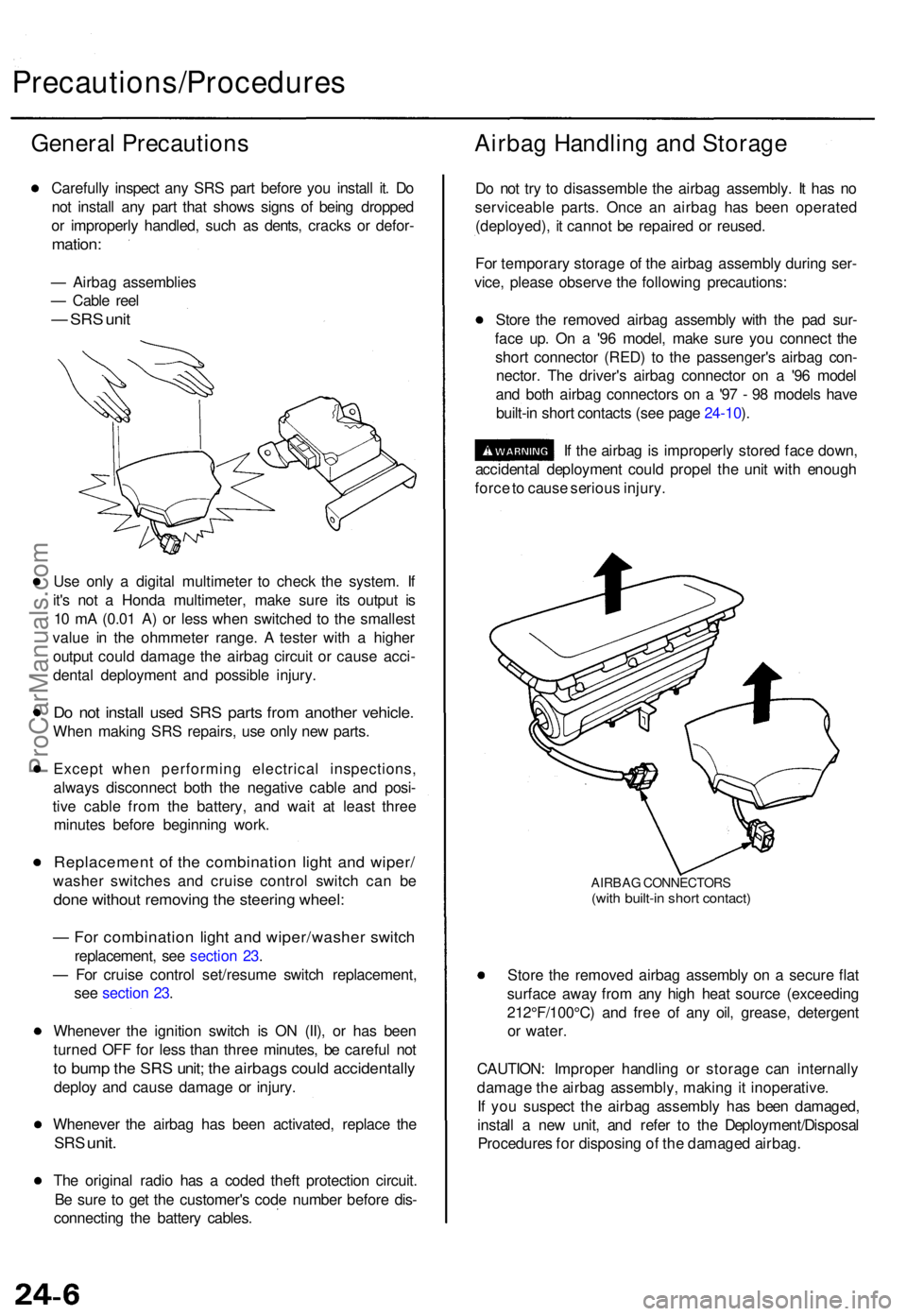
Airbag Handlin g an d Storag e
Do no t tr y t o disassembl e th e airba g assembly . I t ha s n o
serviceabl e parts . Onc e a n airba g ha s bee n operate d
(deployed) , i t canno t b e repaire d o r reused .
Fo r temporar y storag e o f th e airba g assembl y durin g ser -
vice , pleas e observ e th e followin g precautions :
Stor e th e remove d airba g assembl y wit h th e pa d sur -
fac e up . O n a '9 6 model , mak e sur e yo u connec t th e
shor t connecto r (RED ) t o th e passenger' s airba g con -
nector . Th e driver' s airba g connecto r o n a '9 6 mode l
an d bot h airba g connector s o n a '9 7 - 9 8 model s hav e
built-i n shor t contact s (se e pag e 24-10 ).
I f th e airba g is improperl y store d fac e down ,
accidenta l deploymen t coul d prope l th e uni t wit h enoug h
forc e to caus e seriou s injury .
AIRBA G CONNECTOR S(with built-i n shor t contact )
Store th e remove d airba g assembl y o n a secur e fla t
surfac e awa y fro m an y hig h hea t sourc e (exceedin g
212°F/100°C ) an d fre e o f an y oil , grease , detergen t
o r water .
CAUTION : Imprope r handlin g o r storag e ca n internall y
damag e th e airba g assembly , makin g it inoperative .
I f yo u suspec t th e airba g assembl y ha s bee n damaged ,
instal l a ne w unit , an d refe r t o th e Deployment/Disposa l
Procedure s fo r disposin g o f th e damage d airbag .
ProCarManuals.com