1995 ACURA TL service
[x] Cancel search: servicePage 332 of 1771
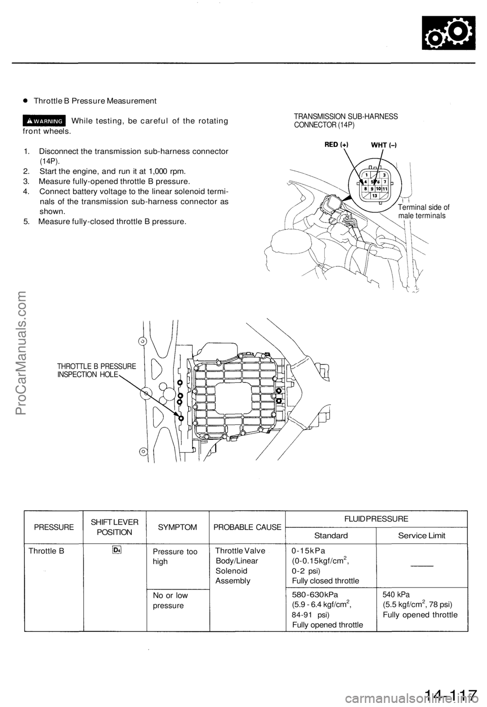
Throttle B Pressure Measurement
While testing, be careful of the rotating
front wheels.
1. Disconnect the transmission sub-harness connector
(14P).
2. Start the engine, and run it at 1,000 rpm.
3. Measure fully-opened throttle B pressure.
4. Connect battery voltage to the linear solenoid termi-
nals of the transmission sub-harness connector as
shown.
5. Measure fully-closed throttle B pressure.
TRANSMISSION SUB-HARNESS
CONNECTOR (14P)
Terminal side of
male terminals
THROTTLE B PRESSURE
INSPECTION HOLE
PRESSURE
Throttle B
SHIFT LEVER
POSITION
SYMPTOM
Pressure too
high
No or low
pressure
PROBABLE CAUSE
Throttle Valve
Body/Linear
Solenoid
Assembly
FLUID PRESSURE
Standard
0-15kPa
(0-0.15kgf/cm2,
0-2
psi)
Fully closed throttle
580
-
630
kPa
(5.9 - 6.4 kgf/cm2,
84-91 psi)
Fully opened throttle
Service Limit
540 kPa
(5.5 kgf/cm2, 78 psi)
Fully opened throttle
14-117ProCarManuals.com
Page 334 of 1771
![ACURA TL 1995 Service Repair Manual
6. Disconnect the transmission sub-harness connector (14P).
7. Start the engine, and run it at 2,000 rpm.
TRANSMISSION SUB-HARNESS
CONNECTOR (14P)
8. Shift to the [HI or [P] position, and measure ACURA TL 1995 Service Repair Manual
6. Disconnect the transmission sub-harness connector (14P).
7. Start the engine, and run it at 2,000 rpm.
TRANSMISSION SUB-HARNESS
CONNECTOR (14P)
8. Shift to the [HI or [P] position, and measure](/manual-img/32/56993/w960_56993-333.png)
6. Disconnect the transmission sub-harness connector (14P).
7. Start the engine, and run it at 2,000 rpm.
TRANSMISSION SUB-HARNESS
CONNECTOR (14P)
8. Shift to the [HI or [P] position, and measure line pressure at fully-opened throttle.
9. Connect battery voltage to the linear solenoid terminals of the transmission sub-harness connector as shown.
10. Measure line pressure at fully-closed throttle.
If line pressure is out of specification, check and repair the probable cause in the table below.
PRESSURE
Line
SHIFT LEVER
POSITION
or
SYMPTOM
No (or
low)
line pressure
PROBABLE CAUSE
Torque converter,
ATF pump, pres-
sure regulator.
torque converter
check valve
FLUID PRESSURE
Standard
520 kPa
(5.3 kgf/cm2, 75 psi)
Fully closed throttle
|
910 kPa
(9.3 kgf/cm2, 130 psi)
Fully opened throttle
Service Limit
500 kPa
(5.1 kgf/cm2, 73 psi)
Fully closed throttle
790 kPa
(8.1 kgf/cm2, 120 psi)
Fully opened throttle
11. Stop the engine, and connect the transmission sub-harness connector (14P).
12. Disconnect the special tool from line pressure inspection hole, and connect the special tool to each inspection hole.
13. Start the engine, and run it at 2,000 rpm.
(cont'd)ProCarManuals.com
Page 335 of 1771
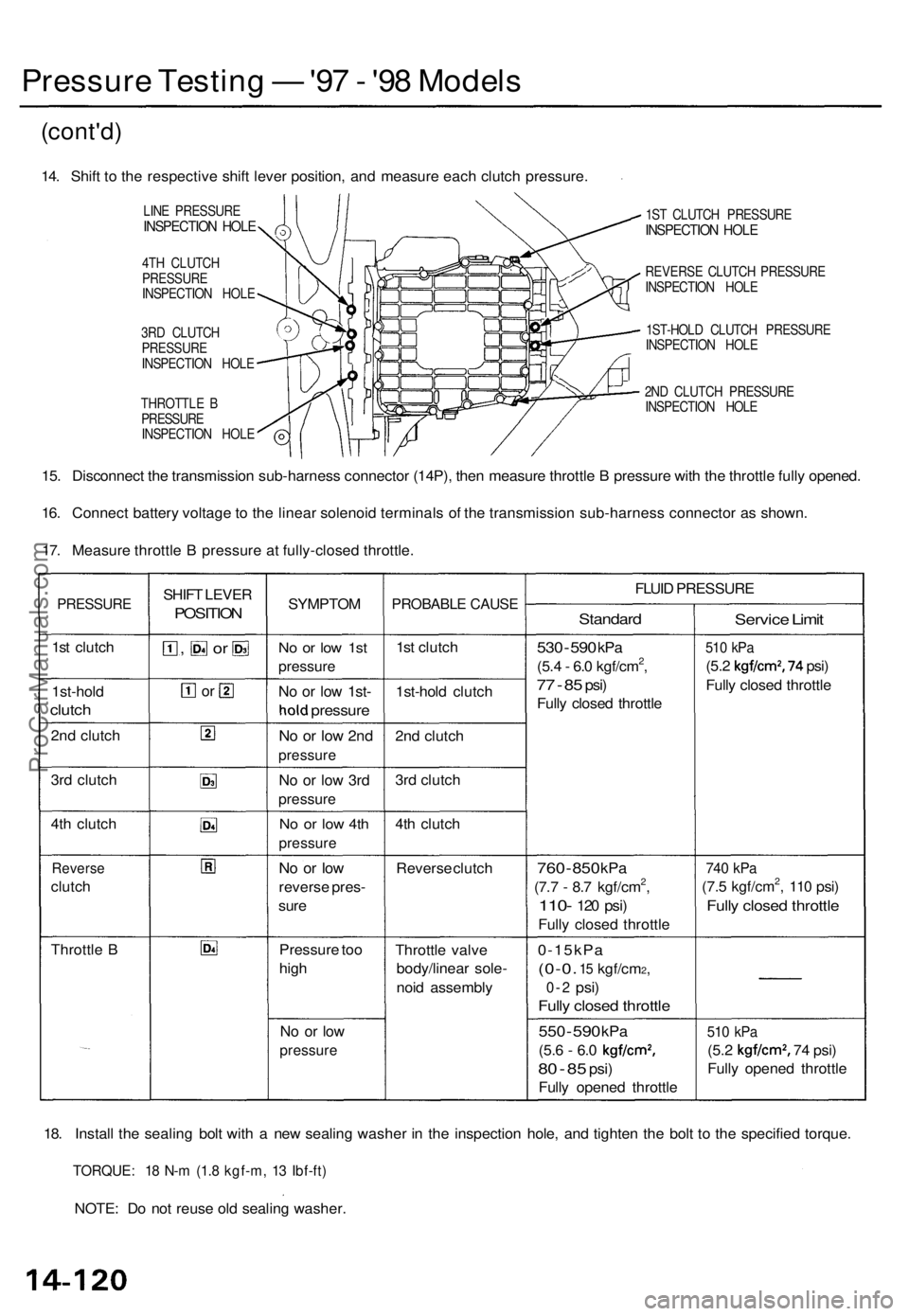
Pressure Testin g — '97 - '9 8 Model s
(cont'd )
14. Shif t t o th e respectiv e shif t leve r position , an d measur e eac h clutc h pressure .
LINE PRESSUR EINSPECTION HOL E
4TH CLUTC H
PRESSUR E
INSPECTIO N HOL E
3R D CLUTC H
PRESSUR E
INSPECTIO N HOL E
THROTTL E B
PRESSUR E
INSPECTIO N HOL E 1S
T CLUTC H PRESSUR E
INSPECTION HOL E
REVERS E CLUTC H PRESSUR E
INSPECTIO N HOL E
1ST-HOL D CLUTC H PRESSUR E
INSPECTIO N HOL E
2N D CLUTC H PRESSUR E
INSPECTIO N HOL E
15. Disconnec t th e transmissio n sub-harnes s connecto r (14P) , the n measur e throttl e B pressur e wit h th e throttl e full y opened .
16 . Connec t batter y voltag e to th e linea r solenoi d terminal s o f th e transmissio n sub-harnes s connecto r a s shown .
17 . Measur e throttl e B pressur e a t fully-close d throttle .
PRESSUR E
1st clutc h
1st-hol d
clutch
2nd clutc h
3r d clutc h
4t h clutc h
Revers e
clutch
Throttl e B SHIF
T LEVE R
POSITIO N
, o r
or
SYMPTO M
No o r lo w 1s t
pressur e
No o r lo w 1st -
hold pressur e
No o r lo w 2n d
pressur e
No o r lo w 3r d
pressur e
No o r lo w 4t h
pressur e
No o r lo w
revers e pres -
sur e
Pressur e to o
hig h
No o r lo w
pressur e
PROBABL E CAUS E
1st clutc h
1st-hol d clutc h
2n d clutc h
3r d clutc h
4t h clutc h
Revers e clutc h
Throttl e valv e
body/linea r sole -
noi d assembl y FLUI
D PRESSUR E
Standard
530 - 59 0 kP a
(5.4 - 6. 0 kgf/cm2,
77 - 8 5 psi )
Full y close d throttl e
760 - 85 0 kP a
(7.7 - 8. 7 kgf/cm2,
110 - 120 psi )
Full y close d throttl e
0-15kP a
(0-0. 15 kgf/cm2,
0-2 psi )
Fully close d throttl e
550 - 59 0 kP a
(5.6 - 6. 0 kgf/cm2,
80 - 8 5 psi )
Full y opene d throttl e
Service Limi t
510 kP a
(5.2 kgf/cm2, 74 psi )
Full y close d throttl e
740 kP a
(7.5 kgf/cm2, 11 0 psi )
Full y close d throttl e
510 kP a
(5.2 kgf/cm2, 74 psi )
Full y opene d throttl e
18 . Instal l th e sealin g bol t wit h a ne w sealin g washe r i n th e inspectio n hole , an d tighte n th e bol t t o th e specifie d torque .
TORQUE : 1 8 N- m (1. 8 kgf-m , 1 3 Ibf-ft )
NOTE : D o no t reus e ol d sealin g washer .
ProCarManuals.com
Page 403 of 1771
Clutch
Reassembl y (cont'd )
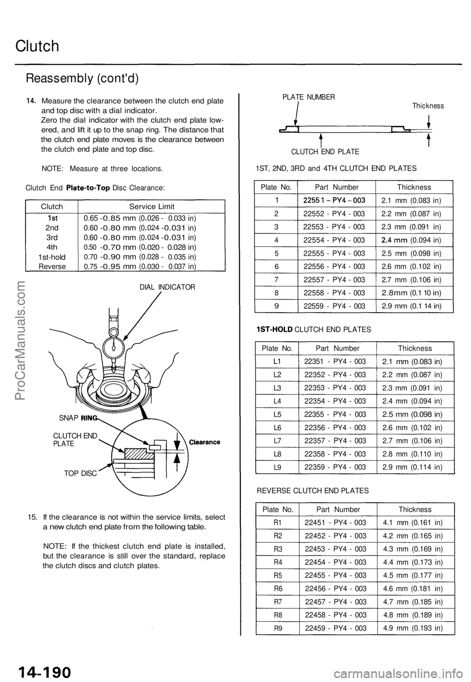
14. Measur e th e clearanc e betwee n th e clutc h en d plat e
and to p dis c wit h a dia l indicator .
Zero th e dia l indicato r wit h th e clutc h en d plat e low -
ered , an d lif t i t u p to th e sna p ring . Th e distanc e tha t
the clutc h en d plat e move s is th e clearanc e betwee n
the clutc h en d plat e an d to p disc .
NOTE : Measur e a t thre e locations .
Clutch En d Plate-to-To p Disc Clearance :
Clutch
1st
2n d
3rd
4th
1st-hol d
Revers e
Service Limi t
0.65
0.6 0
0.6 0
0.50
0.7 0
0.7 5
-0.8 5
-0.80
-0.8 0
-0.70
-0.9 0
-0.9 5
mm
m m
m m
mm
m m
m m
(0
( 0
( 0
(0
02 6
02 4
02 4
020
(0.02 8
(003 0
- 0.03 3
-0.031
-0.03 1
- 0.02 8
- 0.03 5
- 0.03 7
in)
in)
in)
in)
in )
in )
DIA L INDICATO R
TOP DIS C
15. I f th e clearanc e is no t withi n th e servic e limits , selec t
a ne w clutc h en d plat e fro m th e followin g table .
NOTE : I f th e thickes t clutc h en d plat e i s installed ,
but th e clearanc e i s stil l ove r th e standard , replac e
the clutc h disc s an d clutc h plates .
PLATE NUMBE RThicknes s
CLUTCH EN D PLAT E
1ST, 2ND , 3R D an d 4T H CLUTC H EN D PLATE S
Plat e No .
1
2
3
4
5
6
7
8
9
Part Numbe r
2255 1-PY4 - 003
2255 2 - PY 4 - 00 3
2255 3 - PY 4 - 00 3
2255 4 - PY 4 - 00 3
2255 5 - PY 4 - 00 3
2255 6 - PY 4 - 00 3
2255 7 - PY 4 - 00 3
2255 8 - PY 4 - 00 3
2255 9 - PY 4 - 00 3 Thicknes
s
2. 1 m m (0.08 3 in )
2. 2 m m (0.08 7 in )
2. 3 m m (0.09 1 in )
2.4m m (0.09 4 in )
2. 5 m m (0.09 8 in )
2. 6 m m (0.10 2 in )
2. 7 m m (0.10 6 in )
2.8m m (0.1 10 in )
2.9 m m (0. 1 14 in )
1ST-HOL D CLUTCH EN D PLATE S
Plat e No .
L1
L 2
L3
L 4
L5
L 6
L7
L 8
L 9
Par t Numbe r
2235 1 - PY 4 - 00 3
2235 2 - PY 4 - 00 3
2235 3 - PY 4 - 00 3
2235 4 - PY 4 - 00 3
2235 5 - PY 4 - 00 3
2235 6 - PY 4 - 00 3
2235 7 - PY 4 - 00 3
2235 8 - PY 4 - 00 3
2235 9 - PY 4 - 00 3 Thicknes
s
2.1 m m (0.08 3 in )
2.2 m m (0.08 7 in )
2. 3 m m (0.09 1 in )
2. 4 m m (0.09 4 in )
2.5 m m (0.09 8 in )
2.6 m m (0.10 2 in )
2. 7 m m (0.10 6 in )
2. 8 m m (0.11 0 in )
2. 9 m m (0.11 4 in )
REVERS E CLUTC H EN D PLATE S
Plat e No .
R1
R 2
R3
R 4
R5
R6
R7
R 8
R9
Par t Numbe r
2245 1 - PY 4 - 00 3
2245 2 - PY 4 - 00 3
2245 3 - PY 4 - 00 3
2245 4 - PY 4 - 00 3
2245 5 - PY 4 - 00 3
2245 6 - PY 4 - 00 3
2245 7 - PY 4 - 00 3
2245 8 - PY 4 - 00 3
2245 9 - PY 4 - 00 3 Thicknes
s
4. 1 m m (0.16 1 in )
4. 2 m m (0.16 5 in )
4. 3 m m (0.16 9 in )
4. 4 m m (0.17 3 in )
4. 5 m m (0.17 7 in )
4. 6 m m (0.18 1 in )
4. 7 m m (0.18 5 in )
4. 8 m m (0.18 9 in )
4. 9 m m (0.19 3 in )
SNA P RING
CLUTC H EN DPLAT EClearanc e
ProCarManuals.com
Page 424 of 1771
Transmission
Installation
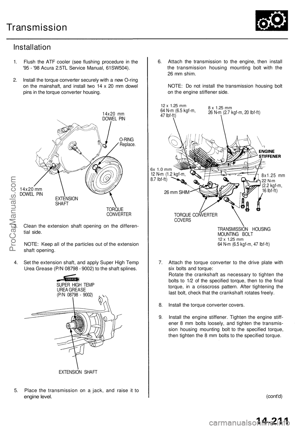
1. Flush the ATF cooler (see flushing procedure in the
'95 - '98 Acura 2.5TL Service Manual, 61SW504).
2. Install the torque converter securely with a new O-ring
on the mainshaft, and install two 14 x 20 mm dowel
pins in the torque converter housing.
14x20 mm
DOWEL PIN
14x20 mm
DOWEL PIN
O-RING
Replace.
EXTENSION
SHAFT
TORQUE
CONVERTER
3. Clean the extension shaft opening on the differen-
tial side.
NOTE: Keep all of the particles out of the extension
shaft opening.
4. Set the extension shaft, and apply Super High Temp
Urea Grease (P/N 08798 - 9002) to the shaft splines.
SUPER HIGH TEMP
UREA GREASE
(P/N 08798 - 9002)
EXTENSION SHAFT
5. Place the transmission on a jack, and raise it to
engine level.
6. Attach the transmission to the engine, then install
the transmission housing mounting bolt with the
26 mm shim.
NOTE: Do not install the transmission housing bolt
on the engine stiffener side.
12 x
1.25
mm
64 N-m (6.5 kgf-m,
47 Ibf-ft)
8 x
1.25
mm
26 N-m (2.7 kgf-m, 20 Ibf-ft)
6x 1.0 mm
12 N-m (1.2 kgf-m,
8.7 Ibf-ft)
26 mm SHIM
8x1.25 mm
22 N-m
(2.2 kgf-m,
16 Ibf-ft)
TORQUE CONVERTER
COVERS
TRANSMISSION HOUSING
MOUNTING BOLT
12 x
1.25
mm
64 N-m (6.5 kgf-m, 47 Ibf-ft)
7. Attach the torque converter to the drive plate with
six bolts and torque:
Rotate the crankshaft as necessary to tighten the
bolts to 1/2 of the specified torque, then to the final
torque, in a crisscross pattern. After tightening the
last bolt, check that the crankshaft rotates freely.
8. Install the torque converter covers.
9. Install the engine stiffener. Tighten the engine stiff-
ener 8 mm bolts loosely, and tighten the transmis-
sion housing mounting bolt to the specified torque,
then tighten the 8 mm bolts to the specified torque.
(cont'd)ProCarManuals.com
Page 468 of 1771
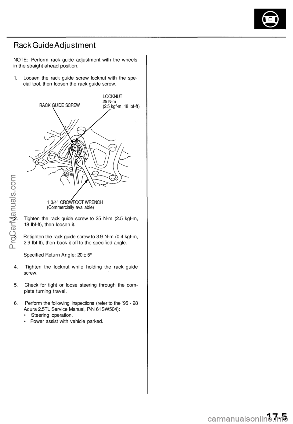
Rack Guide Adjustment
NOTE: Perform rack guide adjustment with the wheels
in the straight ahead position.
1. Loosen the rack guide screw locknut with the spe-
cial tool, then loosen the rack guide screw.
RACK GUIDE SCREW
LOCKNUT
25 N-m
(2.5 kgf-m, 18 Ibf-ft)
1 3/4" CROWFOOT WRENCH
(Commercially available)
2. Tighten the rack guide screw to 25 N-m (2.5 kgf-m,
18 Ibf-ft), then loosen it.
3. Retighten the rack guide screw to 3.9 N-m (0.4 kgf-m,
2.9 Ibf-ft), then back it off to the specified angle.
Specified Return Angle: 20 ± 5°
4. Tighten the locknut while holding the rack guide
screw.
5. Check for tight or loose steering through the com-
plete turning travel.
6. Perform the following inspections (refer to the '95 - 98
Acura 2.5TL Service Manual, P/N 61SW504):
• Steering operation.
• Power assist with vehicle parked.ProCarManuals.com
Page 471 of 1771
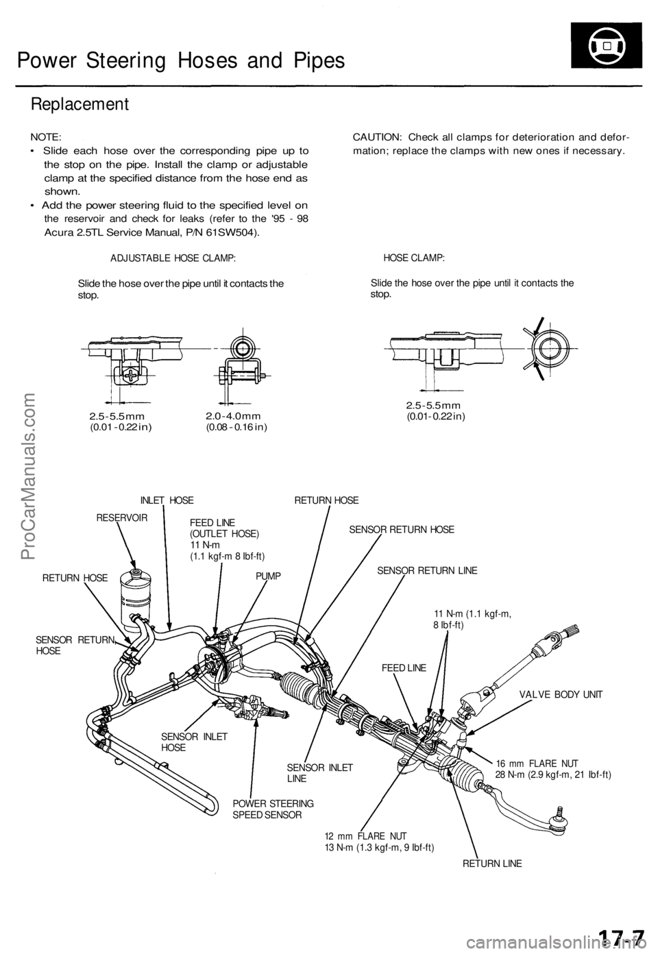
Power Steering Hoses and Pipes
Replacement
NOTE:
• Slide each hose over the corresponding pipe up to
the stop on the pipe. Install the clamp or adjustable
clamp at the specified distance from the hose end as
shown.
• Add the power steering fluid to the specified level on
the reservoir and check for leaks (refer to the '95 - 98
Acura 2.5TL Service Manual, P/N 61SW504).
CAUTION: Check all clamps for deterioration and defor-
mation; replace the clamps with new ones if necessary.
ADJUSTABLE HOSE CLAMP:
HOSE CLAMP:
Slide the hose over the pipe until it contacts the
stop.
Slide the hose over the pipe until it contacts the
stop.
2.5
-
5.5
mm
(0.01
-
0.22
in)
2.0
-
4.0
mm
(0.08
-
0.16
in)
2.5
-
5.5
mm
(0.01- 0.22 in)
INLET HOSE
RETURN HOSE
RESERVOIR
SENSOR RETURN HOSE
RETURN HOSE
SENSOR RETURN
HOSE
VALVE BODY UNIT
16 mm FLARE NUT
28 N-m (2.9 kgf-m, 21 Ibf-ft)
12 mm FLARE NUT
13 N-m (1.3 kgf-m, 9 Ibf-ft)
RETURN LINE
FEED LINE
(OUTLET HOSE)
11 N-m
(1.1 kgf-m 8 Ibf-ft)
PUMP
SENSOR INLET
HOSE
SENSOR INLET
LINE
POWER STEERING
SPEED SENSOR
FEED LINE
11 N-m (1.1 kgf-m,
8 Ibf-ft)
SENSOR RETURN LINEProCarManuals.com
Page 486 of 1771
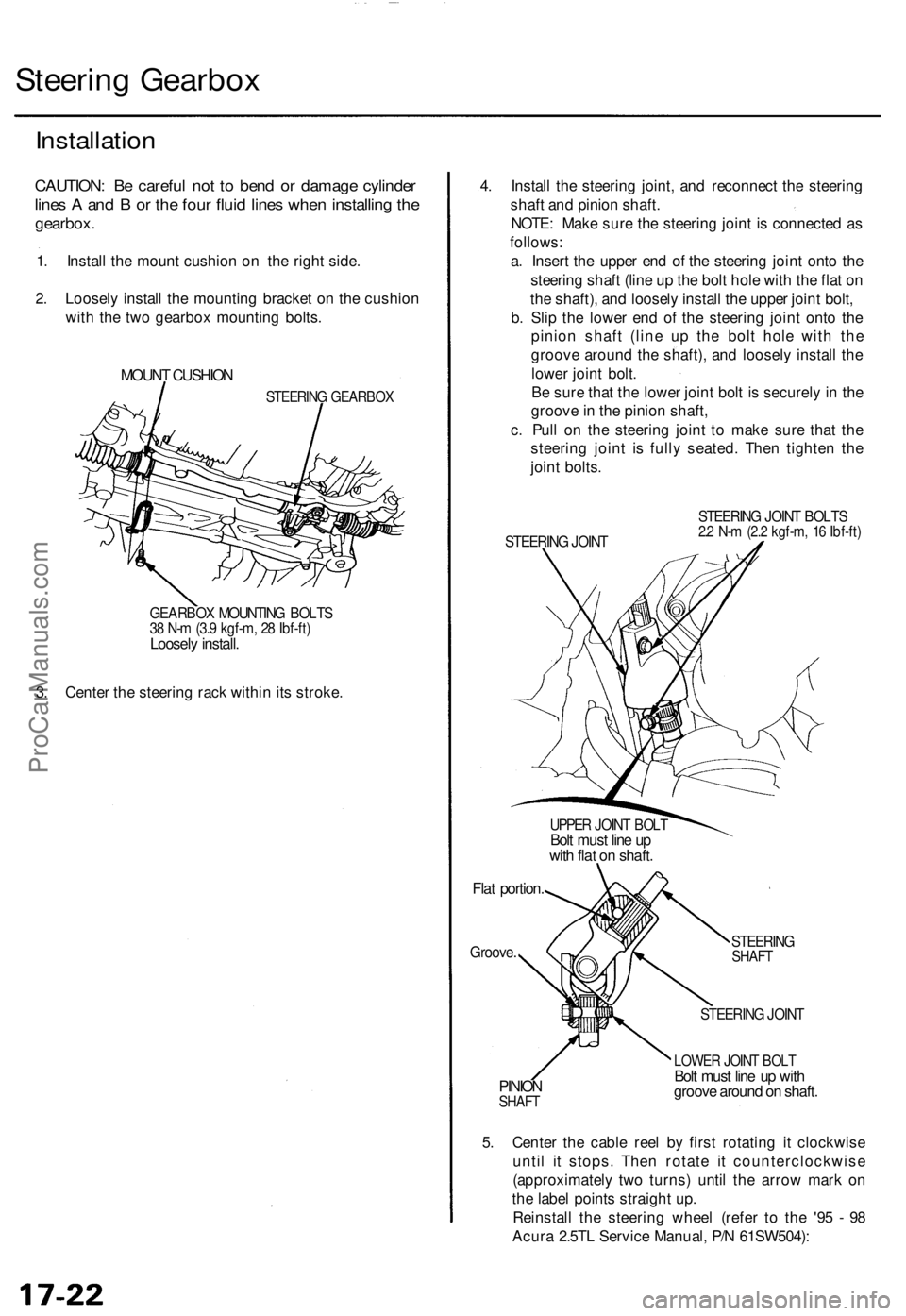
Steering Gearbox
Installation
CAUTION: Be careful not to bend or damage cylinder
lines A and B or the four fluid lines when installing the
gearbox.
1. Install the mount cushion on the right side.
2. Loosely install the mounting bracket on the cushion
with the two gearbox mounting bolts.
MOUNT CUSHION
STEERING GEARBOX
GEARBOX MOUNTING BOLTS
38 N-m (3.9 kgf-m, 28 Ibf-ft)
Loosely install.
3. Center the steering rack within its stroke.
4. Install the steering joint, and reconnect the steering
shaft and pinion shaft.
NOTE: Make sure the steering joint is connected as
follows:
a. Insert the upper end of the steering joint onto the
steering shaft (line up the bolt hole with the flat on
the shaft), and loosely install the upper joint bolt,
b. Slip the lower end of the steering joint onto the
pinion shaft (line up the bolt hole with the
groove around the shaft), and loosely install the
lower joint bolt.
Be sure that the lower joint bolt is securely in the
groove in the pinion shaft,
c. Pull on the steering joint to make sure that the
steering joint is fully seated. Then tighten the
joint bolts.
STEERING JOINT
STEERING JOINT BOLTS
2.2 N-m (2.2 kgf-m, 16 Ibf-ft)
UPPER JOINT BOLT
Bolt must line up
with flat on shaft.
Flat portion.
Groove.
STEERING
SHAFT
PINION
SHAFT
STEERING JOINT
LOWER JOINT BOLT
Bolt must line up with
groove around on shaft.
5. Center the cable reel by first rotating it clockwise
until it stops. Then rotate it counterclockwise
(approximately two turns) until the arrow mark on
the label points straight up.
Reinstall the steering wheel (refer to the '95 - 98
Acura 2.5TL Service Manual, P/N 61SW504):ProCarManuals.com