1995 ACURA TL service
[x] Cancel search: servicePage 83 of 1771
Camshaft
Inspection (cont'd)
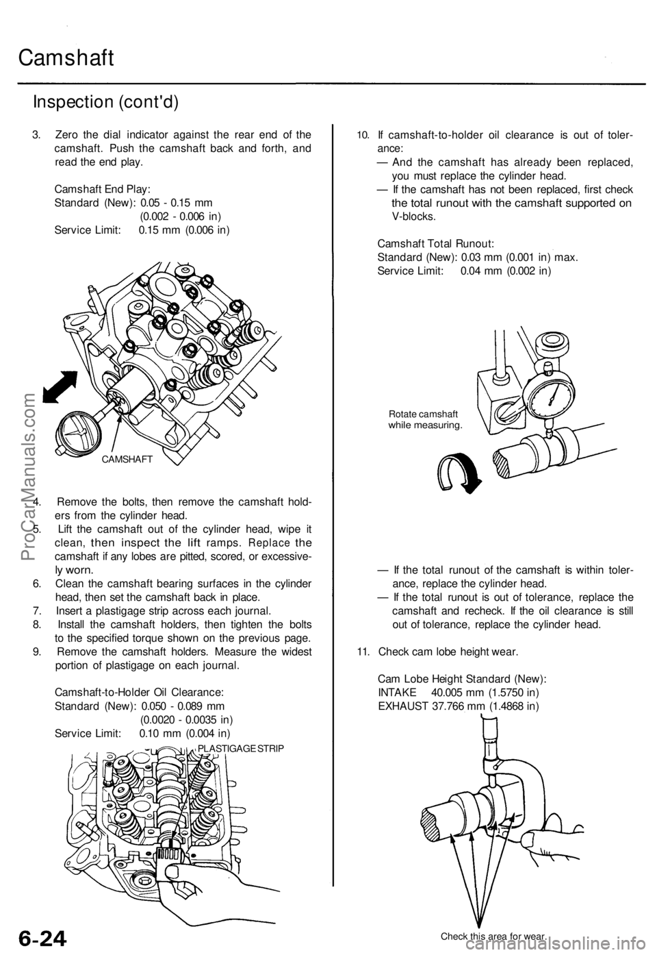
3. Zero the dial indicator against the rear end of the
camshaft. Push the camshaft back and forth, and
read the end play.
Camshaft End Play:
Standard (New): 0.05 - 0.15 mm
(0.002 - 0.006 in)
Service Limit: 0.15 mm (0.006 in)
4. Remove the bolts, then remove the camshaft hold-
ers from the cylinder head.
5. Lift the camshaft out of the cylinder head, wipe it
clean,
then
inspect
the
lift
ramps.
Replace
the
camshaft if any lobes are pitted, scored, or excessive-
ly worn.
6. Clean the camshaft bearing surfaces in the cylinder
head, then set the camshaft back in place.
7. Insert a plastigage strip across each journal.
8. Install the camshaft holders, then tighten the bolts
to the specified torque shown on the previous page.
9. Remove the camshaft holders. Measure the widest
portion of plastigage on each journal.
Camshaft-to-Holder Oil Clearance:
Standard (New): 0.050 - 0.089 mm
(0.0020 - 0.0035 in)
Service Limit: 0.10 mm (0.004 in)
PLASTIGAGE STRIP
10.
If camshaft-to-holder oil clearance is out of toler-
ance:
— And the camshaft has already been replaced,
you must replace the cylinder head.
— If the camshaft has not been replaced, first check
the total runout with the camshaft supported on
V-blocks.
Camshaft Total Runout:
Standard (New): 0.03 mm (0.001 in) max.
Service Limit: 0.04 mm (0.002 in)
Rotate camshaft
while measuring.
— If the total runout of the camshaft is within toler-
ance, replace the cylinder head.
— If the total runout is out of tolerance, replace the
camshaft and recheck. If the oil clearance is still
out of tolerance, replace the cylinder head.
11. Check cam lobe height wear.
Cam Lobe Height Standard (New):
INTAKE 40.005 mm (1.5750 in)
EXHAUST 37.766 mm (1.4868 in)
Check this area for wear.
CAMSHAFTProCarManuals.com
Page 84 of 1771
Rocker Arms and Shafts
Clearance Inspection
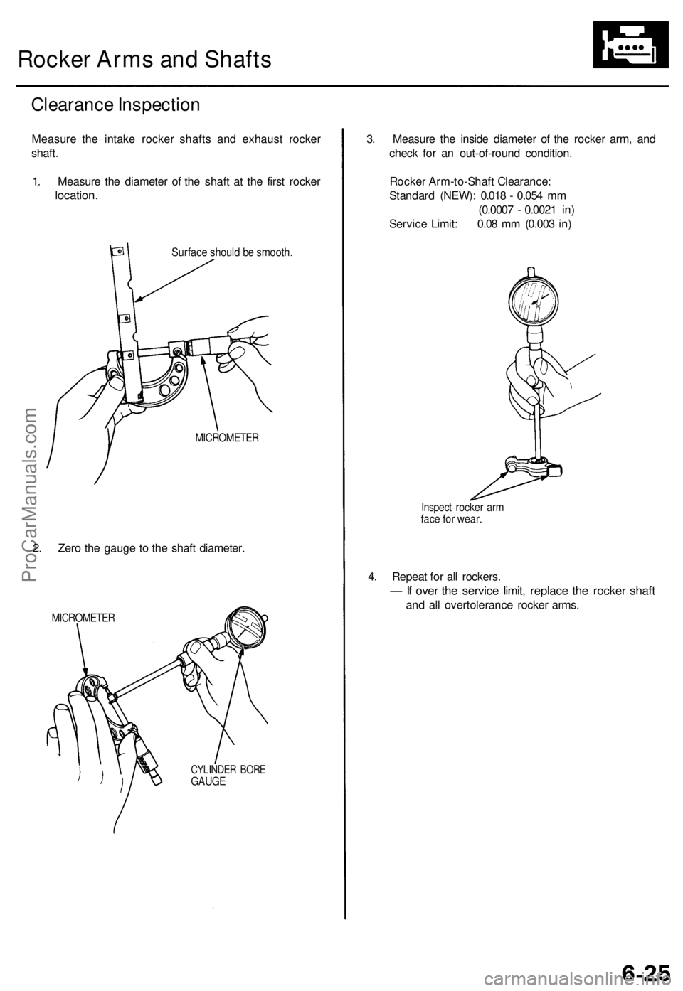
Measure the intake rocker shafts and exhaust rocker
shaft.
1. Measure the diameter of the shaft at the first rocker
location.
Surface should be smooth.
MICROMETER
2. Zero the gauge to the shaft diameter.
MICROMETER
CYLINDER BORE
GAUGE
3. Measure the inside diameter of the rocker arm, and
check for an out-of-round condition.
Rocker Arm-to-Shaft Clearance:
Standard (NEW): 0.018 - 0.054 mm
(0.0007 - 0.0021 in)
Service Limit: 0.08 mm (0.003 in)
Inspect rocker arm
face for wear.
4. Repeat for all rockers.
— If over the service limit, replace the rocker shaft
and all overtolerance rocker arms.ProCarManuals.com
Page 86 of 1771
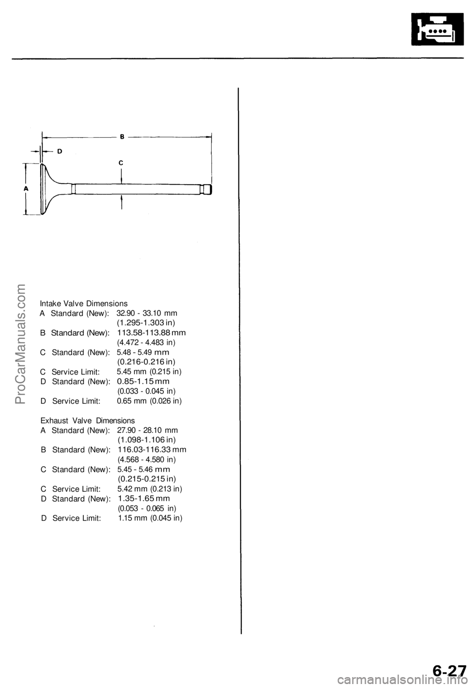
Intake Valve Dimensions
A Standard (New):
B Standard (New):
C Standard (New):
C Service Limit:
D Standard (New):
D Service Limit:
32.90 - 33.10 mm
(1.295-1.303 in)
113.58-113.88 mm
(4.472 - 4.483 in)
5.48
-
5.49
mm
(0.216-0.216 in)
5.45 mm (0.215 in)
0.85-1.15 mm
(0.033 - 0.045 in)
0.65 mm (0.026 in)
Exhaust Valve Dimensions
A Standard (New):
B Standard (New):
C Standard (New):
C Service Limit:
D Standard (New):
D Service Limit:
27.90 - 28.10 mm
(1.098-1.106 in)
116.03-116.33 mm
(4.568 - 4.580 in)
5.45
-
5.46
mm
(0.215-0.215 in)
5.42 mm (0.213 in)
1.35-1.65 mm
(0.053 - 0.065 in)
1.15 mm (0.045 in)ProCarManuals.com
Page 105 of 1771
Connecting Rod Bearings
Clearance
Selection
1. Remove the connecting rod cap and bearing half.
2. Clean the crankshaft rod journal and bearing half
with a clean shop towel.
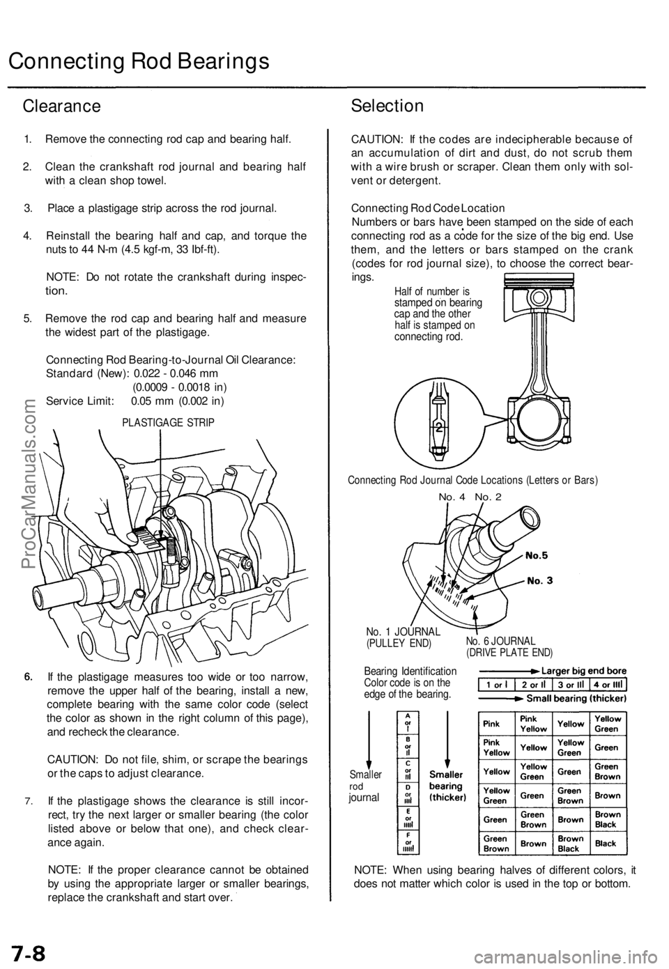
3. Place a plastigage strip across the rod journal.
4. Reinstall the bearing half and cap, and torque the
nuts to 44 N-m (4.5 kgf-m, 33 Ibf-ft).
NOTE: Do not rotate the crankshaft during inspec-
tion.
5. Remove the rod cap and bearing half and measure
the widest part of the plastigage.
Connecting Rod Bearing-to-Journal Oil Clearance:
Standard (New): 0.022 - 0.046 mm
(0.0009 - 0.0018 in)
Service Limit: 0.05 mm (0.002 in)
PLASTIGAGE STRIP
7.
If the plastigage measures too wide or too narrow,
remove the upper half of the bearing, install a new,
complete bearing with the same color code (select
the color as shown in the right column of this page),
and recheck the clearance.
CAUTION: Do not file, shim, or scrape the bearings
or the caps to adjust clearance.
If the plastigage shows the clearance is still incor-
rect, try the next larger or smaller bearing (the color
listed above or below that one), and check clear-
ance again.
NOTE: If the proper clearance cannot be obtained
by using the appropriate larger or smaller bearings,
replace the crankshaft and start over.
CAUTION: If the codes are indecipherable because of
an accumulation of dirt and dust, do not scrub them
with a wire brush or scraper. Clean them only with sol-
vent or detergent.
Connecting Rod Code Location
Numbers or bars have been stamped on the side of each
connecting rod as a code for the size of the big end. Use
them, and the letters or bars stamped on the crank
(codes for rod journal size), to choose the correct bear-
ings.
Half of number is
stamped on bearing
cap and the other
half is stamped on
connecting rod.
Connecting Rod Journal Code Locations (Letters or Bars)
No. 4 No. 2
No. 1 JOURNAL
(PULLEY END)
Bearing Identification
Color code is on the
edge of the bearing.
No. 6 JOURNAL
(DRIVE PLATE END)
Smaller
rod
journal
NOTE: When using bearing halves of different colors, it
does not matter which color is used in the top or bottom.ProCarManuals.com
Page 108 of 1771
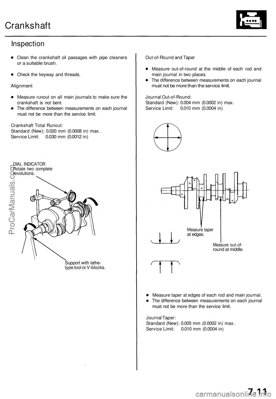
Crankshaft
Inspection
Clean the crankshaft oil passages with pipe cleaners
or a suitable brush.
Check the keyway and threads.
Alignment
Measure runout on all main journals to make sure the
crankshaft is not bent.
The difference between measurements on each journal
must not be more than the service limit.
Crankshaft Total Runout:
Standard (New): 0.020 mm (0.0008 in) max.
Service Limit: 0.030 mm (0.0012 in)
DIAL INDICATOR
Rotate two complete
revolutions.
Support with lathe-
type tool or V-blocks.
Out-of-Round and Taper
Measure out-of-round at the middle of each rod and
main journal in two places.
The difference between measurements on each journal
must not be more than the service limit.
Journal Out-of-Round:
Standard (New): 0.004 mm (0.0002 in) max.
Service Limit: 0.010 mm (0.0004 in)
Measure out-of-
round at middle.
Measure taper at edges of each rod and main journal.
The difference between measurements on each journal
must not be more than the service limit.
Journal Taper:
Standard (New): 0.005 mm (0.0002 in) max.
Service Limit: 0.010 mm (0.0004 in)
Measure taper
at edges.ProCarManuals.com
Page 128 of 1771
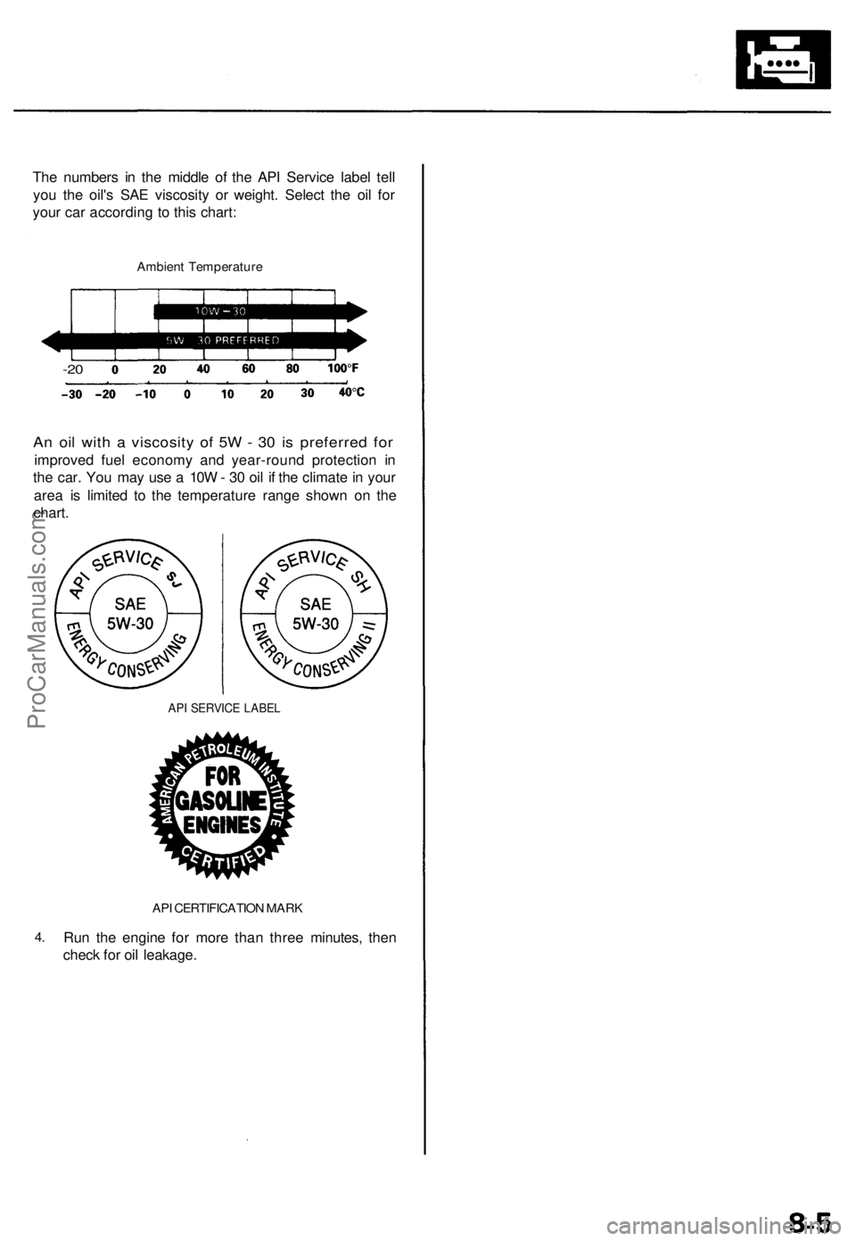
The numbers in the middle of the API Service label tell
you the oil's SAE viscosity or weight. Select the oil for
your car according to this chart:
Ambient Temperature
-20
An oil with a viscosity of 5W - 30 is preferred for
improved fuel economy and year-round protection in
the car. You may use a 10W - 30 oil if the climate in your
area is limited to the temperature range shown on the
chart.
API SERVICE LABEL
4.
API CERTIFICATION MARK
Run the engine for more than three minutes, then
check for oil leakage.ProCarManuals.com
Page 181 of 1771
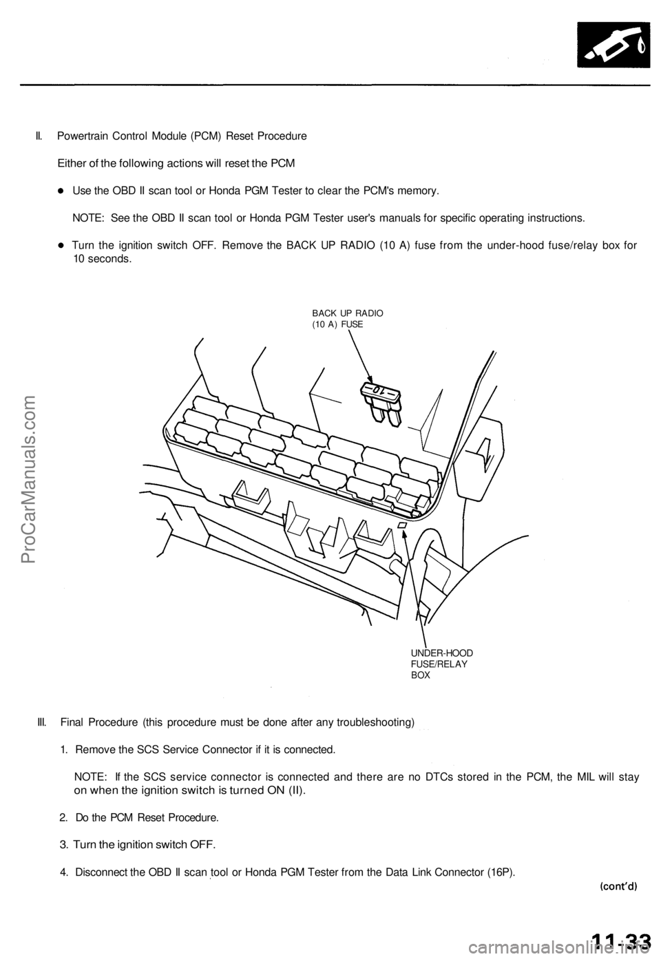
II. Powertrain Control Module (PCM) Reset Procedure
Either of the following actions will reset the PCM
Use the OBD II scan tool or Honda PGM Tester to clear the PCM's memory.
NOTE: See the OBD II scan tool or Honda PGM Tester user's manuals for specific operating instructions.
Turn the ignition switch OFF. Remove the BACK UP RADIO (10 A) fuse from the under-hood fuse/relay box for
10 seconds.
BACK UP RADIO
(10 A) FUSE
UNDER-HOOD
FUSE/RELAY
BOX
III. Final Procedure (this procedure must be done after any troubleshooting)
1. Remove the SCS Service Connector if it is connected.
NOTE: If the SCS service connector is connected and there are no DTCs stored in the PCM, the MIL will stay
on when the ignition switch is turned ON (II).
2. Do the PCM Reset Procedure.
3. Turn the ignition switch OFF.
4. Disconnect the OBD II scan tool or Honda PGM Tester from the Data Link Connector (16P).ProCarManuals.com
Page 200 of 1771
PGM-FI System
System Description (cont'd)
3. Fuel Cut-off Control
During deceleration with the throttle valve closed, current to the fuel injectors is cut off to improve fuel economy at
speeds over 1,000 rpm.
Fuel cut-off action also takes place when engine speed exceeds 6,500 rpm, regardless of the position of the throttle
valve, to protect the engine from over-revving.
4. A/C Compressor Clutch Relay .
When the PCM receives a demand for cooling from the air conditioning system, it delays the compressor from being
energized, and enriches the mixture to assure a smooth transition to the A/C mode.
5. Evaporative Emission (EVAP) Purge Control Solenoid Valve
'96 model: When the engine coolant temperature is below 158°F (70°C), the PCM controls the EVAP purge control
solenoid valve which cuts vacuum to the EVAP purge control canister diaphragm.
'97 - 98 models: When the engine coolant temperature is above 99°F (37°C), the PCM controls the EVAP purge control
solenoid valve which controls vacuum to the EVAP purge control canister.
6. Intake Air Bypass (IAB) Low Control Solenoid Valve, Intake Air Bypass (IAB) High Control Solenoid Valve
When engine speed is below 3,350 rpm, the IAB High Control Solenoid Valve and IAB Low Control Solenoid Valve are
activated by a signal from the PCM. Intake air flows through a long chamber path, increasing torque at low RPM.
When engine speed is 3,350 - 3,950 rpm, the IAB Low Control Solenoid Valve is deactivated by the PCM. Intake air
flows through a short chamber path, increasing mid-range torque.
When the engine rpm is above 3,950 rpm, the IAB Low Control Solenoid Valve and IAB High Control Solenoid Valve are
deactivated by the PCM. This creates a very short intake path and increases high-speed torque.
7. Exhaust Gas Recirculation (EGR) Control Solenoid Valve
When the EGR is required for control of oxides of nitrogen (NOx) emissions, the PCM controls the EGR control solenoid
valve which supplies regulated vacuum to the EGR valve.
ECM Fail-safe/Back-up Functions
1. Fail-safe Function
When an abnormality occurs in a signal from a sensor, the PCM ignores that signal and assumes a pre-programmed
value for that sensor that allows the engine to continue to run.
2. Back-up Function
When an abnormality occurs in the PCM itself, the fuel injectors are controlled by a back-up circuit independent of the
system in order to permit minimal driving.
3. Self-diagnosis Function [Malfunction Indicator Lamp (MIL)]
When an abnormality occurs in a signal from a sensor, the PCM supplies ground for the MIL and stores the DTC in
erasable memory. When the ignition is initially turned on, the PCM supplies ground for the MIL for two seconds to
check the MIL bulb condition.
4. Two Driving Cycle Detection Method
To prevent false indications, the two driving cycle detection method is used for the H02S, fuel metering-related, idle
control system, ECT sensor, EGR system, TWC, EVAP control system and other self-diagnostic functions. When an
abnormality occurs, the PCM stores it in its memory. When the same abnormality recurs after the ignition switch is
turned OFF and ON (II) again, the PCM informs the driver by lighting the MIL.
However, to ease troubleshooting, this function is cancelled when you short the service check connector. The MIL will
then blink immediately when an abnormality occurs.ProCarManuals.com