1995 ACURA TL service
[x] Cancel search: servicePage 223 of 1771
Fuel Pressure
Relieving
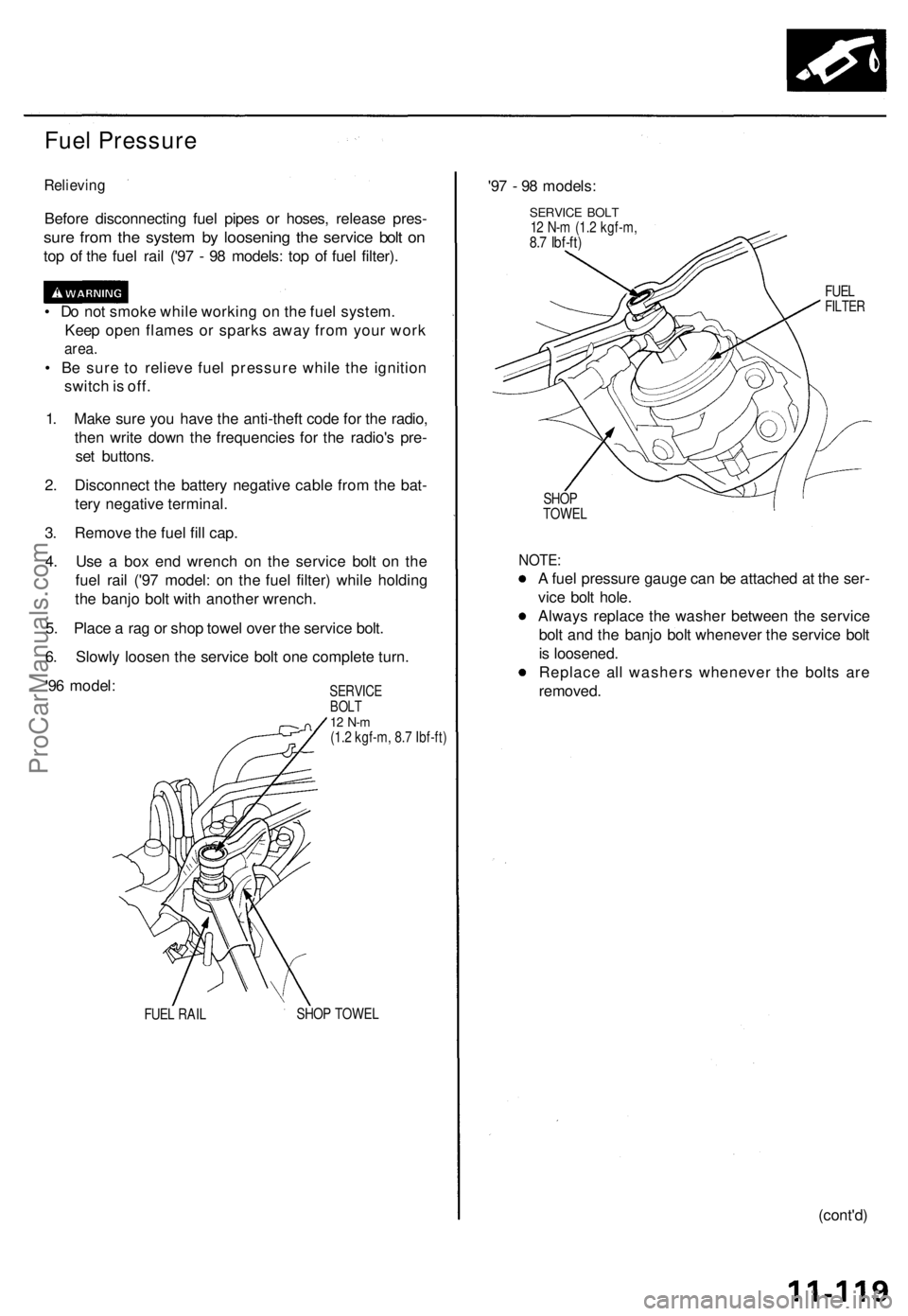
Before disconnectin g fue l pipe s o r hoses , releas e pres -
sure fro m th e syste m b y loosenin g th e servic e bol t o n
top o f th e fue l rai l ('9 7 - 9 8 models : to p o f fue l filter) .
• D o no t smok e whil e workin g o n th e fue l system .
Kee p ope n flame s o r spark s awa y fro m you r wor k
area.
• B e sur e t o reliev e fue l pressur e whil e th e ignitio n
switc h is off .
1 . Mak e sur e yo u hav e th e anti-thef t cod e fo r th e radio ,
the n writ e dow n th e frequencie s fo r th e radio' s pre -
se t buttons .
2 . Disconnec t th e batter y negativ e cabl e fro m th e bat -
ter y negativ e terminal .
3 . Remov e th e fue l fil l cap .
4 . Us e a bo x en d wrenc h o n th e servic e bol t o n th e
fue l rai l ('9 7 model : o n th e fue l filter ) whil e holdin g
th e banj o bol t wit h anothe r wrench .
5 . Plac e a ra g o r sho p towe l ove r th e servic e bolt .
6 . Slowl y loose n th e servic e bol t on e complet e turn .
'9 6 model :
SERVIC EBOLT12 N- m(1.2 kgf-m , 8. 7 Ibf-ft )
FUE L RAI L SHO
P TOWE L
'97 - 9 8 models :
SERVICE BOL T12 N- m (1. 2 kgf-m ,8.7 Ibf-ft )
FUELFILTE R
SHOP
TOWE L
NOTE:
A fue l pressur e gaug e ca n b e attache d a t th e ser -
vic e bol t hole .
Alway s replac e th e washe r betwee n th e servic e
bol t an d th e banj o bol t wheneve r th e servic e bol t
i s loosened .
Replac e al l washer s wheneve r th e bolt s ar e
removed .
(cont'd)
ProCarManuals.com
Page 306 of 1771
Checking th e Diagnosti c Troubl e Cod e (DTC )
wit h th e Servic e Chec k Connecto r an d Specia l Too l
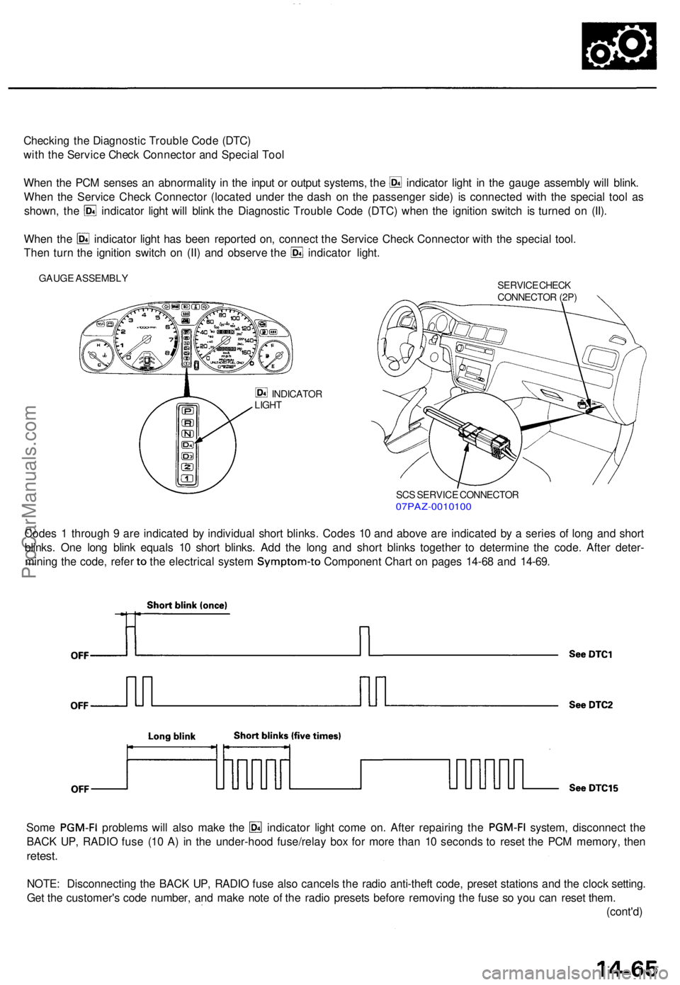
Whe n th e PC M sense s a n abnormalit y i n th e inpu t o r outpu t systems , th e indicato r ligh t i n th e gaug e assembl y wil l blink .
Whe n th e Servic e Chec k Connecto r (locate d unde r th e das h o n th e passenge r side ) i s connecte d wit h th e specia l too l a s
shown , th e indicato r ligh t wil l blin k th e Diagnosti c Troubl e Cod e (DTC ) whe n th e ignitio n switc h i s turne d o n (II) .
Whe n th e indicato r ligh t ha s bee n reporte d on , connec t th e Servic e Chec k Connecto r wit h th e specia l tool .
Then tur n th e ignitio n switc h o n (II ) an d observ e th e indicato r light .
GAUG E ASSEMBL Y
SERVICE CHEC K
CONNECTO R (2P )
INDICATO R
LIGH T
SCS SERVIC E CONNECTO R07PAZ-001010 0
Codes 1 throug h 9 ar e indicate d b y individua l shor t blinks . Code s 1 0 an d abov e ar e indicate d b y a serie s o f lon g an d shor t
blinks . On e lon g blin k equal s 1 0 shor t blinks . Ad d th e lon g an d shor t blink s togethe r t o determin e th e code . Afte r deter -
mining th e code , refe r to th e electrica l syste m Symptom-t o Component Char t o n page s 14-6 8 an d 14-69 .
Some PGM-F I problem s wil l als o mak e th e indicato r ligh t com e on . Afte r repairin g th e PGM-F I system, disconnec t th e
BAC K UP , RADI O fus e (1 0 A ) i n th e under-hoo d fuse/rela y bo x fo r mor e tha n 1 0 second s t o rese t th e PC M memory , the n
retest .
NOTE : Disconnectin g th e BAC K UP , RADI O fus e als o cancel s th e radi o anti-thef t code , prese t station s an d th e cloc k setting .
Ge t th e customer' s cod e number , an d mak e not e o f th e radi o preset s befor e removin g th e fus e s o yo u ca n rese t them .
(cont'd )
ProCarManuals.com
Page 307 of 1771
Troubleshooting Procedure s
(cont'd)
SRS component s ar e locate d i n thi s area . Revie w th e SR S componen t locations , precautions , an d procedure s i n th e SR S
( sectio n 24 ) befor e performin g repair s o r service .
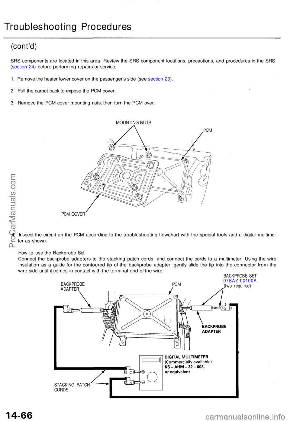
1 . Remov e th e heate r lowe r cove r o n th e passenger' s sid e (se e sectio n 20 ).
2 . Pul l th e carpe t bac k t o expos e th e PC M cover .
3 . Remov e th e PC M cove r mountin g nuts , the n tur n th e PC M over .
MOUNTIN G NUT S
PCM
PCM COVE R
4. Inspec t th e circui t o n th e PC M accordin g t o th e troubleshootin g flowchar t wit h th e specia l tool s an d a digita l multime -
te r a s shown .
How to us e th e Backprob e Se t
Connec t th e backprob e adapter s t o th e stackin g patc h cords , an d connec t th e cord s t o a multimeter . Usin g th e wir e
insulatio n a s a guid e fo r th e contoure d ti p o f th e backprob e adapter , gentl y slid e th e ti p int o th e connecto r fro m th e
wir e sid e unti l i t come s i n contac t wit h th e termina l en d o f th e wire .
BACKPROB E SE T07SAZ-00100 ABACKPROBE
ADAPTE R
STACKIN G PATC H
CORD S
PCM(tw o required )
ProCarManuals.com
Page 308 of 1771
PCM Reset Procedure
1. Make sure you have the anti-theft code for the radio, then write down the frequencies for the radio's preset buttons.
2. Turn the ignition switch OFF.
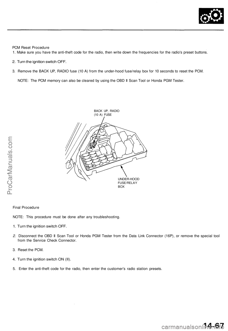
3. Remove the BACK UP, RADIO fuse (10 A) from the under-hood fuse/relay box for 10 seconds to reset the PCM.
NOTE: The PCM memory can also be cleared by using the OBD II Scan Tool or Honda PGM Tester.
BACK UP, RADIO
(10 A) FUSE
UNDER-HOOD
FUSE/RELAY
BOX
Final Procedure
NOTE: This procedure must be done after any troubleshooting.
1. Turn the ignition switch OFF.
2. Disconnect the OBD II Scan Tool or Honda PGM Tester from the Data Link Connector (16P), or remove the special tool
from the Service Check Connector.
3. Reset the PCM.
4. Turn the ignition switch ON (II).
5. Enter the anti-theft code for the radio, then enter the customer's radio station presets.ProCarManuals.com
Page 324 of 1771
Road Tes t
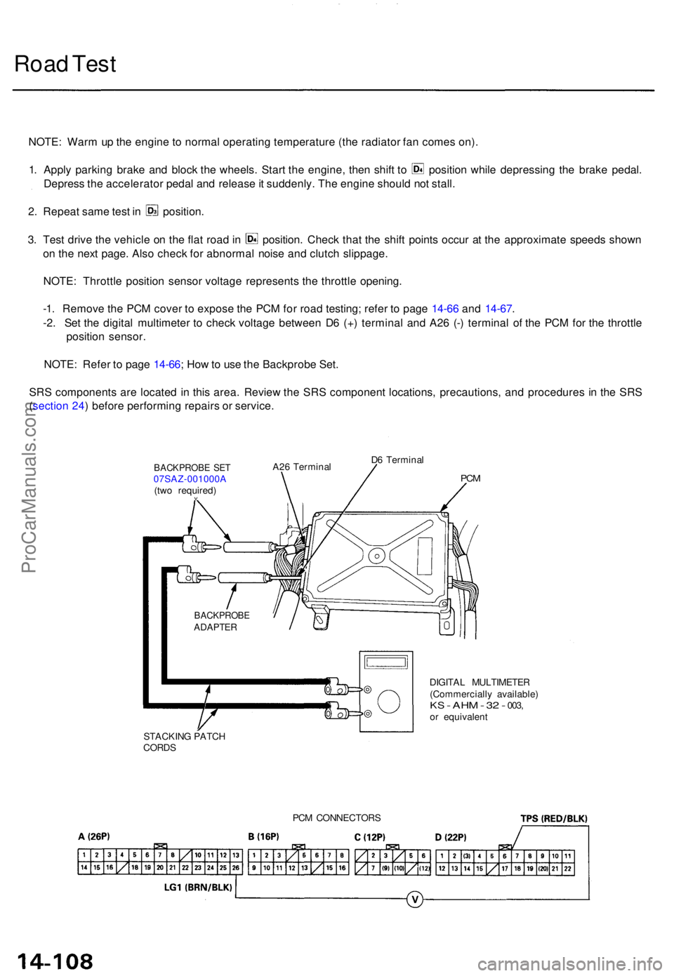
NOTE : War m u p th e engin e t o norma l operatin g temperatur e (th e radiato r fa n come s on) .
1. Appl y parkin g brak e an d bloc k th e wheels . Star t th e engine , the n shif t t o positio n whil e depressin g th e brak e pedal .
Depres s th e accelerato r peda l an d releas e it suddenly . Th e engin e shoul d no t stall .
2. Repea t sam e tes t i n position .
3. Tes t driv e th e vehicl e o n th e fla t roa d in position . Chec k tha t th e shif t point s occu r a t th e approximat e speed s show n
o n th e nex t page . Als o chec k fo r abnorma l nois e an d clutc h slippage .
NOTE : Throttl e positio n senso r voltag e represent s th e throttl e opening .
-1 . Remov e th e PC M cove r t o expos e th e PC M fo r roa d testing ; refe r t o pag e 14-6 6 an d 14-67 .
-2 . Se t th e digita l multimete r t o chec k voltag e betwee n D 6 (+ ) termina l an d A2 6 (- ) termina l o f th e PC M fo r th e throttl e
positio n sensor .
NOTE : Refe r t o pag e 14-66 ; Ho w to us e th e Backprob e Set .
SR S component s ar e locate d i n thi s area . Revie w th e SR S componen t locations , precautions , an d procedure s i n th e SR S
( sectio n 24 ) befor e performin g repair s o r service .
DIGITAL MULTIMETE R
(Commerciall y available )
KS - AH M - 32 - 003 ,or equivalen t
STACKIN G PATC H
CORDS
BACKPROB EADAPTER
BACKPROB E SE T07SAZ-001000 A
(tw o required )
v
A26 Termina l D
6 Termina lPCM
PC M CONNECTOR S
ProCarManuals.com
Page 327 of 1771
Stall Speed
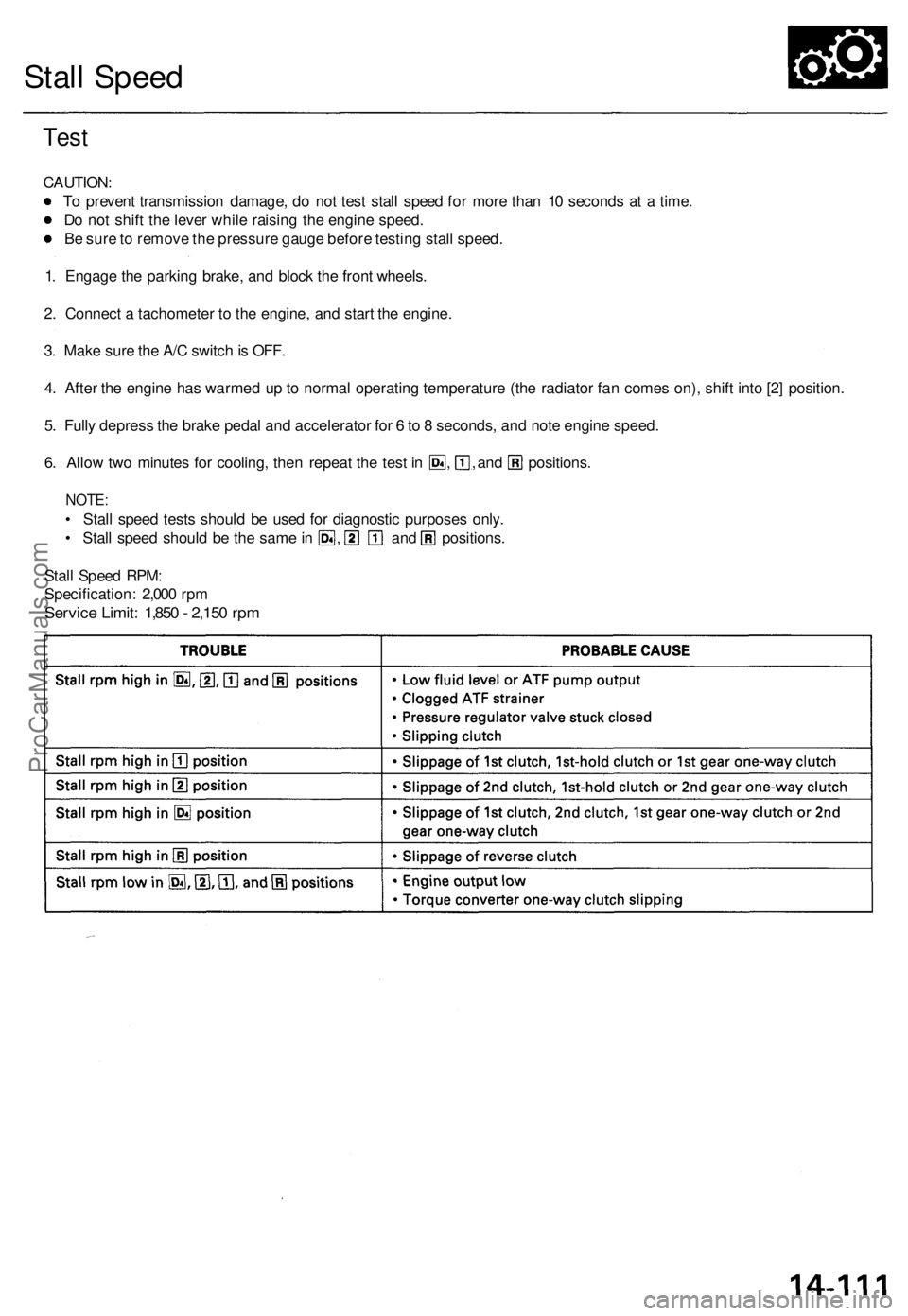
Test
CAUTION:
To prevent transmission damage, do not test stall speed for more than 10 seconds at a time.
Do not shift the lever while raising the engine speed.
Be sure to remove the pressure gauge before testing stall speed.
1. Engage the parking brake, and block the front wheels.
2. Connect a tachometer to the engine, and start the engine.
3. Make sure the A/C switch is OFF.
4. After the engine has warmed up to normal operating temperature (the radiator fan comes on), shift into [2] position.
5. Fully depress the brake pedal and accelerator for 6 to 8 seconds, and note engine speed.
6. Allow two minutes for cooling, then repeat the test in , , and positions.
NOTE:
• Stall speed tests should be used for diagnostic purposes only.
• Stall speed should be the same in , and positions.
Stall Speed RPM:
Specification: 2,000 rpm
Service Limit: 1,850 - 2,150 rpmProCarManuals.com
Page 328 of 1771
Fluid Level
Checking/Changing
Checking
NOTE: Check the fluid level with the engine at normal
operating temperature (the radiator fan comes on).
1. Park the vehicle on level ground. Turn off the
engine.
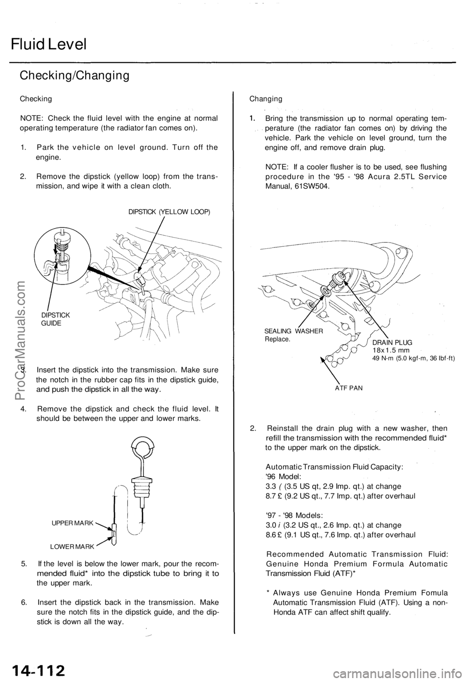
2. Remove the dipstick (yellow loop) from the trans-
mission, and wipe it with a clean cloth.
DIPSTICK (YELLOW LOOP)
DIPSTICK
GUIDE
3. Insert the dipstick into the transmission. Make sure
the notch in the rubber cap fits in the dipstick guide,
and push the dipstick in all the way.
4. Remove the dipstick and check the fluid level. It
should be between the upper and lower marks.
UPPER MARK
LOWER MARK
5. If the level is below the lower mark, pour the recom-
mended fluid* into the dipstick tube to bring it to
the upper mark.
6. Insert the dipstick back in the transmission. Make
sure the notch fits in the dipstick guide, and the dip-
stick is down all the way.
Changing
Bring the transmission up to normal operating tem-
perature (the radiator fan comes on) by driving the
vehicle. Park the vehicle on level ground, turn the
engine off, and remove drain plug.
NOTE: If a cooler flusher is to be used, see flushing
procedure in the '95 - '98 Acura 2.5TL Service
Manual, 61SW504.
SEALING WASHER
Replace.
DRAIN PLUG
18x1.5 mm
49 N-m (5.0 kgf-m, 36 Ibf-ft)
ATF PAN
2. Reinstall the drain plug with a new washer, then
refill the transmission with the recommended fluid*
to the upper mark on the dipstick.
Automatic Transmission Fluid Capacity:
'96 Model:
3.3 ( (3.5 US qt, 2.9 Imp. qt.) at change
8.7 £ (9.2 US qt., 7.7 Imp. qt.) after overhaul
'97 - '98 Models:
3.0 i (3.2 US qt., 2.6 Imp. qt.) at change
8.6 £ (9.1 US qt., 7.6 Imp. qt.) after overhaul
Recommended Automatic Transmission Fluid:
Genuine Honda Premium Formula Automatic
Transmission Fluid (ATF)*
* Always use Genuine Honda Premium Fomula
Automatic Transmission Fluid (ATF). Using a non-
Honda ATF can affect shift qualify.ProCarManuals.com
Page 331 of 1771
Pressure Testing — '96 Model
3. Slowly depress the accelerator pedal to increase
engine rpm until pressure is indicated on the pres-
sure gauge. Then release the accelerator pedal,
allowing the engine return to an idle, and measure
the pressure reading.
4. With the engine idling, depress the accelerator
pedal approximately 1/2 of its possible travel, and
increase the engine rpm until pressure is indicated
on the gauge. Then measure the highest pressure
reading obtained.
5. Repeat steps 3 and 4 for each clutch pressure being
inspected.
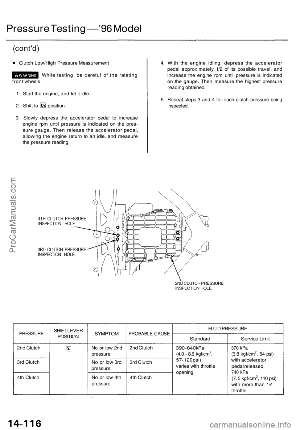
4TH CLUTCH PRESSURE
INSPECTION HOLE
3RD CLUTCH PRESSURE
INSPECTION HOLE
2ND CLUTCH PRESSURE
INSPECTION HOLE
PRESSURE
2nd Clutch
3rd Clutch
4th Clutch
SHIFT LEVER
POSITION
SYMPTOM
No or low 2nd
pressure
No or low 3rd
pressure
No or low 4th
pressure
PROBABLE CAUSE
2nd Clutch
3rd Clutch
4th Clutch
FLUID PRESSURE
Standard
390
-
840
kPa
(4.0 - 8.6 kgf/cm2,
57-120psi)
varies with throttle
opening
Service Limit
370 kPa
(3.8 kgf/cm2, 54 psi)
with accelerator
pedal released
740 kPa
(7. 5 kgf/cm2, 110 psi)
with more than 1/4
throttle
1. Start the engine, and let it idle.
(cont'd)
Clutch Low/High Pressure Measurement
2. Shift to position.
front wheels.
While testing, be careful of the ratatingProCarManuals.com