Page 759 of 1771
Rocker Arms and Shafts
Clearance Inspection
Measure both the intake rocker shafts and the exhaust
rocker shaft.
1. Measure diameter of shaft at first rocker location.
Inspect rocker arm
face for wear.
MICROMETER
2. Zero gauge to shaft diameter.
CYLINDER BORE
GAUGE
MICROMETER
3. Measure the inside diameter of the rocker arm, and
check for out-of-round condition.
Rocker Arm-to-Shaft Clearance:
Standard (New):
Intake: 0.017-0.050 mm
(0.0007 - 0.0020 in)
Exhaust: 0.018 - 0.054 mm
(0.0007 - 0.0021 in)
Service Limit: 0.08 mm (0.003 in)
Inspect rocker arm
face for wear.
Repeat for all rockers.
— If over limit, replace rocker shaft and all overtol-
erance rocker arms.ProCarManuals.com
Page 763 of 1771

Valve Guides
Valve Movement
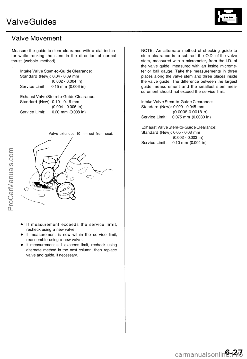
Measure the guide-to-stem clearance with a dial indica-
tor while rocking the stem in the direction of normal
thrust (wobble method).
Intake Valve Stem-to-Guide Clearance:
Standard (New): 0.04 - 0.09 mm
(0.002 - 0.004 in)
Service Limit: 0.15 mm (0.006 in)
Exhaust Valve Stem-to-Guide Clearance:
Standard (New): 0.10 - 0.16 mm
(0.004 - 0.006 in)
Service Limit: 0.20 mm (0.008 in)
Valve extended 10 mm out from seat.
If
measurement exceeds
the
service
limit,
recheck using a new valve.
If measurement is now within the service limit,
reassemble using a new valve.
If measurement still exceeds limit, recheck using
alternate method in the next column, then replace
valve and guide, if necessary.
NOTE: An alternate method of checking guide to
stem clearance is to subtract the O.D. of the valve
stem, measured with a micrometer, from the I.D. of
the valve guide, measured with an inside microme-
ter or ball gauge. Take the measurements in three
places along the valve stem and three places inside
the valve guide. The difference between the largest
guide measurement and the smallest stem mea-
surement should not exceed the service limit.
Intake Valve Stem-to-Guide Clearance:
Standard (New): 0.020 - 0.045 mm
(0.0008-0.0018 in)
Service Limit: 0.075 mm (0.0030 in)
Exhaust Valve Stem-to-Guide Clearance:
Standard (New): 0.05 - 0.08 mm
(0.002 - 0.003 in)
Service Limit: 0.10 mm (0.004 in)ProCarManuals.com
Page 781 of 1771

Main Bearings
Clearance
1. To check main bearing-to-journal oil clearance,
remove the main caps and bearing halves.
2. Clean each main journal and bearing half with a
clean shop towel.
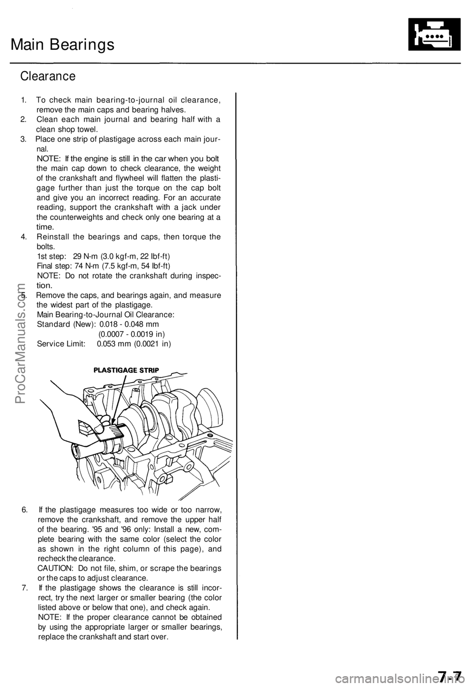
3. Place one strip of plastigage across each main jour-
nal.
NOTE: If the engine is still in the car when you bolt
the main cap down to check clearance, the weight
of the crankshaft and flywheel will flatten the plasti-
gage further than just the torque on the cap bolt
and give you an incorrect reading. For an accurate
reading, support the crankshaft with a jack under
the counterweights and check only one bearing at a
time.
4. Reinstall the bearings and caps, then torque the
bolts.
1st step: 29 N-m (3.0 kgf-m, 22 Ibf-ft)
Final step: 74 N-m (7.5 kgf-m, 54 Ibf-ft)
NOTE: Do not rotate the crankshaft during inspec-
tion.
5. Remove the caps, and bearings again, and measure
the widest part of the plastigage.
Main Bearing-to-Journal Oil Clearance:
Standard (New): 0.018 - 0.048 mm
(0.0007 - 0.0019 in)
Service Limit: 0.053 mm (0.0021 in)
6. If the plastigage measures too wide or too narrow,
remove the crankshaft, and remove the upper half
of the bearing. '95 and '96 only: Install a new, com-
plete bearing with the same color (select the color
as shown in the right column of this page), and
recheck the clearance.
CAUTION: Do not file, shim, or scrape the bearings
or the caps to adjust clearance.
7. If the plastigage shows the clearance is still incor-
rect, try the next larger or smaller bearing (the color
listed above or below that one), and check again.
NOTE: If the proper clearance cannot be obtained
by using the appropriate larger or smaller bearings,
replace the crankshaft and start over.ProCarManuals.com
Page 784 of 1771

Connecting Rod Bearings
Clearance
1. Remove the connecting rod cap and bearing half.
2. Clean the crankshaft rod journal and bearing half
with a clean shop towel.
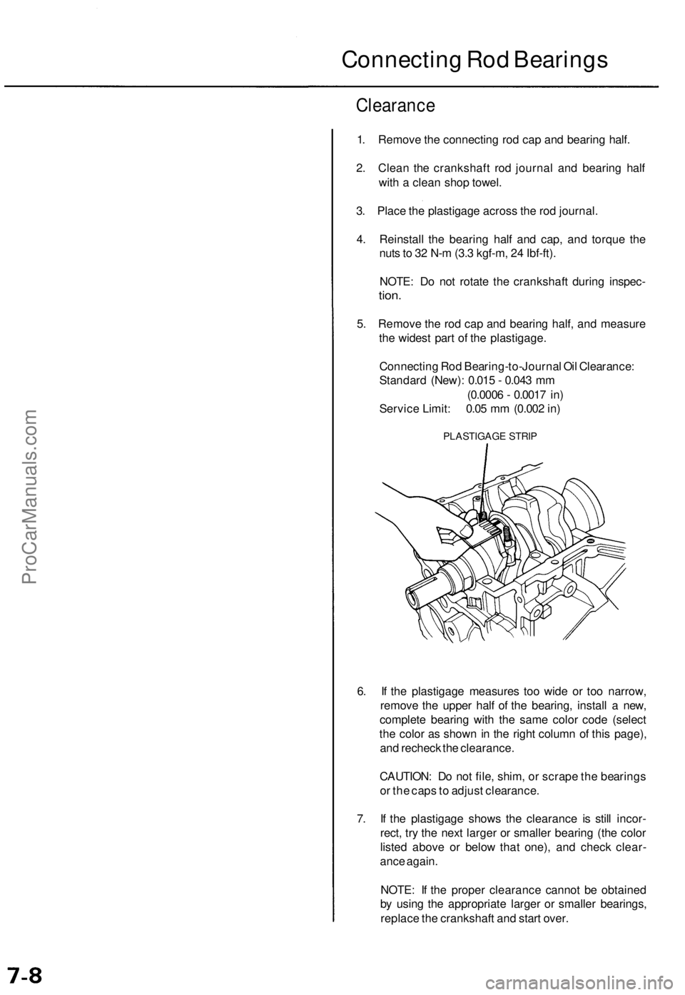
3. Place the plastigage across the rod journal.
4. Reinstall the bearing half and cap, and torque the
nuts to 32 N-m (3.3 kgf-m, 24 Ibf-ft).
NOTE: Do not rotate the crankshaft during inspec-
tion.
5. Remove the rod cap and bearing half, and measure
the widest part of the plastigage.
Connecting Rod Bearing-to-Journal Oil Clearance:
Standard (New): 0.015 - 0.043 mm
(0.0006 - 0.0017 in)
Service Limit: 0.05 mm (0.002 in)
PLASTIGAGE STRIP
6. If the plastigage measures too wide or too narrow,
remove the upper half of the bearing, install a new,
complete bearing with the same color code (select
the color as shown in the right column of this page),
and recheck the clearance.
CAUTION: Do not file, shim, or scrape the bearings
or the caps to adjust clearance.
7. If the plastigage shows the clearance is still incor-
rect, try the next larger or smaller bearing (the color
listed above or below that one), and check clear-
ance again.
NOTE: If the proper clearance cannot be obtained
by using the appropriate larger or smaller bearings,
replace the crankshaft and start over.ProCarManuals.com
Page 807 of 1771
The numbers in the middle of the API Service label tell
you the oil's SAE viscosity or weight. Select the oil for
your car according to this chart:
An oil with a viscosity of 5W - 30 is preferred for
improved fuel economy and year-round protection in the
car. You may use a 10W - 30 oil if the climate in your area
is limited to the temperature range shown on the chart.
4. Fill the engine with oil up to the specified level, run
the engine for more than three minutes, then check
for oil leakage.ProCarManuals.com
Page 833 of 1771
Component Location s
Index (cont'd )
PRIMARY HEATE D OXYGE N SENSO R (PRIMAR Y HO2S )
SECONDAR Y HEATE D OXYGE N SENSO R (SECONDAR Y HO2S )
SERVICE CHEC K CONNECTO R (2P )
Troubleshootin g procedures , pag e 11-3 2
PGM-F I
MAI N RELA Y
Rela y Testing , pag e 11-13 1
Troubleshooting , pag e 11-13 2
TCM
ENGIN E CONTRO L MODUL E (ECM )
Troubleshooting , pag e 11-5 2
DAT
A LIN K CONNECTO R (16P )
Troubleshootin gprocedures, pag e 11-3 2
For Troubleshooting of DTC related components, see chart on page 11-44.
ProCarManuals.com
Page 861 of 1771

Troubleshooting
Troubleshootin g Procedure s
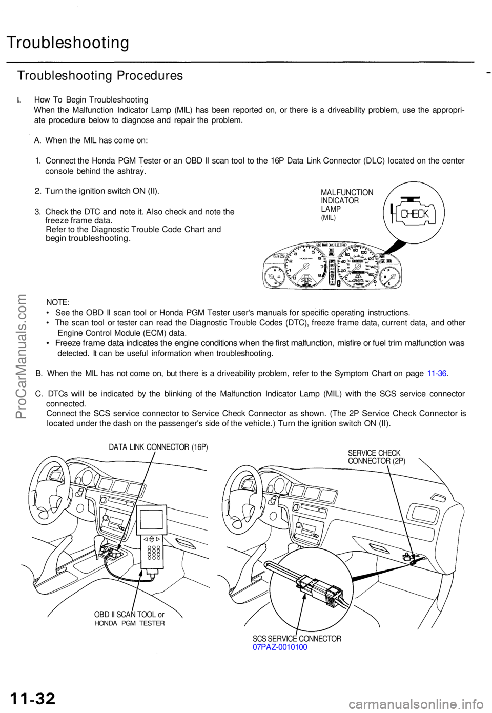
How T o Begi n Troubleshootin g
Whe n th e Malfunctio n Indicato r Lam p (MIL ) ha s bee n reporte d on , o r ther e i s a driveabilit y problem , us e th e appropri -
at e procedur e belo w to diagnos e an d repai r th e problem .
A . Whe n th e MI L ha s com e on :
1 . Connec t th e Hond a PG M Teste r o r a n OB D II sca n too l t o th e 16 P Dat a Lin k Connecto r (DLC ) locate d o n th e cente r
consol e behin d th e ashtray .
2. Tur n th e ignitio n switc h O N (II) .
3. Chec k th e DT C an d not e it . Als o chec k an d not e th e
freez e fram e data .
Refe r t o th e Diagnosti c Troubl e Cod e Char t an d
begi n troubleshooting .
MALFUNCTIONINDICATOR
LAM P
(MIL)
NOTE :
• Se e th e OB D II sca n too l o r Hond a PG M Teste r user' s manual s fo r specifi c operatin g instructions .
• Th e sca n too l o r teste r ca n rea d th e Diagnosti c Troubl e Code s (DTC) , freez e fram e data , curren t data , an d othe r
Engin e Contro l Modul e (ECM ) data .
• Freez e fram e dat a indicate s th e engin e condition s whe n th e firs t malfunction , misfir e o r fue l tri m malfunctio n wa s
detected . I t ca n b e usefu l informatio n whe n troubleshooting .
B . Whe n th e MI L ha s no t com e on , bu t ther e i s a driveabilit y problem , refe r t o th e Sympto m Char t o n pag e 11-36 .
C. DTC s will be indicate d by th e blinkin g of th e Malfunctio n Indicato r Lam p (MIL ) with the SC S servic e connecto r
connected .
Connec t th e SC S servic e connecto r t o Servic e Chec k Connecto r a s shown . (Th e 2 P Servic e Chec k Connecto r i s
locate d unde r th e das h o n th e passenger' s sid e o f th e vehicle. ) Tur n th e ignitio n switc h O N (II) .
DAT A LIN K CONNECTO R (16P )
OB D II SCA N TOO L o r
HOND A PG M TESTE R
SERVICE CHEC KCONNECTO R (2P )
SC S SERVIC E CONNECTO R
07PAZ-001010 0
ProCarManuals.com
Page 862 of 1771
II. Engine Control Module (ECM) Reset Procedure
Either of the following actions will reset the ECM.
• Use the OBD II scan tool or Honda PGM Tester to clear the ECM's memory.
NOTE: See the OBD II scan tool or Honda PGM Tester user's manuals for specific operating instructions.
• Turn the ignition switch OFF. Remove the BACK UP RADIO (10 A) fuse from the under-hood fuse/relay box for
10 seconds.
BACK UP RADIO
(10 A) FUSE
UNDER-HOOD
FUSE/RELAY
BOX
III. Final Procedure (this procedure must be done after any troubleshooting)
1. Remove the SCS Service Connector if it is connected.
NOTE: If the SCS service connector is connected and there are no DTCs stored in the ECM, the MIL will stay
on when the ignition switch is turned ON (II).
2. Do the ECM Reset Procedure.
3. Turn the ignition switch OFF.
4. Disconnect the OBD II scan tool or Honda PGM Tester from the Data Link Connector (16P).ProCarManuals.com