Page 1034 of 1771
ATF Pump
Inspection
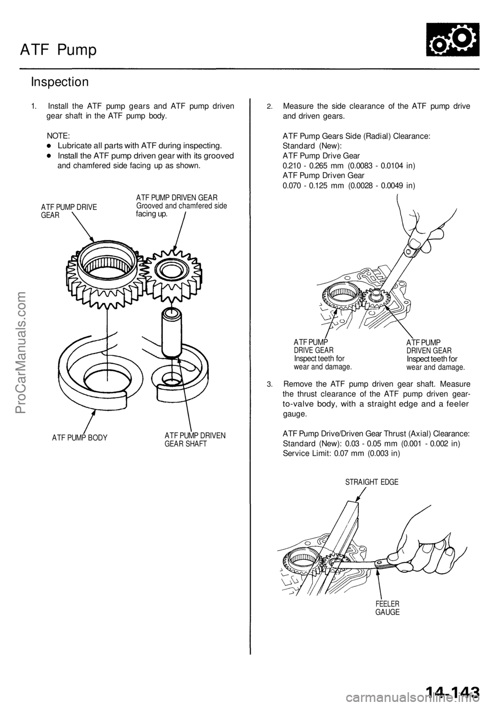
1. Install the ATF pump gears and ATF pump driven
gear shaft in the ATF pump body.
NOTE:
Lubricate all parts with ATF during inspecting.
Install the ATF pump driven gear with its grooved
and chamfered side facing up as shown.
ATF PUMP DRIVE
GEAR
ATF PUMP DRIVEN GEAR
Grooved and chamfered side
facing up.
ATF PUMP BODY
ATF PUMP DRIVEN
GEAR SHAFT
2.
3.
Measure the side clearance of the ATF pump drive
and driven gears.
ATF Pump Gears Side (Radial) Clearance:
Standard (New):
ATF Pump Drive Gear
0.210 - 0.265 mm (0.0083 - 0.0104 in)
ATF Pump Driven Gear
0.070 - 0.125 mm (0.0028 - 0.0049 in)
ATF PUMP
DRIVE GEAR
Inspect teeth for
wear and damage.
ATF PUMP
DRIVEN GEAR
Inspect teeth for
wear and damage.
Remove the ATF pump driven gear shaft. Measure
the thrust clearance of the ATF pump driven gear-
to-valve body, with a straight edge and a feeler
gauge.
ATF Pump Drive/Driven Gear Thrust (Axial) Clearance:
Standard (New): 0.03 - 0.05 mm (0.001 - 0.002 in)
Service Limit: 0.07 mm (0.003 in)
STRAIGHT EDGE
FEELER
GAUGEProCarManuals.com
Page 1056 of 1771
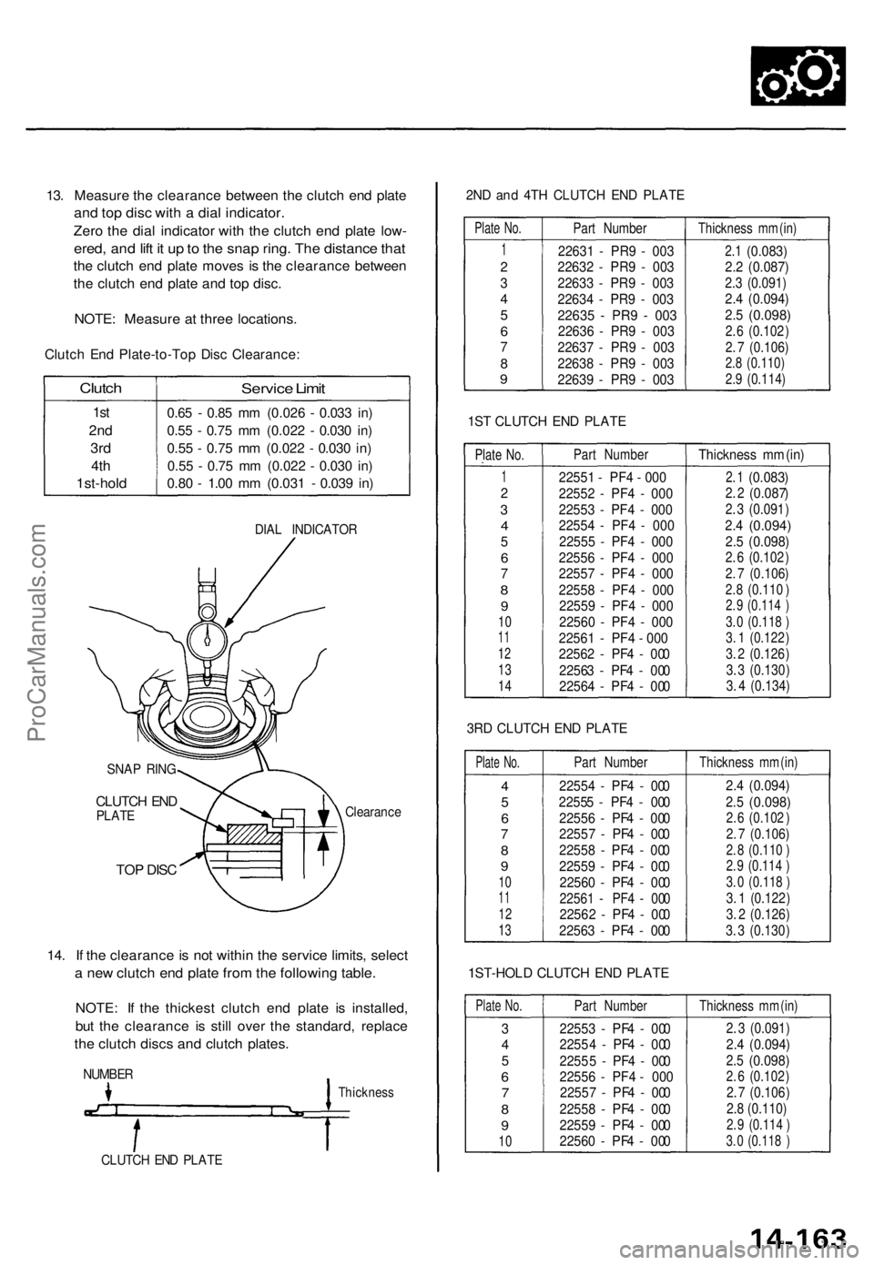
13. Measur e th e clearanc e betwee n th e clutc h en d plat e
and to p dis c wit h a dia l indicator .
Zero th e dia l indicato r wit h th e clutc h en d plat e low -
ered , an d lif t i t u p to th e sna p ring . Th e distanc e tha t
the clutc h en d plat e move s i s th e clearanc e betwee n
the clutc h en d plat e an d to p disc .
NOTE : Measur e a t thre e locations .
Clutch En d Plate-to-To p Dis c Clearance :
Clutch
1st
2n d
3rd
4th
1st-hol d
Service Limi t
0.65 - 0.8 5 m m (0.02 6 - 0.03 3 in )
0.5 5 - 0.7 5 m m (0.02 2 - 0.03 0 in )
0.5 5 - 0.7 5 m m (0.02 2 - 0.03 0 in )
0.5 5 - 0.7 5 m m (0.02 2 - 0.03 0 in )
0.8 0 - 1.0 0 m m (0.03 1 - 0.03 9 in )
DIA L INDICATO R
SNA P RIN G
CLUTC H EN DPLAT E Clearanc
e
TOP DIS C
14. I f th e clearanc e is no t withi n th e servic e limits , selec t
a ne w clutc h en d plat e fro m th e followin g table .
NOTE : I f th e thickes t clutc h en d plat e i s installed ,
but th e clearanc e i s stil l ove r th e standard , replac e
the clutc h disc s an d clutc h plates .
NUMBE R
Thicknes s
CLUTCH EN D PLAT E
2ND an d 4T H CLUTC H EN D PLAT E
Plate No.
1
2
34
5
67
89
Part Number
22631 - PR9 - 003
22632 - PR9 - 003
22633 - PR9 - 003
22634 - PR9 - 003
22635 - PR9 - 00322636 - PR9 - 003
22637 - PR9 - 003
22638 - PR9 - 003
22639 - PR9 - 003
Thickness mm (in)
2.1 (0.083)
2.2 (0.087)
2.3 (0.091)2.4 (0.094)
2.5
(0.098)
2 .6 (0.10 2)
2. 7 (0.106)2.8 (0.110)
2.9 (0.114)
1S T CLUTC H EN D PLAT E
Plate No.
12
34
5
67
8
9
1011
12
13
14
Part Number
22551 - PF4 - 000
22552 - PF4 - 000
22553 - PF4 - 000
22554 - PF4 - 000
22555 - PF4 - 000
22556 - PF4 - 000
22557 - PF4 - 000
22558 - PF4 - 000
22559 - PF4 - 000
22560 - PF4 - 000
22561 - PF4 - 000
22562 - P F4 - 0 00
22563 - PF4 - 000
22564 - PF4 - 000 Thickness
mm (in)2 .1 (0.08 3)2. 2 (0.087)
2. 3 (0.091)
2.4 (0.094)
2.5 (0.098)2. 6 (0.102 )
2. 7 (0.106)
2.8 (0.110 )2. 9 (0.114 )
3. 0 (0.118 )3. 1 (0.122 )
3. 2 (0.126)
3. 3 (0.130)
3. 4 (0.134)
3R D CLUTC H EN D PLAT E
Plate No.
4
5
67
89
101 1
12
13
Part Number
22554 - PF4 - 000
22555 - PF4 - 000 22556 - PF4 - 000
22557 - PF4 - 000
22558 - PF4 - 000
22559 - PF4 - 00022560 - PF4 - 000
22561 - PF4 - 00022562 - PF4 - 000
22563 - PF4 - 000
Thickness mm (in)
2.4 (0.094)
2.5 (0.098)2. 6 (0.102 )
2. 7 (0.106)
2. 8 (0.110 )2. 9 (0.114 )
3. 0 (0.118 )
3. 1 (0.122)
3. 2 (0.126)
3. 3 (0.130 )
1ST-HOL D CLUTC H EN D PLAT E
Plate No.
34
5
67
8
9
10
Part Number
22553 - PF4 - 000
2255 4 - PF4 - 000
2255 5 - PF4 - 000
22556 - PF4 - 000
22557 - PF4 - 000
22558 - PF4 - 000
22559 - PF4 - 000
22560 - PF4 - 000
Thickness mm (in)
2. 3 (0.091)
2.4 (0.094)
2.5 (0.098)2. 6 (0.102 )
2. 7 (0.106 )
2.8 (0.110)
2. 9 (0.114 )
3. 0 (0.118 )
ProCarManuals.com
Page 1107 of 1771
Backlash Inspectio n
1. Remov e th e tapere d rolle r bearing s (se e pag e 15-14 ).
2 . Instal l th e lef t driveshaf t an d th e intermediat e shaf t
i n th e sid e gears .
3 . Measur e th e backlas h o f bot h pinio n gears .
Standard: 0.05-0.15 mm (0.002-0.006 in)
Service Limit: 0.30 mm (0.012 in)
PINION GEAR S
If th e backlas h exceed s th e servic e limit , replac e th e
differentia l carrier .
Ring Gea r Replacemen t
1. Remov e th e bolt s in a crisscros s pattern , i n severa l
steps, an d remov e th e rin g gear .
12 x 1. 0 m m135 N- m (13. 8 kgf-m ,
99. 8 Ibf-ft )
DIFFERENTIAL
CARRIER
RINGGEA R
2. Instal l th e rin g gea r b y tightenin g th e bolt s i n a criss -
cros s pattern , i n severa l steps . I f th e bolt s ar e
difficul t t o tighten , mak e sur e tha t th e rin g gea r i s
goin g o n t o th e differentia l carrie r correctly .
ProCarManuals.com
Page 1144 of 1771
Component Location s
Index
NOTE :
• I f a n intac t airba g assembl y ha s bee n remove d fro m a scrappe d vehicl e o r ha s bee n foun d defectiv e o r damage d dur -
in g transit , storag e o r service , i t shoul d b e deploye d (se e sectio n 24 ).
• Befor e removin g th e steerin g gearbox , remov e th e driver' s airba g assembl y an d steerin g wheel .
• Afte r installin g th e steerin g gearbox , chec k th e whee l alignmen t an d adjus t i f necessary .
SR S component s ar e locate d in thi s area . Revie w th e SR S componen t locations , precautions , an d procedure s in th e SR S
( sectio n 24 ) befor e performin g repair s o r service .
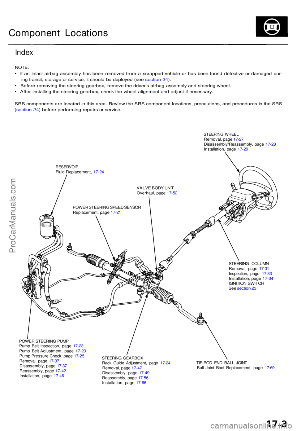
STEERIN G WHEE LRemoval , pag e 17-2 7
Disassembly/Reassembly , pag e 17-2 8
Installation , pag e 17-2 9
RESERVOI RFluid Replacement , 17-2 4
VALVE BOD Y UNI T
Overhaul , pag e 17-5 2
POWE R STEERIN G SPEE D SENSO R
Replacement , pag e 17-2 1
STEERING COLUM N
Removal , pag e 17-3 1
Inspection , pag e 17-3 3
Installation , pag e 17-3 4IGNITIO N SWITC HSee sectio n 2 3
POWE R STEERIN G PUM P
Pum p Bel t Inspection , pag e 17-2 3
Pum p Bel t Adjustment , pag e 17-2 3
Pum p Pressur e Check , pag e 17-2 5
Removal , pag e 17-3 7
Disassembly , pag e 17-3 7
Reassembly , pag e 17-4 2
Installation , pag e 17-4 6
STEERIN G GEARBO XRack Guid e Adjustment , pag e 17-2 4
Removal , pag e 17-4 7
Disassembly , pag e 17-4 9
Reassembly , pag e 17-5 6
Installation , pag e 17-6 6 TIE-RO
D EN D BAL L JOIN T
Bal l Join t Boo t Replacement , pag e 17-6 9
ProCarManuals.com
Page 1171 of 1771
Steering Whee l
Disassembly/Reassembl y
Store a remove d airba g assembl y with
the pa d surfac e up . I f th e airba g i s improperl y store d
face down , accidenta l deploymen t coul d prope l th e uni t
with enoug h forc e to caus e seriou s injury .
NOTE: I f a n intac t airba g assembl y ha s bee n remove d
from a scrappe d vehicle , o r ha s bee n foun d defectiv e o r
damage d durin g transit , storag e o r service , i t shoul d b e
deploye d (se e sectio n 24 ).
AIRBA G ASSEMBL Y
TORX BOL T10N-m d.Okgfm , 7 Ibf-ft)
CAUTION :
• Carefull y inspec t th e airba g assembl y befor e install -
ing. D o no t instal l a n airba g assembl y tha t show s
signs o f bein g droppe d o r improperl y handled , suc h
as dents , crack s o r deformation .
• D o no t disassembl e or tampe r with the airba g assem -
bly.
STEERIN G WHEE L
HOR N CONTAC T PLAT E
COVER
CRUIS E CONTRO L SWITCHE S
COVER
ACCESS PANE L
17-28
Steering Wheel
ProCarManuals.com
Page 1268 of 1771
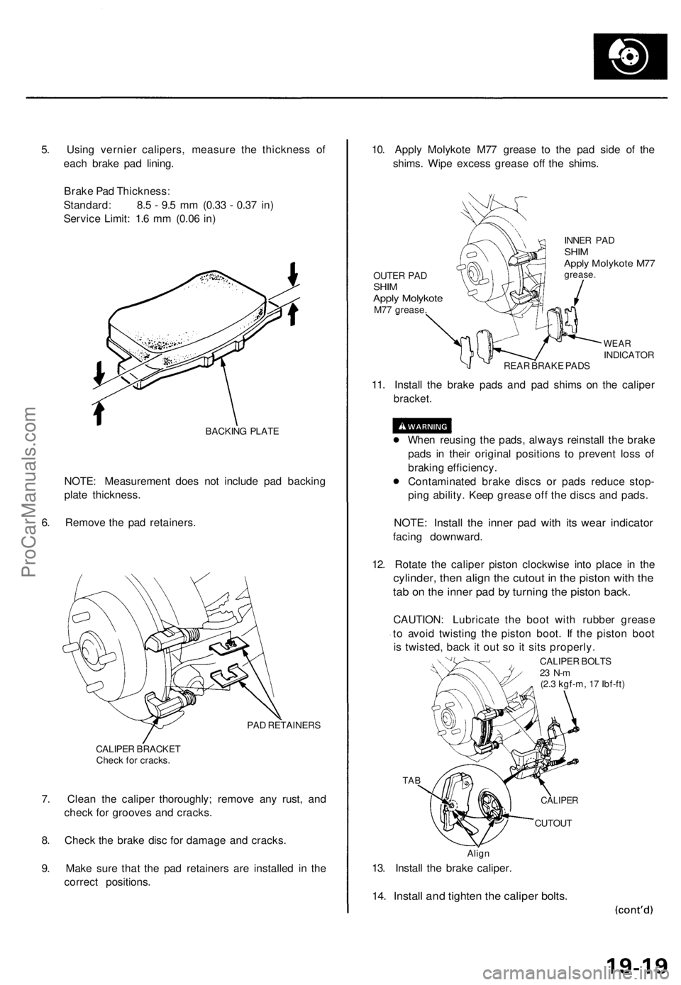
5. Using vernier calipers, measure the thickness of
each brake pad lining.
Brake Pad Thickness:
Standard: 8.5 - 9.5 mm (0.33 - 0.37 in)
Service Limit: 1.6 mm (0.06 in)
BACKING PLATE
NOTE: Measurement does not include pad backing
plate thickness.
6. Remove the pad retainers.
PAD RETAINERS
CALIPER BRACKET
Check for cracks.
7. Clean the caliper thoroughly; remove any rust, and
check for grooves and cracks.
8. Check the brake disc for damage and cracks.
9. Make sure that the pad retainers are installed in the
correct positions.
10. Apply Molykote M77 grease to the pad side of the
shims. Wipe excess grease off the shims.
OUTER PAD
SHIM
Apply Molykote
M77 grease.
INNER PAD
SHIM
Apply Molykote M77
grease.
WEAR
INDICATOR
REAR BRAKE PADS
11. Install the brake pads and pad shims on the caliper
bracket.
When reusing the pads, always reinstall the brake
pads in their original positions to prevent loss of
braking efficiency.
Contaminated brake discs or pads reduce stop-
ping ability. Keep grease off the discs and pads.
NOTE: Install the inner pad with its wear indicator
facing downward.
12. Rotate the caliper piston clockwise into place in the
cylinder, then align the cutout in the piston with the
tab on the inner pad by turning the piston back.
CAUTION: Lubricate the boot with rubber grease
to avoid twisting the piston boot. If the piston boot
is twisted, back it out so it sits properly.
CALIPER BOLTS
23 N-m
(2.3 kgf-m, 17 Ibf-ft)
TAB
CUTOUT
Align
13. Install the brake caliper.
14. Install and tighten the caliper bolts.
CALIPERProCarManuals.com
Page 1280 of 1771
Brake Hoses/Lines
Inspection ('95, '96 models)
1. Inspect the brake hoses for damage, deterioration, leaks, interference and twisting.
2. Check the brake lines for damage, rusting and leakage. Also check for bent brake lines.
3. Check for leaks at hose and line joints and connections, and retighten if necessary.
4. Check the master cylinder and ABS modulator unit for damage and leakage.
CAUTION: Replace the brake hose clip whenever the brake hose is serviced.
MASTER CYLINDER-to-BRAKE LINE
19 N-m (1.9 kgf-m, 14 Ibf-ft)
BRAKE LINE-to-MODULATOR UNIT
19 N-m (1.9 kgf-m, 14 Ibf-ft)
BLEED SCREW
9 N-m (0.9 kgf-m, 6.5 Ibf-ft)
BRAKE HOSE-to-CALIPER
(BANJO BOLT)
34 N-m (3.5 kgf-m, 25 Ibf-ft)
BRAKE HOSE-to-CALIPER
(BANJO BOLT)
34 N-m (3.5 kgf-m, 25 Ibf-ft)
BLEED SCREW
9 N-m (0.9 kgf-m, 6.5 Ibf-ft)
BRAKE LINE-to-BRAKE HOSE
15 N-m (1.5 kgf-m, 11 Ibf-ft)
BRAKE LINE-to-4-WAY JOINT
19 N-m (1.9 kgf-m, 14 Ibf-ft)
BRAKE LINE-to-BRAKE HOSE
15 N-m (1.5 kgf-m, 11 Ibf-ft)ProCarManuals.com
Page 1281 of 1771
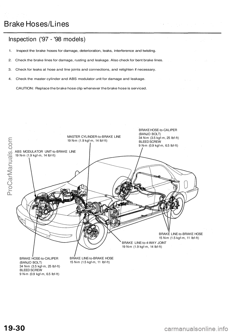
Brake Hoses/Lines
Inspection ('97 - '98 models)
1. Inspect the brake hoses for damage, deterioration, leaks, interference and twisting.
2. Check the brake lines for damage, rusting and leakage. Also check for bent brake lines.
3. Check for leaks at hose and line joints and connections, and retighten if necessary.
4. Check the master cylinder and ABS modulator unit for damage and leakage.
CAUTION: Replace the brake hose clip whenever the brake hose is serviced.
MASTER CYLINDER-to-BRAKE LINE
19 N-m (1.9 kgf-m, 14 Ibf-ft)
ABS MODULATOR UNIT-to-BRAKE LINE
19 N-m (1.9 kgf-m, 14 Ibf-ft)
BRAKE HOSE-to-CALIPER
(BANJO BOLT)
34 N-m (3.5 kgf-m, 25 Ibf-ft)
BLEED SCREW
9 N-m (0.9 kgf-m, 6.5 Ibf-ft)
BRAKE LINE-to-BRAKE HOSE
15 N-m (1.5 kgf-m, 11 Ibf-ft)
BRAKE LINE-to-4-WAY JOINT
19 N-m (1.9 kgf-m, 14 Ibf-ft)
BRAKE HOSE-to-CALIPER
(BANJO BOLT)
34 N-m (3.5 kgf-m, 25 Ibf-ft)
BLEED SCREW
9 N-m (0.9 kgf-m, 6.5 Ibf-ft)
BRAKE LINE-to-BRAKE HOSE
15 N-m (1.5 kgf-m, 11 Ibf-ft)ProCarManuals.com