Page 1554 of 1771
Electrical Switc h Replacemen t
SRS component s ar e locate d in thi s area . Revie w th e SR S
componen t locations , precautions , an d procedure s in th e
SR S (sectio n 24 ) befor e performin g repair s o r service .
1 . Mak e sur e yo u hav e th e anti-thef t cod e fo r th e radio ,
the n writ e dow n th e frequencie s fo r th e radio' s pre -
set buttons .
2. Disconnec t th e batter y negativ e cable , the n discon -
nec t th e positiv e cable , an d wai t a t leas t thre e min -
utes .
3 . Remov e th e dashboar d lowe r cove r an d kne e bolste r
(se e pag e 23-67 ).
4 . Remov e th e steerin g colum n cover s (se e pag e 23-67 ).
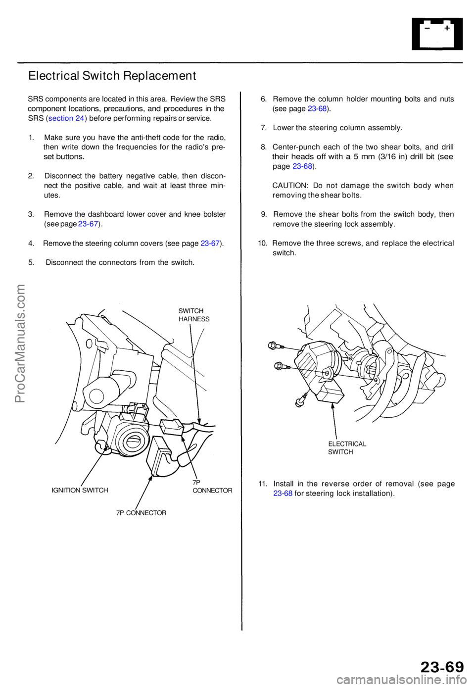
5 . Disconnec t th e connector s fro m th e switch .
SWITCHHARNES S
IGNITION SWITC H7PCONNECTO R
7 P CONNECTO R
6. Remov e th e colum n holde r mountin g bolt s an d nut s
(se e pag e 23-68 ).
7 . Lower the steerin g colum n assembly .
8 . Center-punc h eac h o f th e tw o shea r bolts , an d dril l
their head s of f wit h a 5 mm (3/1 6 in ) dril l bi t (se e
pag e 23-68 ).
CAUTION : D o no t damag e th e switc h bod y whe n
removin g th e shea r bolts .
9 . Remov e th e shea r bolt s fro m th e switc h body , the n
remov e th e steerin g loc k assembly .
10 . Remov e th e thre e screws , an d replac e th e electrica l
switch .
ELECTRICA LSWITCH
11. Instal l i n th e revers e orde r o f remova l (se e pag e
23-6 8 fo r steerin g loc k installation) .
ProCarManuals.com
Page 1561 of 1771
Starting System
Armature Inspection and Test
1.
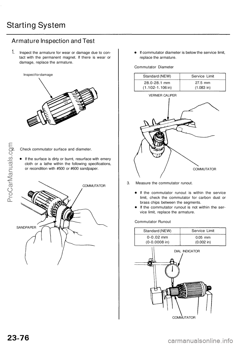
Inspect the armature for wear or damage due to con-
tact with the permanent magnet. If there is wear or
damage, replace the armature.
Inspect for damage
2. Check commutator surface and diameter.
If the surface is dirty or burnt, resurface with emery
cloth or a lathe within the following specifications,
or recondition with #500 or #600 sandpaper.
COMMUTATOR
SANDPAPER
If commutator diameter is below the service limit,
replace the armature.
Commutator Diameter
Standard (NEW)
28.0-28.1 mm
(1.102-1.
106 in)
Service Limit
27.5
mm
(1.083 in)
VERNIER CALIPER
COMMUTATOR
3. Measure the commutator runout.
If the commutator runout is within the service
limit, check the commutator for carbon dust or
brass chips between the segments.
If the commutator runout is not within the ser-
vice limit, replace the armature.
Commutator Runout
Standard (NEW)
0-0.02 mm
(0-0.0008 in)
Service Limit
0.05
mm
(0.002 in)
DIAL INDICATOR
COMMUTATORProCarManuals.com
Page 1562 of 1771
4.
Check for mica depth. If necessary, undercut the mica
with a hacksaw blade to achieve proper depth. If the
service limit cannot be maintained, replace the arma-
ture.
HIGH
MICA
NOT GOOD
GOOD
MICA DEPTH
Commutator Mica Depth
Standard (NEW)
0.4-0.5 mm
(0.016 -0.020 in)
Service Limit
0.15
mm
(0.006 in)
5.
Check for continuity between the segments of the
commutator. If an open circuit exists between any
segments, replace the armature.
COMMUTATOR SEGMENT
6.
Place the armature on an armature tester. Hold a
hacksaw blade on the armature core. If the blade is
attracted to the core or vibrates while the core is
turned, the armature is shorted. Replace the arma-
ture.
ARMATURE TESTER
HACKSAW BLADE
ARMATURE
7. Check with an ohmmeter that no continuity exists
between the commutator and armature coil core,
and between the commutator and armature shaft. If
continuity exists, replace the armature.
SHAFT
COIL CORE
COMMUTATORProCarManuals.com
Page 1568 of 1771
Ignition Syste m
Ignition Timin g Inspectio n
SRS component s ar e locate d in thi s area . Revie w th e SR S
componen t locations , precautions , an d procedure s i n th e
SR S (sectio n 24 ) befor e performin g repair s o r service .
1.
2 .
Star t th e engine . Hol d th e engine at 3,00 0 rp m wit h
no loa d (shif t leve r i n o r position ) unti l th e
radiato r fa n come s on , the n le t i t idle .
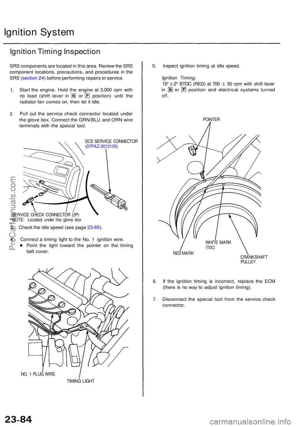
Pul l ou t th e servic e chec k connecto r locate d unde r
th e glov e box . Connec t th e GRN/BL U an d OR N wir e
terminal s wit h th e specia l tool .
SCS SERVIC E CONNECTO R
( 07PAZ-0010100 )
SERVIC E CHEC K CONNECTO R (2P)
NOTE : Locate d unde r th e glov e bo x
3. Chec k th e idl e spee d (se e pag e 23-85 ).
4 . Connec t a timin g ligh t t o th e No . 1 ignitio n wire .
Poin t th e ligh t towar d th e pointe r o n th e timin g
bel t cover .
NO. 1 PLU G WIR E
TIMIN G LIGH T
5. Inspec t ignitio n timin g a t idl e speed .
Ignitio n Timing :
15 ° ± 2° BTD C (RED ) a t 70 0 ± 50 rp m wit h shif t leve r
in o r positio n an d electrica l system s turne d
off.
POINTE R
RE D MAR K
CRANKSHAFT
PULLEY
6. I f th e ignitio n timin g i s incorrect , replac e th e EC M
(ther e is n o wa y t o adjus t ignitio n timing) .
7 . Disconnec t th e specia l too l fro m th e servic e chec k
connector .
WHITE MAR K(TDC)
ProCarManuals.com
Page 1585 of 1771
Charging System
Rectifier Test
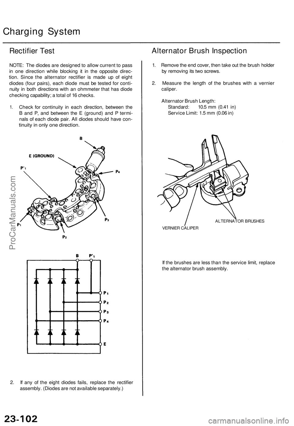
NOTE: The diodes are designed to allow current to pass
in one direction while blocking it in the opposite direc-
tion. Since the alternator rectifier is made up of eight
diodes (four pairs), each diode must be tested for conti-
nuity in both directions with an ohmmeter that has diode
checking capability; a total of 16 checks.
1.
Check for continuity in each direction, between the
B and P, and between the E (ground) and P termi-
nals of each diode pair. All diodes should have con-
tinuity in only one direction.
2. If any of the eight diodes fails, replace the rectifier
assembly. (Diodes are not available separately.)
Alternator Brush Inspection
1. Remove the end cover, then take out the brush holder
by removing its two screws.
2. Measure the length of the brushes with a vernier
caliper.
Alternator Brush Length:
Standard: 10.5 mm (0.41 in)
Service Limit: 1.5 mm (0.06 in)
ALTERNATOR BRUSHES
VERNIER CALIPER
If the brushes are less than the service limit, replace
the alternator brush assembly.ProCarManuals.com
Page 1594 of 1771
Gauge Assembl y
Removal
SRS component s ar e locate d in thi s area . Revie w th e SR S
componen t locations , precautions , an d procedure s i n th e
SR S (sectio n 24 ) befor e performin g repair s o r service .
1 . Remov e th e instrumen t pane l (se e sectio n 20 ).
2 . Remov e th e fou r screw s fro m th e gaug e assembly ,
and sprea d a protectiv e clot h o n th e uppe r colum n
cover.
PROTECTIV E CLOT H
3. Pr y th e gaug e assembl y out , an d disconnec t th e
connectors .
4. Carefull y remov e th e gaug e assembly .
5 . Instal l i n th e revers e orde r o f removal .
ProCarManuals.com
Page 1606 of 1771
Interlock Syste m
Componen t Locatio n Inde x
SRS component s ar e locate d in thi s area . Revie w th e SR S componen t locations , precautions , an d procedure s in th e SR S
(sectio n 24 ) befor e performin g repair s o r service .
A/T GEA R POSITIO N INDICATO R
Se e pag e 23-11 5
A/ T GEA R POSITIO N SWITC H
Test , pag e 23-14 6
INTERLOC KCONTROLUNITInpu t Test , pag e 23-13 0 KE
Y INTERLOC K SOLENOI D
an d KE Y INTERLOC K SWITC H
(I n th e steerin g loc k assembly )
Test , pag e 23-13 2
SHIF T LOC K SOLENOI D
Test , pag e 23-13 2
Replacement , pag e 23-13 3
PARKING PI N SWITC H
Test , pag e 23-13 4
Replacement , pag e 23-13 4
ProCarManuals.com
Page 1609 of 1771
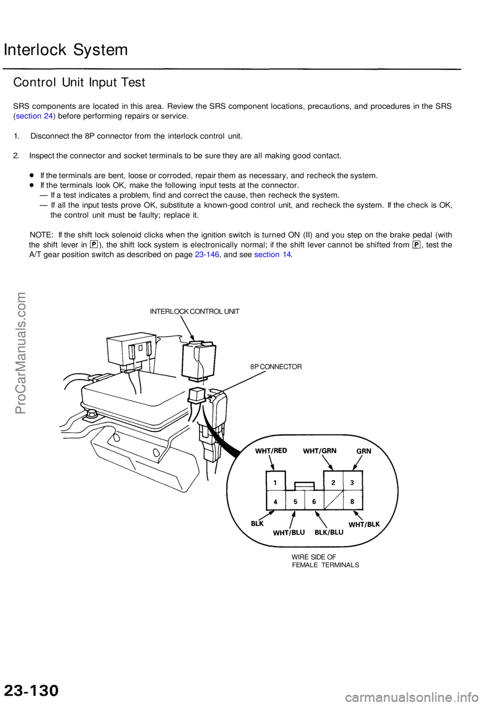
Interlock Syste m
Contro l Uni t Inpu t Tes t
SRS component s ar e locate d i n thi s area . Revie w th e SR S componen t locations , precautions , an d procedure s i n th e SR S
( sectio n 24 ) befor e performin g repair s o r service .
1 . Disconnec t th e 8 P connecto r fro m th e interloc k contro l unit .
2 . Inspec t th e connecto r an d socke t terminal s t o b e sur e the y ar e al l makin g goo d contact .
I f th e terminal s ar e bent , loos e o r corroded , repai r the m a s necessary , an d rechec k th e system .
I f th e terminal s loo k OK , mak e th e followin g inpu t test s a t th e connector .
— If a tes t indicate s a problem , fin d an d correc t th e cause , the n rechec k th e system .
— If al l th e inpu t test s prov e OK , substitut e a known-goo d contro l unit , an d rechec k th e system . I f th e chec k i s OK ,
th e contro l uni t mus t b e faulty ; replac e it .
NOTE : I f th e shif t loc k solenoi d click s whe n th e ignitio n switc h i s turne d O N (II ) an d yo u ste p o n th e brak e peda l (wit h
the shif t leve r i n ) , th e shif t loc k syste m is electronicall y normal ; i f th e shif t leve r canno t b e shifte d fro m , test th e
A/ T gea r positio n switc h a s describe d o n pag e 23-146 , an d se e sectio n 14 .
INTERLOC K CONTRO L UNI T
8P CONNECTO R
WIRE SID E O FFEMAL E TERMINAL S
ProCarManuals.com