Page 1614 of 1771
Safety Indicato r
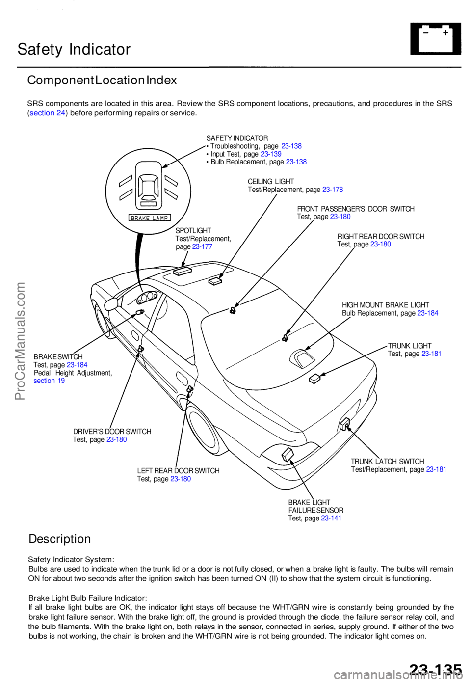
Componen t Locatio n Inde x
SRS component s ar e locate d in thi s area . Revie w th e SR S componen t locations , precautions , an d procedure s i n th e SR S
( sectio n 24 ) befor e performin g repair s o r service .
SAFETY INDICATO R
Troubleshooting , pag e 23-13 8
Inpu t Test , pag e 23-13 9
Bul b Replacement , pag e 23-13 8
CEILIN G LIGH T
Test/Replacement , pag e 23-17 8
FRON T PASSENGER' S DOO R SWITC H
Test , pag e 23-18 0
RIGH T REA R DOO R SWITC H
Test , pag e 23-18 0
BRAK E SWITC H
Test , pag e 23-18 4
Peda l Heigh t Adjustment ,
sectio n 1 9 HIG
H MOUN T BRAK E LIGH T
Bul b Replacement , pag e 23-18 4
TRUN K LIGH T
Test , pag e 23-18 1
DRIVER' S DOO R SWITC H
Test , pag e 23-18 0
LEFT REA R DOO R SWITC H
Test , pag e 23-18 0 TRUN
K LATC H SWITC H
Test/Replacement , pag e 23-18 1
BRAKE LIGH TFAILUR E SENSO R
Test , pag e 23-14 1
Descriptio n
Safety Indicato r System :
Bulb s ar e use d to indicat e whe n th e trun k li d o r a doo r i s no t full y closed , o r whe n a brak e ligh t i s faulty . Th e bulb s wil l remai n
O N fo r abou t tw o second s afte r th e ignitio n switc h ha s bee n turne d O N (II ) t o sho w tha t th e syste m circui t i s functioning .
Brak e Ligh t Bul b Failur e Indicator :
I f al l brak e ligh t bulb s ar e OK , th e indicato r ligh t stay s of f becaus e th e WHT/GR N wir e i s constantl y bein g grounde d b y th e
brak e ligh t failur e sensor . Wit h th e brak e ligh t off , th e ground is provide d throug h th e diode , th e failur e senso r rela y coil , an d
the bul b filaments . Wit h th e brak e ligh t on , bot h relay s in th e sensor , connecte d in series , suppl y ground . I f eithe r o f th e tw o
bulb s is no t working , th e chai n is broke n an d th e WHT/GR N wir e is no t bein g grounded . Th e indicato r ligh t come s on .
SPOTLIGH T
Test/Replacement ,
pag e 23-17 7
ProCarManuals.com
Page 1616 of 1771
Indicator Inpu t Tes t
SRS component s ar e locate d i n thi s area . Revie w th e SR S componen t locations , precautions , an d procedure s i n th e SR S
( sectio n 24 ) befor e performin g repair s o r service .
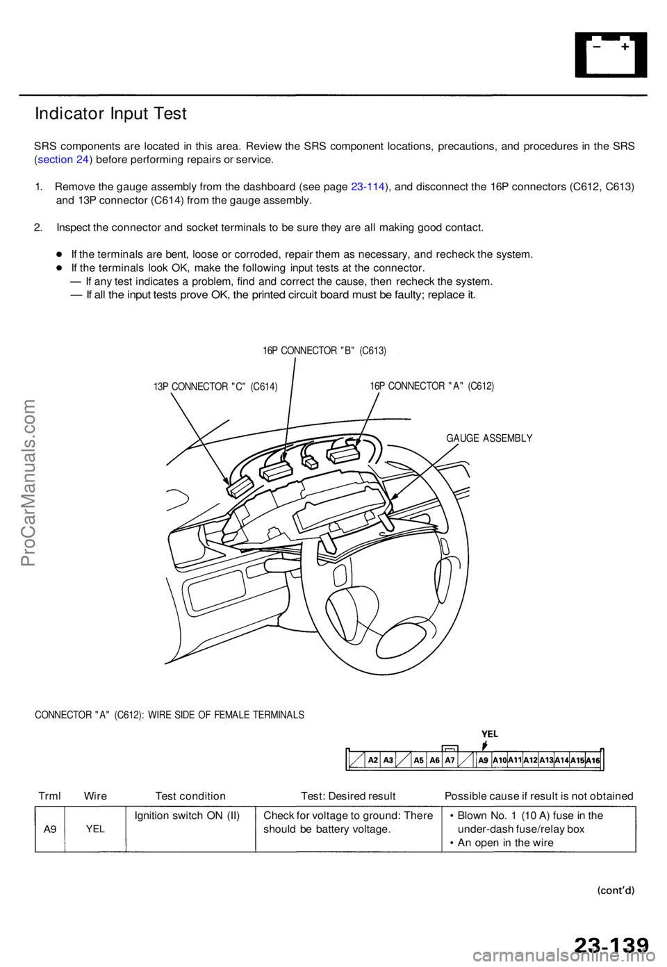
1 . Remov e th e gaug e assembl y fro m th e dashboar d (se e pag e 23-114 ), an d disconnec t th e 16 P connector s (C612 , C613 )
an d 13 P connecto r (C614 ) fro m th e gaug e assembly .
2 . Inspec t th e connecto r an d socke t terminal s t o b e sur e the y ar e al l makin g goo d contact .
I f th e terminal s ar e bent , loos e o r corroded , repai r the m a s necessary , an d rechec k th e system .
I f th e terminal s loo k OK , mak e th e followin g inpu t test s a t th e connector .
— If an y tes t indicate s a problem , fin d an d correc t th e cause , the n rechec k th e system .
— If al l th e inpu t test s prov e OK , th e printe d circui t boar d mus t b e faulty ; replac e it .
16 P CONNECTO R "B " (C613 )
13 P CONNECTO R "C " (C614 ) 16
P CONNECTO R "A " (C612 )
GAUG E ASSEMBL Y
CONNECTO R "A " (C612) : WIR E SID E O F FEMAL E TERMINAL S
Trml Wir e Test conditio n Test: Desire d resul t Possible caus e if resul t i s no t obtaine d
A9YE L
Ignitio n switc h O N (II ) Check fo r voltag e to ground : Ther e
shoul d b e batter y voltage . •
Blow n No . 1 (1 0 A ) fus e in th e
under-das h fuse/rela y bo x
• A n ope n i n th e wir e
ProCarManuals.com
Page 1619 of 1771
A/T Gea r Positio n Indicato r
Componen t Locatio n Inde x
SRS component s ar e locate d i n thi s area . Revie w th e SR S componen t locations , precautions , an d procedure s i n th e SR S
( sectio n 24 ) befor e performin g repair s o r service .
A/T GEA R POSITIO N INDICATO R
Inpu t Test , pag e 23-14 4
Bul b Replacement , pag e 23-14 7
A/T GEA R POSITIO N SWITC H
Test , pag e 23-14 6
Replacement , sectio n 1 4
ProCarManuals.com
Page 1620 of 1771
A/T Gea r Positio n Indicato r
Indicator Inpu t Tes t
SRS component s ar e locate d in thi s area . Revie w th e SR S componen t locations , precautions , an d procedure s i n th e SR S
( sectio n 24 ) befor e performin g repair s o r service .
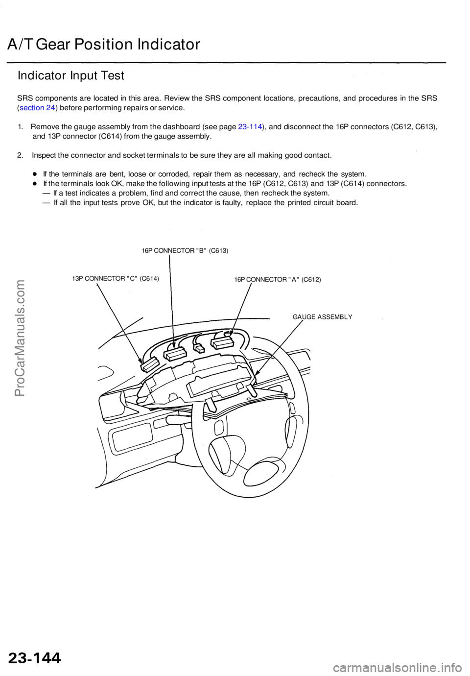
1 . Remov e th e gaug e assembl y fro m th e dashboar d (se e pag e 23-114 ), an d disconnec t th e 16 P connector s (C612 , C613) ,
an d 13 P connecto r (C614 ) fro m th e gaug e assembly .
2 . Inspec t th e connecto r an d socke t terminal s t o b e sur e the y ar e al l makin g goo d contact .
I f th e terminal s ar e bent , loos e o r corroded , repai r the m a s necessary , an d rechec k th e system .
I f th e terminal s loo k OK , mak e th e followin g inpu t test s a t th e 16 P (C612 , C613 ) an d 13 P (C614 ) connectors .
— If a tes t indicate s a problem , fin d an d correc t th e cause , the n rechec k th e system .
— If al l th e inpu t test s prov e OK , bu t th e indicato r i s faulty , replac e th e printe d circui t board .
16P CONNECTO R "B " (C613 )
13 P CONNECTO R "C " (C614 )
16P CONNECTO R "A " (C612 )
GAUG E ASSEMBL Y
ProCarManuals.com
Page 1624 of 1771
Integrated Contro l Uni t
Inpu t Tes t
SRS component s ar e locate d i n thi s area . Revie w th e SR S componen t locations , precautions , an d procedure s i n th e SR S
( sectio n 24 ) befor e performin g repair s o r service .
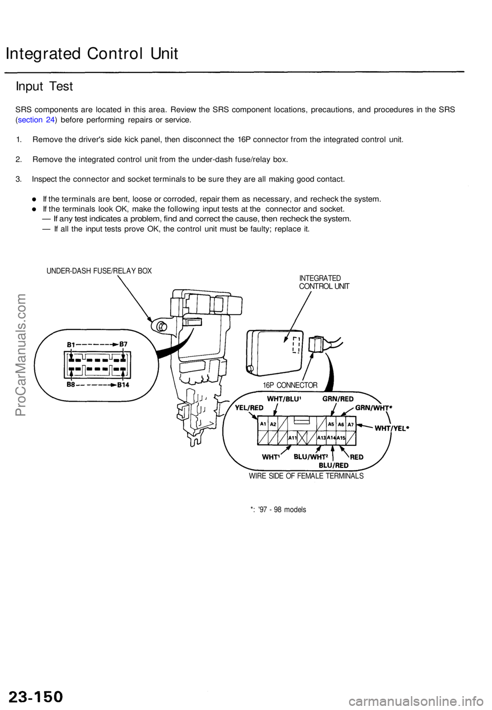
1 . Remov e th e driver' s sid e kic k panel , the n disconnec t th e 16 P connecto r fro m th e integrate d contro l unit .
2 . Remov e th e integrate d contro l uni t fro m th e under-das h fuse/rela y box .
3 . Inspec t th e connecto r an d socke t terminal s t o b e sur e the y ar e al l makin g goo d contact .
I f th e terminal s ar e bent , loos e o r corroded , repai r the m a s necessary , an d rechec k th e system .
I f th e terminal s loo k OK , mak e th e followin g inpu t test s a t th e connecto r an d socket .
— If an y tes t indicate s a problem , fin d an d correc t th e cause , the n rechec k th e system .
— If al l th e inpu t test s prov e OK , th e contro l uni t mus t b e faulty ; replac e it .
UNDER-DAS H FUSE/RELA Y BO X
INTEGRATED
CONTROL UNI T
16P CONNECTO R
WIR E SID E O F FEMAL E TERMINAL S
* : '9 7 - 9 8 model s
ProCarManuals.com
Page 1628 of 1771
Key-in Reminde r Syste m
Entry Ligh t Time r Syste m
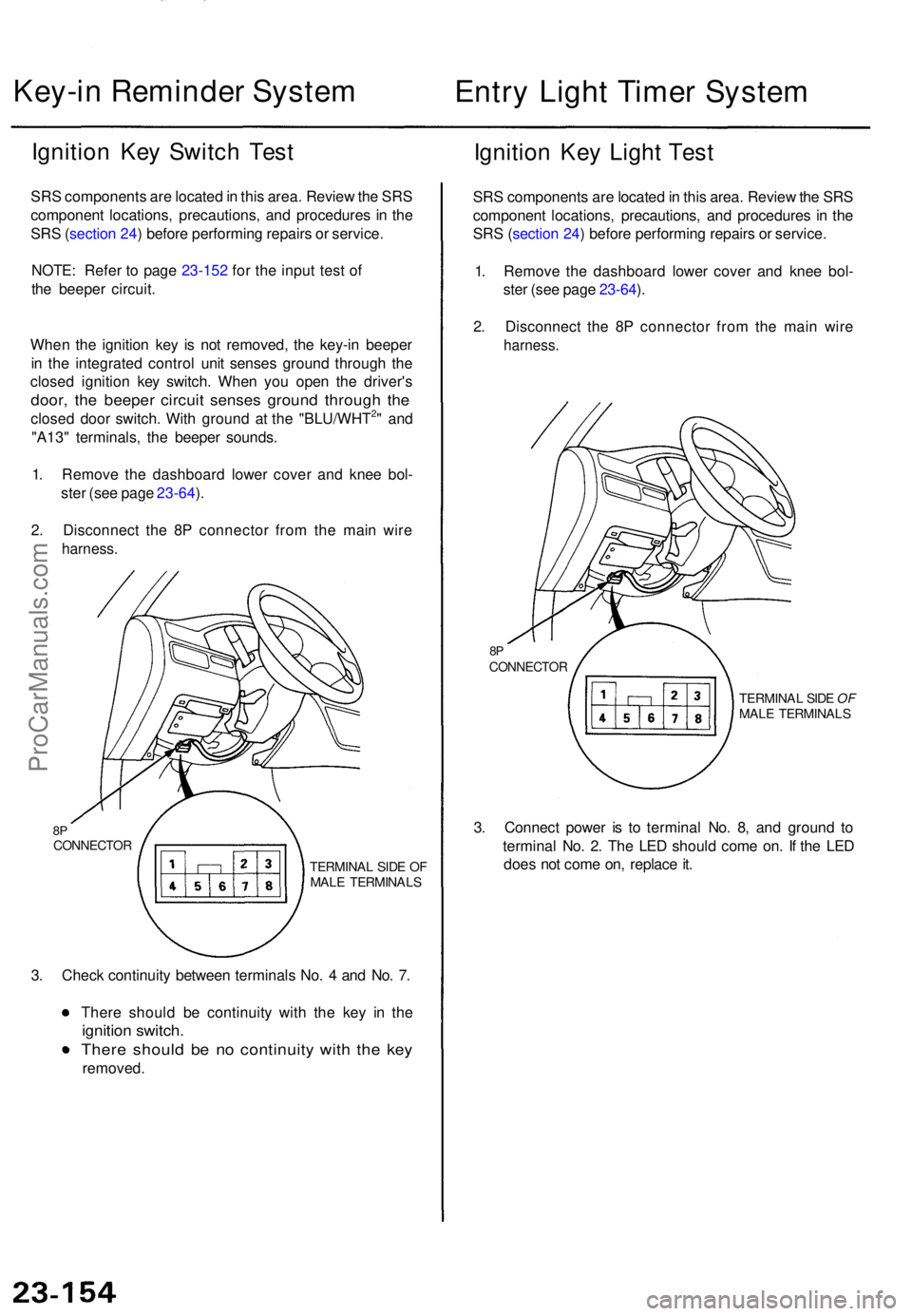
Ignition Ke y Switc h Tes t
SRS component s ar e locate d in thi s area . Revie w th e SR S
componen t locations , precautions , an d procedure s i n th e
SR S (sectio n 24 ) befor e performin g repair s o r service .
NOTE : Refe r t o pag e 23-152 for the input test of
the beepe r circuit.
Whe n th e ignitio n ke y i s no t removed , th e key-i n beepe r
i n th e integrate d contro l uni t sense s groun d throug h th e
close d ignitio n ke y switch . Whe n yo u ope n th e driver' s
door, th e beepe r circui t sense s groun d throug h th e
close d doo r switch . Wit h groun d a t th e "BLU/WHT2" an d
"A13 " terminals , th e beepe r sounds .
1 . Remov e th e dashboar d lowe r cove r an d kne e bol -
ste r (se e pag e 23-64 ).
2 . Disconnec t th e 8 P connecto r fro m th e mai n wir e
harness .
8PCONNECTO R
TERMINAL SID E O F
MAL E TERMINAL S
3. Chec k continuit y betwee n terminal s No . 4 an d No . 7 .
Ther e shoul d b e continuit y wit h th e ke y i n th e
ignitio n switch .
There shoul d b e n o continuit y wit h th e ke y
removed .
Ignition Ke y Ligh t Tes t
SRS component s ar e locate d in thi s area . Revie w th e SR S
componen t locations , precautions , an d procedure s i n th e
SR S (sectio n 24 ) befor e performin g repair s o r service .
1 . Remov e th e dashboar d lowe r cove r an d kne e bol -
ste r (se e pag e 23-64 ).
2 . Disconnec t th e 8 P connecto r fro m th e mai n wir e
harness .
8PCONNECTO R
TERMINAL SID E OF
MAL E TERMINAL S
3. Connec t powe r i s t o termina l No . 8 , an d groun d t o
termina l No . 2 . Th e LE D shoul d com e on . I f th e LE D
doe s no t com e on , replac e it .
ProCarManuals.com
Page 1632 of 1771
Lighting Syste m
Combinatio n Ligh t Switc h Tes t
SRS component s ar e locate d in thi s area . Revie w th e SR S componen t locations , precautions , an d procedure s i n th e SR S
( sectio n 24 ) befor e performin g repair s o r service .
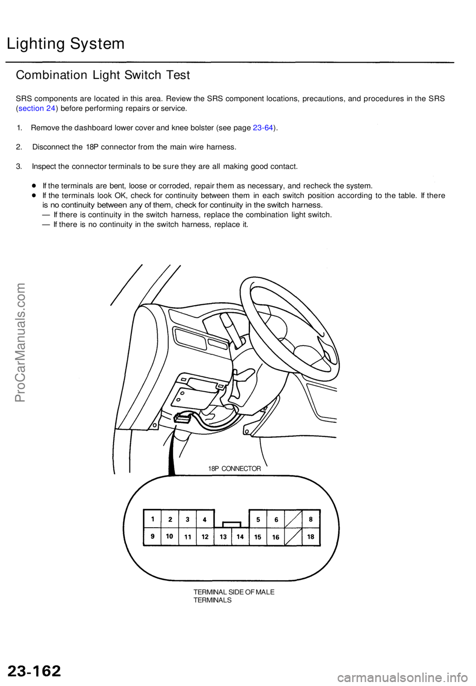
1 . Remov e th e dashboar d lowe r cove r an d kne e bolste r (se e pag e 23-64 ).
2 . Disconnec t th e 18 P connecto r fro m th e mai n wir e harness .
3 . Inspec t th e connecto r terminal s t o b e sur e the y ar e al l makin g goo d contact .
I f th e terminal s ar e bent , loos e o r corroded , repai r the m a s necessary , an d rechec k th e system .
I f th e terminal s loo k OK , chec k fo r continuit y betwee n the m in eac h switc h positio n accordin g t o th e table . I f ther e
is n o continuit y betwee n an y o f them , chec k fo r continuit y in th e switc h harness .
— If ther e i s continuit y i n th e switc h harness , replac e th e combinatio n ligh t switch .
— If ther e i s n o continuit y i n th e switc h harness , replac e it .
18 P CONNECTO R
TERMINAL SID E O F MAL ETERMINAL S
ProCarManuals.com
Page 1634 of 1771
Lighting Syste m
Daytim e Runnin g Light s Contro l Uni t Inpu t Tes t (Canada )
SRS component s ar e locate d i n thi s area . Revie w th e SR S componen t locations , precautions , an d procedure s i n th e SR S
(sectio n 24 ) befor e performin g repair s o r service .
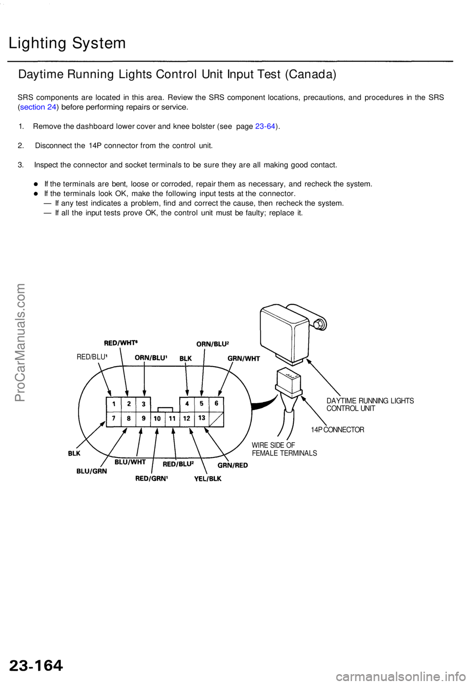
1. Remov e th e dashboar d lowe r cove r an d kne e bolste r (se e pag e 23-64 ).
2 . Disconnec t th e 14 P connecto r fro m th e contro l unit .
3 . Inspec t th e connecto r an d socke t terminal s t o b e sur e the y ar e al l makin g goo d contact .
I f th e terminal s ar e bent , loos e o r corroded , repai r the m a s necessary , an d rechec k th e system .
I f th e terminal s loo k OK , mak e th e followin g inpu t test s a t th e connector .
— If an y tes t indicate s a problem , fin d an d correc t th e cause , the n rechec k th e system .
— If al l th e inpu t test s prov e OK , th e contro l uni t mus t b e faulty ; replac e it .
RED/BL U
DAYTIM E RUNNIN G LIGHT SCONTRO L UNI T
14P CONNECTO R
WIRE SID E O FFEMAL E TERMINAL S
ProCarManuals.com