1995 ACURA TL service
[x] Cancel search: servicePage 1719 of 1771
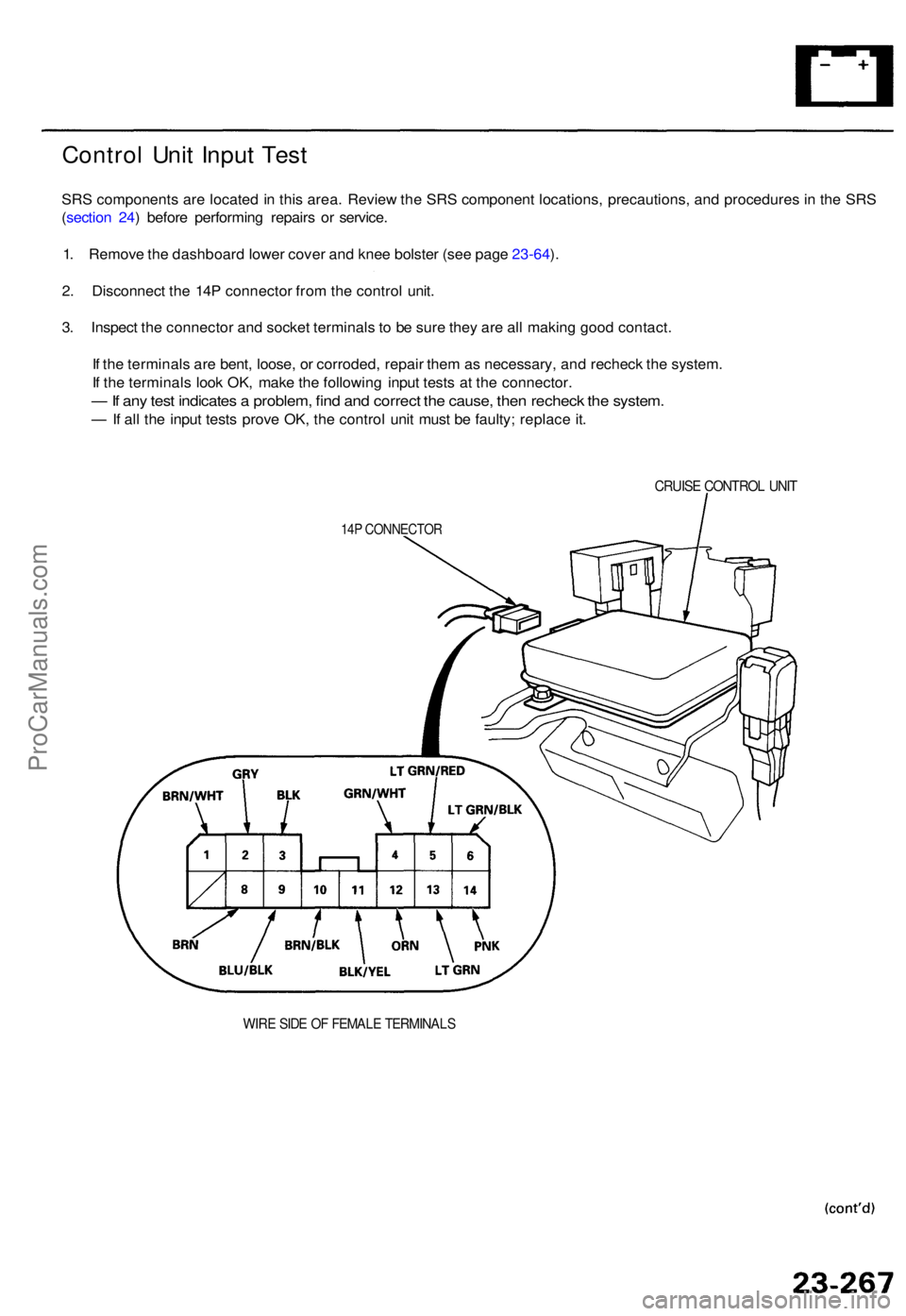
Control Uni t Inpu t Tes t
SRS component s ar e locate d in thi s area . Revie w th e SR S componen t locations , precautions , an d procedure s i n th e SR S
( sectio n 24 ) befor e performin g repair s o r service .
1 . Remov e th e dashboar d lowe r cove r an d kne e bolste r (se e pag e 23-64 ).
2 . Disconnec t th e 14 P connecto r fro m th e contro l unit .
3 . Inspec t th e connecto r an d socke t terminal s t o b e sur e the y ar e al l makin g goo d contact .
I f th e terminal s ar e bent , loose , o r corroded , repai r the m a s necessary , an d rechec k th e system .
I f th e terminal s loo k OK , mak e th e followin g inpu t test s a t th e connector .
— If an y tes t indicate s a problem , fin d an d correc t th e cause , the n rechec k th e system .
— If al l th e inpu t test s prov e OK , th e contro l uni t mus t b e faulty ; replac e it .
CRUIS E CONTRO L UNI T
14P CONNECTO R
WIRE SID E O F FEMAL E TERMINAL S
ProCarManuals.com
Page 1721 of 1771
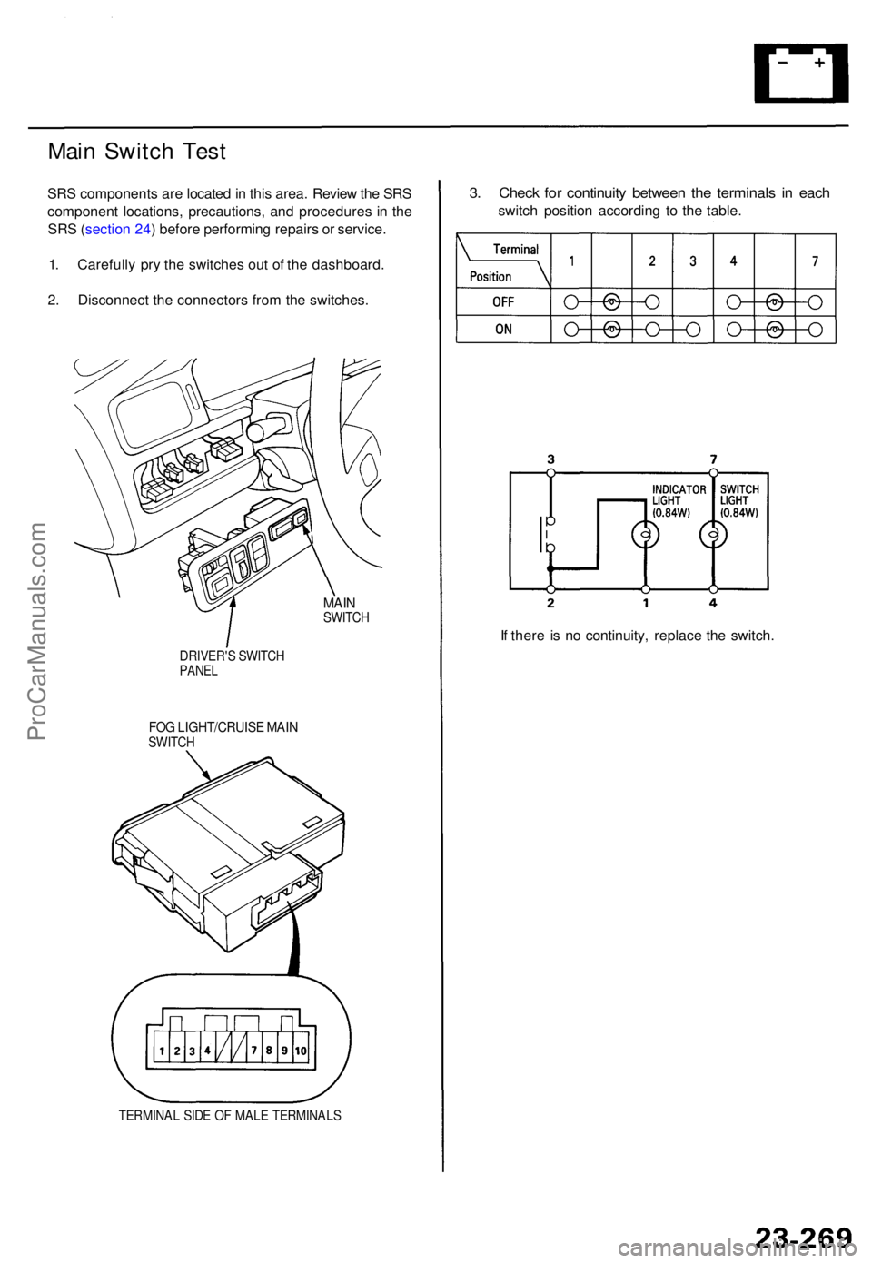
Main Switc h Tes t
SRS component s ar e locate d in thi s area . Revie w th e SR S
componen t locations , precautions , an d procedure s i n th e
SR S (sectio n 24 ) befor e performin g repair s o r service .
1 . Carefull y pr y th e switche s ou t o f th e dashboard .
2 . Disconnec t th e connector s fro m th e switches .
MAINSWITC H
DRIVER' S SWITC H
PANEL
FOG LIGHT/CRUIS E MAI NSWITC H
TERMINA L SID E O F MAL E TERMINAL S
3. Chec k fo r continuit y betwee n th e terminal s i n eac h
switc h positio n accordin g t o th e table .
I f ther e i s n o continuity , replac e th e switch .
ProCarManuals.com
Page 1722 of 1771
Cruise Contro l
Set/Resum e Switc h Test/Replacemen t
SRS component s ar e locate d in thi s area . Revie w th e SR S
componen t locations , precautions , an d procedure s i n th e
SR S (sectio n 24 ) befor e performin g repair s o r service .
1 . Mak e sur e yo u hav e th e anti-thef t cod e fo r th e radio ,
the n writ e dow n th e frequencie s fo r th e radio' s pre -
se t buttons .
2 . Disconnec t th e batter y negativ e cable , the n discon -
nec t th e positiv e cable , an d wai t a t leas t thre e min -
utes .
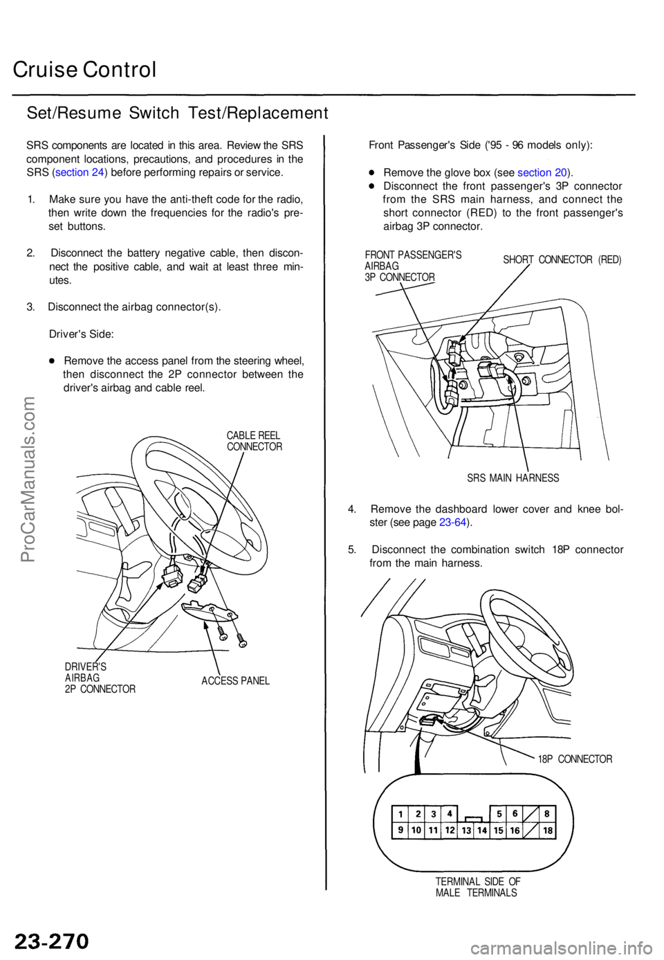
3 . Disconnec t th e airba g connector(s) .
Driver' s Side :
Remov e th e acces s pane l fro m th e steerin g wheel ,
the n disconnec t th e 2 P connecto r betwee n th e
driver' s airba g an d cabl e reel .
CABL E REE L
CONNECTO R
DRIVER' S
AIRBAG2P CONNECTO R ACCES
S PANE L
Front Passenger' s Sid e ('9 5 - 9 6 model s only) :
Remov e th e glov e bo x (se e sectio n 20 ).
Disconnec t th e fron t passenger' s 3 P connecto r
fro m th e SR S mai n harness , an d connec t th e
shor t connecto r (RED ) t o th e fron t passenger' s
airba g 3 P connector .
FRONT PASSENGER' S
AIRBA G
3 P CONNECTO R SHOR
T CONNECTO R (RED )
SR S MAI N HARNES S
4. Remov e th e dashboar d lowe r cove r an d kne e bol -
ste r (se e pag e 23-64 ).
5 . Disconnec t th e combinatio n switc h 18 P connecto r
fro m th e mai n harness .
18P CONNECTO R
TERMINA L SID E O F
MAL E TERMINAL S
ProCarManuals.com
Page 1731 of 1771
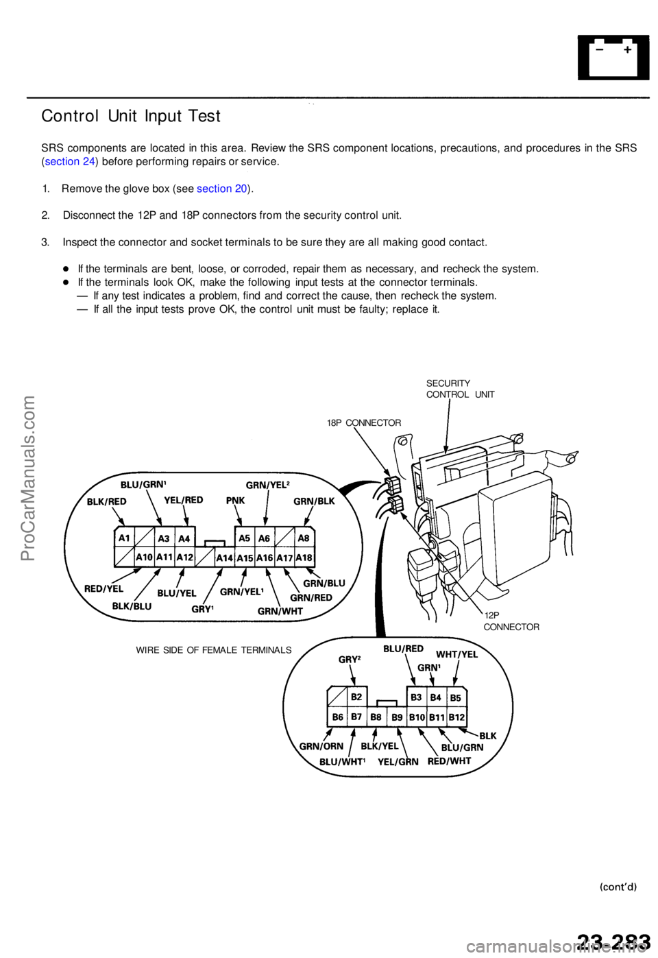
Control Uni t Inpu t Tes t
SRS component s ar e locate d in thi s area . Revie w th e SR S componen t locations , precautions , an d procedure s i n th e SR S
( sectio n 24 ) befor e performin g repair s o r service .
1 . Remov e th e glov e bo x (se e sectio n 20 ).
2 . Disconnec t th e 12 P an d 18 P connector s fro m th e securit y contro l unit .
3 . Inspec t th e connecto r an d socke t terminal s t o b e sur e the y ar e al l makin g goo d contact .
I f th e terminal s ar e bent , loose , o r corroded , repai r the m a s necessary , an d rechec k th e system .
I f th e terminal s loo k OK , mak e th e followin g inpu t test s a t th e connecto r terminals .
— If an y tes t indicate s a problem , fin d an d correc t th e cause , the n rechec k th e system .
— If al l th e inpu t test s prov e OK , th e contro l uni t mus t b e faulty ; replac e it .
SECURIT YCONTROL UNI T
18 P CONNECTO R
WIR E SID E O F FEMAL E TERMINAL S
12PCONNECTO R
ProCarManuals.com
Page 1738 of 1771
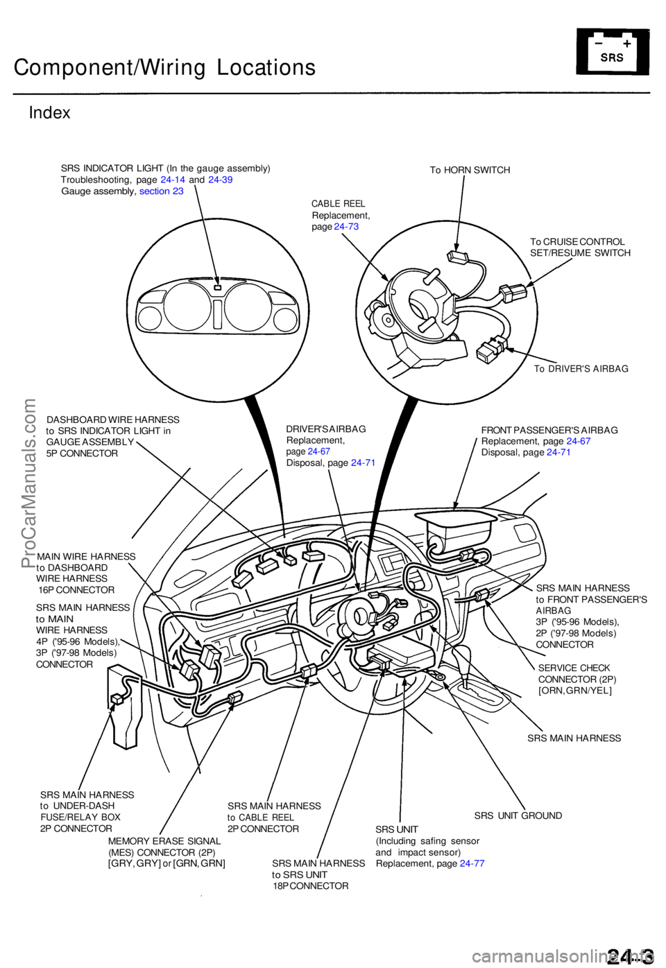
Component/Wiring Location s
Index
SRS INDICATO R LIGH T (I n th e gaug e assembly )
Troubleshooting , pag e 24-1 4 an d 24-3 9
Gaug e assembly , sectio n 2 3
To HOR N SWITC H
DASHBOAR D WIR E HARNES S
t o SR S INDICATO R LIGH T in
GAUG E ASSEMBL Y
5 P CONNECTO R
To DRIVER' S AIRBA G
FRONT PASSENGER' S AIRBA G
Replacement , pag e 24-6 7
Disposal , pag e 24-7 1
T
o CRUIS E CONTRO L
SET/RESUM E SWITC H
MAI N WIR E HARNES S
t o DASHBOAR D
WIR E HARNES S
16 P CONNECTO R
SR S MAI N HARNES S
to MAI NWIRE HARNES S
4 P ('95-9 6 Models) ,
3 P ('97-9 8 Models )
CONNECTO R SR
S MAI N HARNES S
t o FRON T PASSENGER' S
AIRBAG3P ('95-9 6 Models) ,
2 P ('97-9 8 Models )
CONNECTO R
SERVICE CHEC KCONNECTO R (2P )
[ORN , GRN/YEL ]
SR S MAI N HARNES S
SR S MAI N HARNES S
t o UNDER-DAS H
FUSE/RELAY BO X2P CONNECTO R
MEMOR Y ERAS E SIGNA L
(MES ) CONNECTO R (2P )
[GRY , GRY ] or [GRN , GRN ]SRS MAI N HARNES Sto SR S UNI T18P CONNECTO R SR
S UNI T GROUN D
SRS UNI T(Includin g safin g senso r
an d impac t sensor )
Replacement , pag e 24-7 7
CABL E REE LReplacement ,
pag e 24-7 3
DRIVER' S AIRBA G
Replacement ,
page 24-67Disposal , pag e 24-7 1
SR S MAI N HARNES S
to CABL E REE L2P CONNECTO R
ProCarManuals.com
Page 1739 of 1771
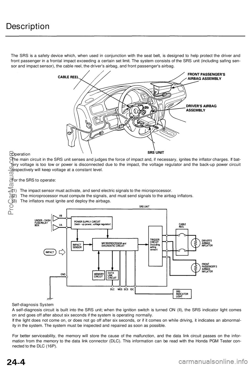
Description
The SR S is a safet y devic e which , whe n use d i n conjunctio n wit h th e sea t belt , i s designe d t o hel p protec t th e drive r an d
fron t passenge r i n a fronta l impac t exceedin g a certai n se t limit . Th e syste m consist s o f th e SR S uni t (includin g safin g sen -
so r an d impac t sensor) , th e cabl e reel , th e driver' s airbag , an d fron t passenger' s airbag .
Operatio n
Th e mai n circui t i n th e SR S uni t sense s an d judge s th e forc e o f impac t and , i f necessary , ignite s th e inflato r charges . I f bat -
ter y voltag e i s to o lo w o r powe r i s disconnecte d du e t o th e impact , th e voltag e regulato r an d th e back-u p powe r circui t
respectivel y wil l kee p voltag e a t a constan t level .
Fo r th e SR S to operate :
(1 ) Th e impac t senso r mus t activate , an d sen d electri c signal s t o th e microprocessor .
(2 ) Th e microprocesso r mus t comput e th e signals , an d mus t sen d signal s t o th e airba g inflators .
(3 ) Th e inflator s mus t ignit e an d deplo y th e airbags .
Self-diagnosi s Syste m
A self-diagnosi s circui t i s buil t int o th e SR S unit ; whe n th e ignitio n switc h i s turne d O N (II) , th e SR S indicato r ligh t come s
o n an d goe s of f afte r abou t si x second s if th e syste m is operatin g normally .
I f th e ligh t doe s no t com e on , o r doe s no t g o of f afte r si x seconds , o r i f i t come s o n whil e driving , i t indicate s a n abnormal -
it y i n th e system . Th e syste m mus t b e inspecte d an d repaire d a s soo n a s possible .
Fo r bette r serviceability , th e memor y wil l stor e th e caus e o f th e malfunction , an d th e dat a lin k circui t passe s o n th e infor -
matio n fro m th e memor y t o th e dat a lin k connecto r (DLC) . Thi s informatio n ca n b e rea d wit h th e Hond a PG M Teste r con -
necte d to th e DL C (16P) .
ProCarManuals.com
Page 1740 of 1771
Precautions/Procedures
General Precaution s
• Carefull y inspec t an y SR S par t befor e yo u instal l it . D o
not instal l an y par t tha t show s sign s o f bein g droppe d
or improperl y handled , suc h a s dents , crack s o r defor -
mation :
Airbag assemblie s
Cabl e ree l
SRS uni t
• Us e onl y a digita l multimete r t o chec k th e system . I f
it' s no t a Hond a multimeter , mak e sur e it s outpu t i s
1 0 m A (0.0 1 A ) o r les s whe n switche d t o th e smalles t
valu e i n th e ohmmete r range . A teste r wit h a highe r
outpu t coul d damag e th e airba g circui t o r caus e acci -
denta l deploymen t an d possibl e injury .
• D o no t instal l use d SR S part s fro m anothe r vehicle .
Whe n makin g SR S repairs , us e onl y ne w parts .
• Excep t whe n performin g electrica l inspections ,
alway s disconnec t bot h th e negativ e cabl e an d posi -
tiv e cabl e fro m th e battery , an d wai t a t leas t thre e
minute s befor e beginnin g work .
• Replacemen t of the combinatio n ligh t an d wiper /
washer switche s an d cruis e contro l switc h ca n b e
don e withou t removin g th e steerin g wheel :
Fo r combinatio n ligh t an d wiper/washe r switc h
replacement , se e sectio n 23 .
Fo r cruis e contro l set/resume/cance l switc h
replacement , se e sectio n 23 .
• Wheneve r th e ignitio n switc h i s O N (II) , o r ha s bee n
turne d OF F fo r les s tha n thre e minutes , b e carefu l no t
t o bum p th e SR S unit ; th e airbag s coul d accidentall y
deplo y an d caus e damag e o r injury .
• Wheneve r th e airba g ha s bee n activated , replac e th e
SR S unit .
• Th e origina l radi o ha s a code d thef t protectio n circuit .
B e sur e to ge t th e customer' s cod e numbe r befor e dis -
connectin g th e batter y cables .
Airbag Handlin g an d Storag e
Do no t tr y t o disassembl e th e airba g assembly . I t ha s n o
serviceabl e parts . Onc e a n airba g ha s bee n operate d
(deployed) , i t canno t b e repaire d o r reused .
Fo r temporar y storag e o f th e airba g assembl y durin g ser -
vice , pleas e observ e th e followin g precautions :
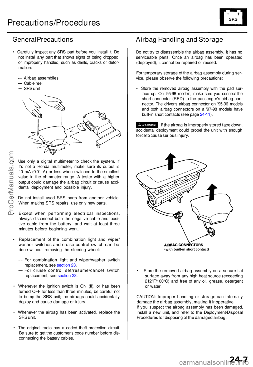
• Stor e th e remove d airba g assembl y wit h th e pa d sur -
fac e up . O n '95-9 6 models , mak e sur e yo u connec t th e
shor t connecto r (RED ) t o th e passenger' s airba g con -
nector . Th e driver' s airba g connecto r o n '95-9 6 model s
an d bot h airba g connector s o n a '97-9 8 model s hav e
built-i n shor t contact s (se e pag e 24-11 ).
I f th e airba g is improperl y store d fac e down ,
accidenta l deploymen t coul d prope l th e uni t wit h enoug h
forc e to caus e seriou s injury .
• Stor e th e remove d airba g assembl y o n a secur e fla t
surfac e awa y fro m an y hig h hea t sourc e (exceedin g
212°F/100°C ) an d fre e o f an y oil , grease , detergen t
o r water .
CAUTION : Imprope r handlin g o r storag e ca n internall y
damag e th e airba g assembly , makin g it inoperative .
I f yo u suspec t th e airba g assembl y ha s bee n damaged ,
instal l a ne w unit , an d refe r t o th e Deployment/Disposa l
Procedure s fo r disposin g o f th e damage d airbag .
ProCarManuals.com
Page 1764 of 1771
Airbag
Disposa l (cont'd )
7. Connec t a 1 2 vol t batter y t o th e tool :
• I f th e gree n ligh t o n th e too l come s on , th e air -
ba g ignite r circui t i s defectiv e an d canno t deplo y
th e airbag . G o t o Damage d Airba g Specia l
Procedure .
• I f th e re d ligh t o n th e too l come s on , th e airba g i s
read y t o b e deployed .
8 . Pus h th e tool' s deploymen t switch . Th e airba g
shoul d deplo y (deploymen t i s bot h highl y audibl e
an d visibl e a lou d nois e an d rapi d inflatio n o f th e
bag , followe d b y slo w deflation) .
• I f audible/visibl e deploymen t happens , an d th e
gree n ligh t o n th e too l come s on , continu e wit h
this procedure .
• I f th e airba g doesn' t deploy , ye t th e gree n ligh t
come s ON , it s ignite r i s defective . G o t o Dam -
age d Airba g Specia l Procedure .
• Durin g deployment , th e airba g ca n becom e ho t
enoug h t o bur n you . Wai t thirt y minute s afte r
deploymen t befor e touchin g th e airbag .
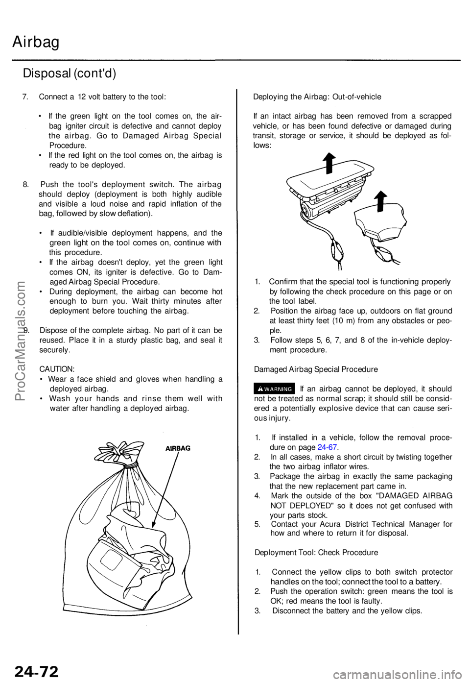
9 . Dispos e o f th e complet e airbag . N o par t o f i t ca n b e
reused . Plac e i t i n a sturd y plasti c bag , an d sea l i t
securely .
CAUTION :
• Wea r a fac e shiel d an d glove s whe n handlin g a
deploye d airbag .
• Was h you r hand s an d rins e the m wel l wit h
wate r afte r handlin g a deploye d airbag . Deployin
g th e Airbag : Out-of-vehicl e
I f a n intac t airba g ha s bee n remove d fro m a scrappe d
vehicle , o r ha s bee n foun d defectiv e o r damage d durin g
transit , storag e o r service , i t shoul d b e deploye d a s fol -
lows :
1. Confir m tha t th e specia l too l i s functionin g properl y
by followin g th e chec k procedur e o n thi s pag e o r o n
th e too l label .
2 . Positio n th e airba g fac e up , outdoor s o n fla t groun d
a t leas t thirt y fee t (1 0 m ) fro m an y obstacle s o r peo -
ple.
3. Follo w step s 5 , 6 , 7 , an d 8 of th e in-vehicl e deploy -
men t procedure .
Damage d Airba g Specia l Procedur e
I f a n airba g canno t b e deployed , i t shoul d
no t b e treate d a s norma l scrap ; i t shoul d stil l b e consid -
ere d a potentiall y explosiv e devic e tha t ca n caus e seri -
ou s injury .
1 . I f installe d i n a vehicle , follo w th e remova l proce -
dur e o n pag e 24-67 .
2 . I n al l cases , mak e a shor t circui t b y twistin g togethe r
th e tw o airba g inflato r wires .
3 . Packag e th e airba g i n exactl y th e sam e packagin g
tha t th e ne w replacemen t par t cam e in .
4 . Mar k th e outsid e o f th e bo x "DAMAGE D AIRBA G
NO T DEPLOYED " s o i t doe s no t ge t confuse d wit h
you r part s stock .
5 . Contac t you r Acur a Distric t Technica l Manage r fo r
ho w an d wher e t o retur n i t fo r disposal .
Deploymen t Tool : Chec k Procedur e
1 . Connec t th e yello w clip s t o bot h switc h protecto r
handles o n th e tool ; connec t th e too l t o a battery .
2. Pus h th e operatio n switch : gree n mean s th e too l i s
OK ; re d mean s th e too l i s faulty .
3 . Disconnec t th e batter y an d th e yello w clips .
ProCarManuals.com