Page 10 of 1771
Lift and Support Points
FRONT SUPPORT POINT
REAR SUPPORT POINT
LIFT BLOCKS
Lift and Safety Stands
1. Place the lift blocks as shown.
2. Raise the hoist a few inches (centimeters), and rock the vehicle to be sure it is firmly supported.
3. Raise the hoist to full height, and inspect the lift points for solid support.
NOTE: Use the same support points to support the vehicle on safety stands.ProCarManuals.com
Page 11 of 1771
Floor Jack
1. Set the parking brake, and block the wheels that are
not being lifted.
2. When lifting the rear of the vehicle, put the shift
lever in position.
3. Raise the vehicle high enough to insert the safety
stands.
4. Adjust and place the safety stands so the vehicle
will be approximately level, then lower the vehicle
onto them.
Always use safety stands when working on or under
any vehicle that is supported by only a jack.
Never attempt to use a bumper jack for lifting or
supporting the vehicle.
Front
Center the jack
bracket in the middle
of the jack lift platform.
JACK LIFT PLATFORM
Rear
Center the jack
bracket in the middle
of the jack lift platform.
JACK LIFT PLATFORMProCarManuals.com
Page 28 of 1771

Lubrication Points
For the details of lubrication points and types of lubricants to be applied, refer to the illustrated index and various work
procedures (such as Assembly/Reassembly, Replacement, Overhaul, Installation, etc.) contained in each section.
No.
1
2
3
4
5
6
7
8
9
10
11
12
13
14
15
16
17
18
19
20
21
LUBRICATION POINTS
Engine
Transmission
Brake Line (Includes Anti-lock brake line)
Power steering gearbox
Steering boots
Throttle cable end
Steering ball joints
Shift lever (Automatic transmission)
Pedal linkage
Intermediate shaft
Brake master cylinder pushrod
Fuel
fill
lid
Trunk hinges
Door hinges upper and lower
Door opening detents
Hood hinges and hood latch
Brake pipe joint (Front and rear wheel house)
Caliper Piston seal, Dust seal,
Caliper pin, Piston
Power steering system
Differential
A/C compressor
LUBRICANT
API Service Grade: Use SH "Energy Conserving II" or SJ
"Energy Conserving" grade oil.
The oil container may also display the API Certification
mark shown below. Make sure it says "For Gasoline
Engines."
SAE Viscosity: See chart below.
Genuine Honda Premium Formula Automatic
Transmission Fluid (ATF)*1
Genuine Honda DOT3 Brake Fluid*2
Steering grease P/N 08733 - B070E
Multi-purpose grease
Honda White Lithium Grease
Rust preventives
Silicone grease
Genuine Honda Power Steering Fluid-V or S*3
Hypoid gear Oil API service GL4 or GL5
Viscosity:
at above -18°C (0°F): SAE 90
at less than -18°C (0°F): SAE 80 W-90
Compressor oil:
DENSO: ND-OIL8 (P/N 38897 - PR7 - A01 AH or 38899 -
PR7-A01)
(For Refrigerant: HFC-134a (R-134a))
API SERVICE LABEL
API CERTIFICATION MARK
Recommended Engine Oil
Engine oil viscosity for ambient temperature ranges
NOTE: The following information as marked *1, *2 and *3 on above chart details for 1997 model:
*1: Always use Genuine Honda Premium Formula Automatic Transmission Fluid (ATF). Using a non-Honda ATF can affect
shift quality.
*2: Always use Genuine Honda DOT3 Brake Fluid. Using a non-Honda brake fluid can cause corrosion and decrease the
life of the system.
*3: Always use Genuine Honda Power Steering Fluid-V or S. Using any other type of power steering fluid or automatic
transmission fluid can cause increase wear and poor steering in cold weather.ProCarManuals.com
Page 44 of 1771

Engine Removal/Installatio n
Removal (cont'd )
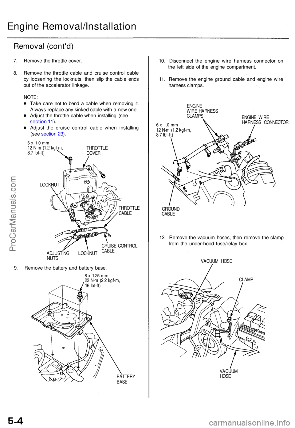
7. Remov e th e throttl e cover .
8.Remov e th e throttl e cabl e an d cruis e contro l cabl e
b y loosenin g th e locknuts , the n sli p th e cabl e end s
ou t o f th e accelerato r linkage .
NOTE:
Take car e no t t o ben d a cabl e whe n removin g it .
Alway s replac e an y kinke d cabl e wit h a ne w one .
Adjus t th e throttl e cabl e whe n installin g (se e
sectio n 11 ).
Adjus t th e cruis e contro l cabl e whe n installin g
(se e sectio n 23 ).
6 x 1. 0 m m12 N- m (1. 2 kgf-m ,
8. 7 Ibf-ft ) THROTTL
ECOVER
LOCKNU T
THROTTLE
CABLE
ADJUSTIN G LOCKNU TNUTS
CRUIS E CONTRO LCABLE
9. Remov e th e batter y an d batter y base .
8 x 1.2 5 mm22 N- m (2. 2 kgf-m ,
1 6 Ibf-ft )
BATTER YBASE
10. Disconnec t th e engin e wir e harnes s connecto r o n
th e lef t sid e o f th e engin e compartment .
11 . Remov e th e engin e groun d cabl e an d engin e wir e
harnes s clamps .
ENGINEWIRE HARNES S
CLAMP S
6 x 1. 0 m m12 N- m (1. 2 kgf-m ,
8. 7 Ibf-ft ) ENGIN
E WIR E
HARNES S CONNECTO R
GROUN D
CABLE
12. Remov e th e vacuu m hoses , the n remov e th e clam p
fro m th e under-hoo d fuse/rela y box .
VACUU M HOS E
CLAM P
VACUU M
HOS E
ProCarManuals.com
Page 47 of 1771

25. Loosen the mounting bolt, lock bolt and adjusting
rod, then remove the alternator belt.
ADJUSTING
ROD
LOCK BOLT
8 x
1.25
mm
22 N-m (2.2 kgf-m,
16 Ibf-ft)
ALTERNATOR
BELT
MOUNTING BOLT
10 x
1.25
mm
44 N-m (4.5 kgf-m,
33 Ibf-ft)
26. Loosen the idler pulley center nut and adjusting bolt,
then remove the air conditioning (A/C) compressor
belt.
IDLER PULLEY
CENTER NUT
10 x
1.25
mm
44 N-m (4.5 kgf-m,
33 Ibf-ft)
ADJUSTING
BOLT
A/C COMPRESSOR
BELT
27. Disconnect the power steering pressure (PSP)
switch connector.
28. Remove the adjusting bolt, locknut and mounting
bolt, then remove the P/S pump belt and pump.
Do not disconnect the P/S hose.
ADJUSTING
BOLT
P/S PUMP
LOCKNUT
8 x
1.25
mm
22 N-m (2.2 kgf-m,
16 Ibf-ft)
PSP SWITCH
CONNECTOR
29.
P/S PUMP
BELT
MOUNTING BOLT
10 x
1.25
mm
44 N-m (4.5 kgf-m, 33 Ibf-ft)
Pull the carpet back to expose the secondary heated
oxygen sensor (Secondary HO2S) connector, then
disconnect the secondary HO2S connector.
SECONDARY
HO2S CONNECTORProCarManuals.com
Page 49 of 1771
41. Disconnect the vehicle speed sensor (VSS) connec-
tor, then remove the VSS/power steering speed
sensor.
Do not disconnect the fluid hoses.
6 x 1.0 mm
12 N-m (1.2 kgf-m,
8.7 Ibf-ft)
VSS CONNECTOR
VSS/POWER STEERING
SPEED SENSOR
42. Remove the heat shields from exhaust pipe A.
HEAT
SHIELDS
6 x 1.0 mm
12 N-m (1.2 kgf-m,
8.7 Ibf-ft)
43. Remove exhaust pipe A.
EXHAUST
PIPE A
GASKET
Replace.
SELF-LOCKING NUT
8 x
1.25
mm
22 N-m (2.2 kgf-m, 16 Ibf-ft)
Replace.
GASKETS
Replace.
GASKET
Replace.
TWC
6 x 1.0 mm
9.8 N-m (1.0 kgf-m,
7.2 Ibf-ft)
SELF-LOCKING NUT
8 x
1.25
mm
22 N-m (2.2 kgf-m,
16 Ibf-ft)
Replace.
SELF-LOCKING NUTS
10 x
1.25
mm
54 N-m (5.5 kgf-m,
40 Ibf-ft)
Replace.
44. Remove the wire harness cover and grommet, then
remove the three way catalytic converter (TWC).
SELF-LOCKING NUT
10 x
1.25
mm
32 N-m (3.3 kgf-m,
24 Ibf-ft)
Replace.
GROMMET
WIRE HARNESS
COVERProCarManuals.com
Page 50 of 1771

Engine Removal/Installatio n
Removal (cont'd )
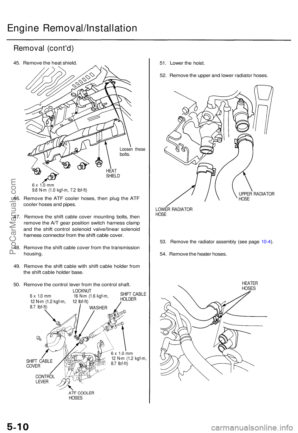
45. Remov e th e hea t shield .
Loosen thes ebolts.
HEAT
SHIEL D
6 x 1. 0 m m9.8 N- m (1. 0 kgf-m , 7. 2 Ibf-ft )
46. Remov e th e AT F coole r hoses , the n plu g th e AT F
coole r hose s an d pipes .
47 . Remov e th e shif t cabl e cove r mountin g bolts , the n
remov e th e A/ T gea r positio n switc h harnes s clam p
an d th e shif t contro l solenoi d valve/linea r solenoi d
harness connecto r fro m th e shif t cabl e cover .
48. Remov e th e shif t cabl e cove r fro m th e transmissio n
housing .
49 . Remov e th e shif t cabl e wit h shif t cabl e holde r fro m
th e shif t cabl e holde r base .
50 . Remov e th e contro l leve r fro m th e contro l shaft .
LOCKNU T
6 x 1. 0 m m 1 6 N- m (1. 6 kgf-m ,
12 N- m (1. 2 kgf-m , 1 2 Ibf-ft )8.7 Ibf-ft ) SHIF
T CABL E
HOLDE R
SHIF T CABL E
COVE R
CONTRO L
LEVER
6 x 1. 0 m m12 N- m (1. 2 kgf-m ,
8. 7 Ibf-ft )
ATF COOLE RHOSES
51. Lowe r th e hoist .
52 . Remov e th e uppe r an d lowe r radiato r hoses .
UPPER RADIATO R
HOS E
LOWE R RADIATO R
HOS E
53. Remov e th e radiato r assembl y (se e pag e 10-4 ).
54 . Remov e th e heate r hoses .
HEATE RHOSES
WASHE R
ProCarManuals.com
Page 62 of 1771

InspectionTension Adjustmen t
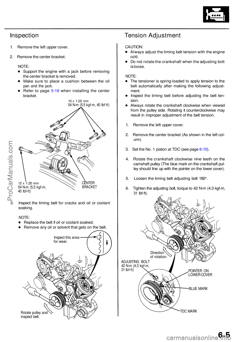
1. Remov e th e lef t uppe r cover .
2 . Remov e th e cente r bracket .
NOTE:
Suppor t th e engin e wit h a jac k befor e removin g
th e cente r bracke t i s removed .
Mak e sur e t o plac e a cushio n betwee n th e oi l
pan an d th e jack .
Refe r t o pag e 5-1 6 whe n installin g th e cente r
bracket .
10 x 1.2 5 mm54 N- m (5. 5 kgf-m , 4 0 Ibf-ft )
12 x 1.2 5 mm54 N- m (5. 5 kgf-m ,
4 0 Ibf-ft ) CENTE
RBRACKE T
3. Inspec t th e timin g bel t fo r crack s an d oi l o r coolan t
soaking .
NOTE:
Replac e th e bel t i f oi l o r coolan t soaked .
Remov e an y oi l o r solven t tha t get s o n th e belt .
Inspec t thi s area -for wear .
Rotate pulle y an dinspec t belt .
CAUTION :
Always adjus t th e timin g bel t tensio n wit h th e engin e
cold.
Do no t rotat e th e crankshaf t whe n th e adjustin g bol t
i s loose .
NOTE :
The tensione r i s spring-loade d t o appl y tensio n t o th e
bel t automaticall y afte r makin g th e followin g adjust -
ment .
Inspec t th e timin g bel t befor e adjustin g th e bel t ten -
sion .
Alway s rotat e th e crankshaf t clockwis e whe n viewe d
fro m th e pulle y side . Rotatin g it counterclockwis e ma y
resul t i n imprope r adjustmen t o f th e bel t tension .
1 . Remov e th e lef t uppe r cover .
2 . Remov e th e cente r bracke t (A s show n in th e lef t col -
umn) .
3. Se t th e No . 1 pisto n a t TD C (se e pag e 6-10 ).
4 . Rotat e th e crankshaf t clockwis e nin e teet h o n th e
camshaf t pulle y (Th e blu e mar k o n th e crankshaf t pul -
le y shoul d lin e u p wit h th e pointe r o n th e lowe r cover) .
5 . Loose n th e timin g bel t adjustin g bol t 180° .
6 . Tighte n th e adjustin g bolt , torqu e to 4 2 N- m (4. 3 kgf-m ,
31 Ibf-ft) .
ADJUSTIN G BOL T
4 2 N- m (4. 3 kgf-m ,
3 1 Ibf-ft )
BLUE MAR K
TD C MAR K
POINTE
R O N
LOWE R COVE R
Directio nof rotation .
ProCarManuals.com