Page 103 of 1771
Drive Plat e Connectin
g Ro d an dCrankshaf t
Replacemen t En
d Pla y
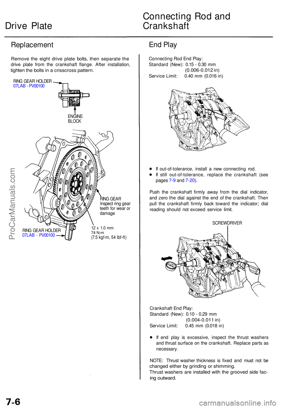
Remov e th e eigh t driv e plat e bolts , the n separat e th e
driv e plat e fro m th e crankshaf t flange . Afte r installation ,
tighten th e bolt s in a crisscros s pattern .
RING GEA R HOLDE R07LAB - PV0010 0
ENGINEBLOCK
RING GEA R HOLDE R07LAB - PV0010 0
RING GEA RInspec t rin g gea rteeth fo r wea r o rdamag e
12 x 1. 0 m m74 N- m(7.5 kgf-m , 5 4 Ibf-ft )
Connectin g Ro d En d Play :
Standar d (New) : 0.1 5 - 0.3 0 m m
(0.006-0.01 2 in )
Servic e Limit : 0.4 0 m m (0.01 6 in )
I f out-of-tolerance , instal l a ne w connectin g rod .
I f stil l out-of-tolerance , replac e th e crankshaf t (se e
page s 7- 9 an d 7-20 ).
Pus h th e crankshaf t firml y awa y fro m th e dia l indicator ,
an d zer o th e dia l agains t th e en d o f th e crankshaft . The n
pul l th e crankshaf t firml y bac k towar d th e indicator ; dia l
readin g shoul d no t excee d servic e limit .
SCREWDRIVE R
Crankshaft En d Play :
Standar d (New) : 0.1 0 - 0.2 9 m m
(0.004-0.01 1 in )
Servic e Limit : 0.4 5 m m (0.01 8 in )
I f en d pla y i s excessive , inspec t th e thrus t washer s
an d thrus t surfac e o n th e crankshaft . Replac e part s a s
necessary .
NOTE: Thrus t washe r thicknes s i s fixe d an d mus t no t b e
change d eithe r b y grindin g o r shimming .
Thrust washer s ar e installe d wit h th e groove d sid e fac -
ing outward .
ProCarManuals.com
Page 107 of 1771
Pistons and Crankshaft
Removal (cont'd)
5. Remove the bearing from the cap. Keep all caps/bear-
ings in order.
6. Remove the upper bearing halves from the connect-
ing rods and set them aside with their respective caps.
7. Reinstall the cap on the rod after removing each
piston/connecting rod assembly.
8. To avoid mixup on reassembly, mark each piston/con-
necting rod assembly with its cylinder number.
NOTE: The existing number on the connecting rod
does not indicate its position in the engine, it indicates
the rod bore size.
9. Remove the bearing cap bolts and bearing cap side
bolts, then remove the bearing caps.
MAIN BEARING
CAP
RUBBER
CAP
To help with removal of the caps, install the cap
bolts in the outside bolt holes.
CAP BOLT
MAIN BEARING CAPS
10. Lift the crankshaft out of the cylinder block, being
careful not to damage the journals.
CRANKSHAFT
11. Reinstall the main caps and bearings on the cylin-
der block in proper order.ProCarManuals.com
Page 108 of 1771
Crankshaft
Inspection
Clean the crankshaft oil passages with pipe cleaners
or a suitable brush.
Check the keyway and threads.
Alignment
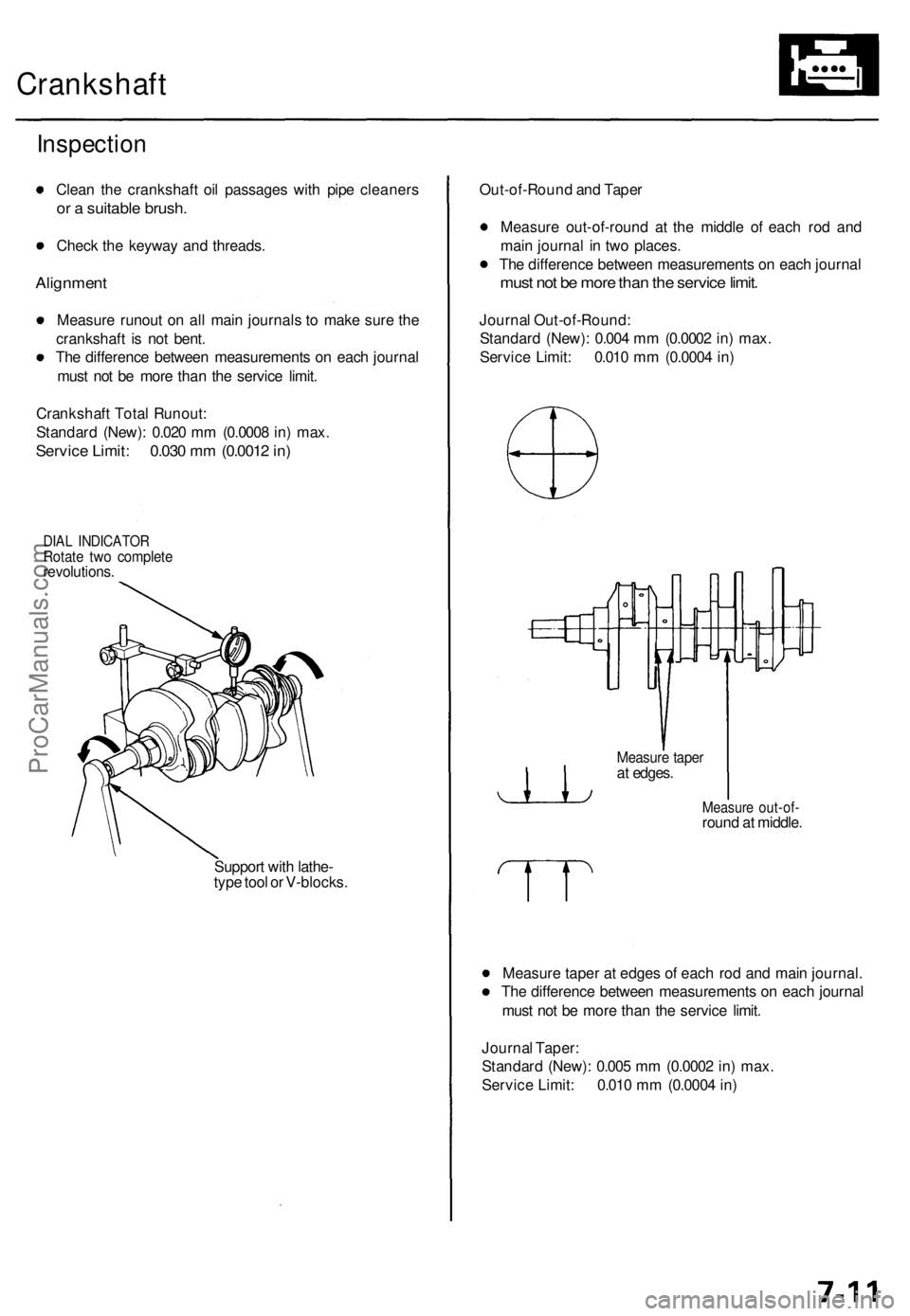
Measure runout on all main journals to make sure the
crankshaft is not bent.
The difference between measurements on each journal
must not be more than the service limit.
Crankshaft Total Runout:
Standard (New): 0.020 mm (0.0008 in) max.
Service Limit: 0.030 mm (0.0012 in)
DIAL INDICATOR
Rotate two complete
revolutions.
Support with lathe-
type tool or V-blocks.
Out-of-Round and Taper
Measure out-of-round at the middle of each rod and
main journal in two places.
The difference between measurements on each journal
must not be more than the service limit.
Journal Out-of-Round:
Standard (New): 0.004 mm (0.0002 in) max.
Service Limit: 0.010 mm (0.0004 in)
Measure out-of-
round at middle.
Measure taper at edges of each rod and main journal.
The difference between measurements on each journal
must not be more than the service limit.
Journal Taper:
Standard (New): 0.005 mm (0.0002 in) max.
Service Limit: 0.010 mm (0.0004 in)
Measure taper
at edges.ProCarManuals.com
Page 109 of 1771
Pistons
Inspectio n
1. Chec k th e pisto n fo r distortio n o r cracks .
NOTE : I f cylinde r i s bored , a n oversize d pisto n mus t
b e used .
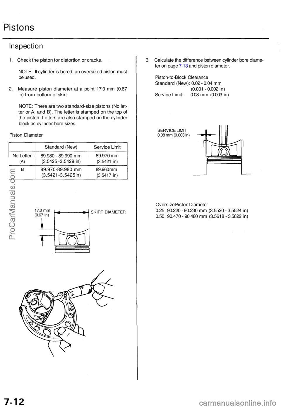
2 . Measur e pisto n diamete r a t a poin t 17. 0 m m (0.6 7
in) fro m botto m of skirt .
NOTE : Ther e ar e tw o standard-siz e piston s (N o let -
te r o r A , an d B) . Th e lette r i s stampe d o n th e to p o f
th e piston . Letter s ar e als o stampe d o n th e cylinde r
block a s cylinde r bor e sizes .
Piston Diamete r
N o Lette r
(A)
B
Standar d (New )
89.980 - 89.99 0 m m
(3.542 5 -3.542 9 in )
89.970-89.98 0 m m
(3.542 1 -3.542 5 in ) Servic
e Limi t
89.97 0 m m
(3.542 1 in )
89.96 0 mm
(3.541 7 in )
17. 0 mm(0.6 7 in) SKIR T DIAMETE R
3. Calculat e th e differenc e betwee n cylinde r bor e diame -
te r o n pag e 7-1 3 an d pisto n diameter .
Piston-to-Bloc k Clearanc e
Standard (New) : 0.0 2 - 0.0 4 m m
(0.00 1 - 0.00 2 in )
Servic e Limit : 0.0 8 m m (0.00 3 in )
SERVIC E LIMI T0.08 m m (0.00 3 in )
Oversiz e Pisto n Diamete r
0.25 : 90.22 0 - 90.23 0 m m (3.552 0 - 3.552 4 in )
0.50 : 90.47 0 - 90.48 0 m m (3.561 8 - 3.562 2 in )
ProCarManuals.com
Page 110 of 1771
Cylinder Bloc k
Inspectio n
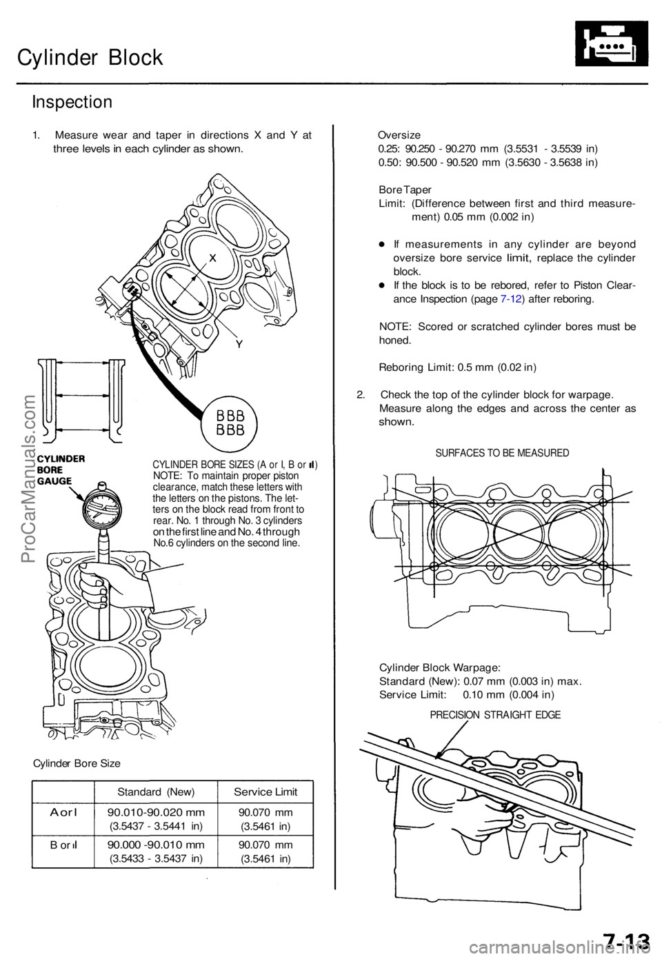
1. Measur e wea r an d tape r i n direction s X an d Y at
thre e level s in eac h cylinde r a s shown .
CYLINDE R BOR E SIZE S (A o r I , B or )NOTE : T o maintai n prope r pisto nclearance , matc h thes e letter s wit hthe letter s o n th e pistons . Th e let -ters o n th e bloc k rea d fro m fron t t orear . No . 1 throug h No . 3 cylinder son th e firs t lin e an d No . 4 throug hNo.6 cylinder s o n th e secon d line .
Cylinde r Bor e Siz e
A or I
B o r
Standar d (New )
90.010-90.02 0 m m
(3.543 7 - 3.544 1 in )
90.00 0 -90.01 0 m m
(3.543 3 - 3.543 7 in )
Servic e Limi t
90.07 0 m m
(3.546 1 in )
90.07 0 m m
(3.546 1 in )
Oversiz e
0.25: 90.25 0 - 90.27 0 m m (3.553 1 - 3.553 9 in )
0.50 : 90.50 0 - 90.52 0 m m (3.563 0 - 3.563 8 in )
Bor e Tape r
Limit : (Differenc e betwee n firs t an d thir d measure -
ment ) 0.0 5 m m (0.00 2 in )
I f measurement s i n an y cylinde r ar e beyon d
oversiz e bor e servic e
limit, replac e the cylinde r
block .
I f th e bloc k i s t o b e rebored , refe r t o Pisto n Clear -
anc e Inspectio n (pag e 7-12 ) afte r reboring .
NOTE : Score d o r scratche d cylinde r bore s mus t b e
honed .
Reborin g Limit : 0. 5 m m (0.0 2 in )
2 . Chec k th e to p o f th e cylinde r bloc k fo r warpage .
Measur e alon g th e edge s an d acros s th e cente r a s
shown .
SURFACE S T O B E MEASURE D
Cylinder Bloc k Warpage :
Standar d (New) : 0.0 7 m m (0.00 3 in ) max .
Servic e Limit : 0.1 0 m m (0.00 4 in )
PRECISIO N STRAIGH T EDG E
ProCarManuals.com
Page 111 of 1771
Cylinder Bloc k Piston Pin s
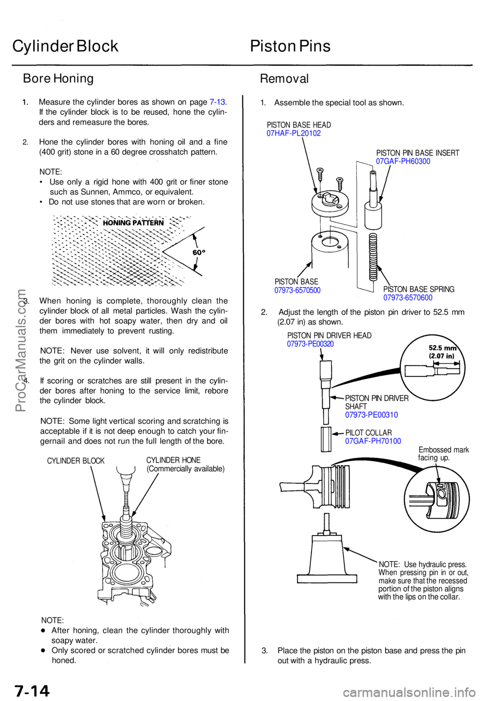
Bor e Honin g
2.
3.
4 .
Measur e th e cylinde r bore s a s show n o n pag e 7-13 .
I f th e cylinde r bloc k i s t o b e reused , hon e th e cylin -
der s an d remeasur e th e bores .
Hon e th e cylinde r bore s wit h honin g oi l an d a fin e
(40 0 grit ) ston e in a 60 degre e crosshatc h pattern .
NOTE:
• Us e onl y a rigi d hon e wit h 40 0 gri t o r fine r ston e
suc h a s Sunnen , Ammco , o r equivalent .
• D o no t us e stone s tha t ar e wor n o r broken .
Whe n honin g i s complete , thoroughl y clea n th e
cylinde r bloc k o f al l meta l particles . Was h th e cylin -
de r bore s wit h ho t soap y water , the n dr y an d oi l
the m immediatel y t o preven t rusting .
NOTE : Neve r us e solvent , i t wil l onl y redistribut e
th e gri t o n th e cylinde r walls .
I f scorin g o r scratche s ar e stil l presen t i n th e cylin -
de r bore s afte r honin g t o th e servic e limit , rebor e
th e cylinde r block .
NOTE : Som e ligh t vertica l scorin g an d scratchin g is
acceptabl e i f i t i s no t dee p enoug h t o catc h you r fin -
gernai l an d doe s no t ru n th e ful l lengt h o f th e bore .
CYLINDE R BLOC KCYLINDE R HON E(Commerciall y available )
NOTE:
After honing , clea n th e cylinde r thoroughl y wit h
soap y water .
Onl y score d o r scratche d cylinde r bore s mus t b e
honed .
Remova l
1. Assembl e th e specia l too l a s shown .
PISTON BAS E HEA D07HAF-PL2010 2
PISTON PI N BAS E INSER T07GAF-PH60300
PISTO N BAS E07973-657050 0 PISTO N BAS E SPRIN G07973-6570600
2 . Adjus t th e lengt h o f th e pisto n pi n drive r t o 52. 5 m m
(2.0 7 in ) a s shown .
PISTON PI N DRIVE R HEA D07973-PE0032 0
PISTON PI N DRIVE RSHAFT07973-PE0031 0
PILOT COLLA R07GAF-PH7010 0Embossed mar kfacin g up .
NOTE : Us e hydrauli c press .When pressin g pi n i n o r out ,mak e sur e tha t th e recesse dportion o f th e pisto n align swith th e lip s o n th e collar .
3. Plac e th e pisto n o n th e pisto n bas e an d pres s th e pi n
ou t wit h a hydrauli c press .
ProCarManuals.com
Page 118 of 1771
Crankshaft
Installation
Before installing the crankshaft, apply a coat of
engine oil to the main bearings and rod bearings.
1. Insert the bearing halves in the cylinder block and
connecting rods.
2. Lower the crankshaft into the block.
3. Install the thrust washers on the No. 4 journal. Oil
the thrust washer surfaces.
THRUST WASHERS
Grooved sides face
outward.ProCarManuals.com
Page 120 of 1771
Crankshaft
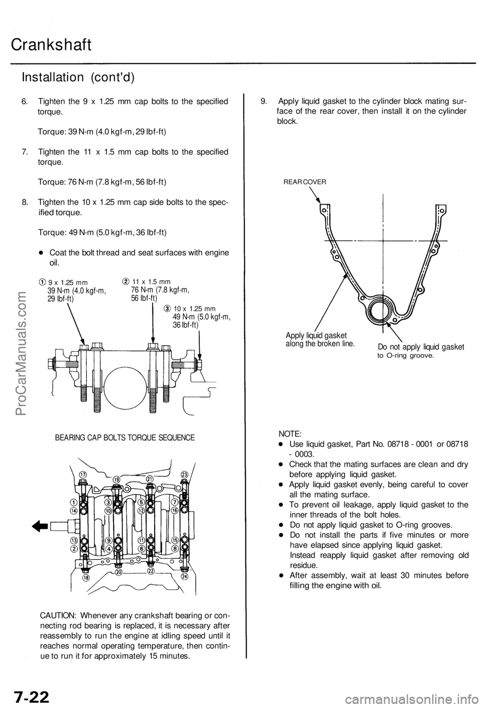
BEARING CAP BOLTS TORQUE SEQUENCE
CAUTION: Whenever any crankshaft bearing or con-
necting rod bearing is replaced, it is necessary after
reassembly to run the engine at idling speed until it
reaches normal operating temperature, then contin-
ue to run it for approximately 15 minutes.
9. Apply liquid gasket to the cylinder block mating sur-
face of the rear cover, then install it on the cylinder
block.
REAR COVER
Apply liquid gasket
along the broken line.
Do not apply liquid gasket
to O-ring groove.
NOTE:
Use liquid gasket, Part No. 08718 - 0001 or 08718
- 0003.
Check that the mating surfaces are clean and dry
before applying liquid gasket.
Apply liquid gasket evenly, being careful to cover
all the mating surface.
To prevent oil leakage, apply liquid gasket to the
inner threads of the bolt holes.
Do not apply liquid gasket to O-ring grooves.
Do not install the parts if five minutes or more
have elapsed since applying liquid gasket.
Instead reapply liquid gasket after removing old
residue.
After assembly, wait at least 30 minutes before
filling the engine with oil.
Installation (cont'd)
6. Tighten the 9 x 1.25 mm cap bolts to the specified
torque.
Torque: 39 N-m (4.0 kgf-m, 29 Ibf-ft)
7. Tighten the 11 x 1.5 mm cap bolts to the specified
torque.
Torque: 76 N-m (7.8 kgf-m, 56 Ibf-ft)
8. Tighten the 10 x 1.25 mm cap side bolts to the spec-
ified torque.
Torque: 49 N-m (5.0 kgf-m, 36 Ibf-ft)
Coat the bolt thread and seat surfaces with engine
oil.
9 x
1.25
mm
39 N-m (4.0 kgf-m,
29 Ibf-ft)
11 x 1.5 mm
76 N-m (7.8 kgf-m,
56 Ibf-ft)
10 x
1.25
mm
49 N-m (5.0 kgf-m,
36 Ibf-ft)ProCarManuals.com