Page 121 of 1771
NOTE:
Apply a light coat of oil to the crankshaft and to the
lip of the oil seal.
Use a new O-ring and apply oil when installing it.
Use new special bolts when installing the rear
cover.
DOWEL PINS
REAR COVER
6 x 1.0 mm
12 N-m (1.2 kgf-m,
8.7 Ibf-ft)
Replace.
O-RING
Replace.
10. Apply liquid gasket to the cylinder block mating sur-
face of the oil pump.
NOTE: Do not apply liquid gasket to O-ring grooves.
OIL PUMP
HOUSING
Apply liquid gasket
along the broken line.
NOTE:
Apply a light coat of oil to the crankshaft and to
the lip of the seal.
Use new O-rings and apply oil when installing
them.
Use new special bolts when installing the oil
pump housing.
11. Install the oil pump with new O-rings.
DOWEL PIN
OIL PUMP
DOWEL PIN
10 x
1.25
mm
44 N-m (4.5 kgf-m,
33 Ibf-ft)
6 x 1.0 mm
12 N-m (1.2 kgf-m,
8.7 Ibf-ft)
8 x
1.25
mm
22 N-m (2.2 kgf-m,
16 Ibf-ft)
O-RING GROOVE
O-RINGS
Replace.
O-RINGS
Replace.
O-RING GROOVEProCarManuals.com
Page 122 of 1771
Crankshaft
Installation (cont'd)
12. Apply liquid gasket to the cylinder block, then install
the oil
pan.
CYLINDER
BLOCK
O-RING
GROOVE Apply liquid gasket
along the broken line.
NOTE:
• Do not apply liquid gasket to the O-ring grooves.
• Use new O-rings and apply oil when installing
them.
O-RINGS
Replace.
DOWEL PIN
DOWEL PIN
OIL PAN
ASSEMBLY
8 x
1.25
mm
22 N-m (2.2 kgf-m,
16 Ibf-ft)
13. Tighten the oil pan bolts as shown.
OIL PAN BOLT TIGHTENING SEQUENCE
8 x 1.25 mm: 22 N-m (2.2 kgf-m, 16 Ibf-ft)ProCarManuals.com
Page 133 of 1771

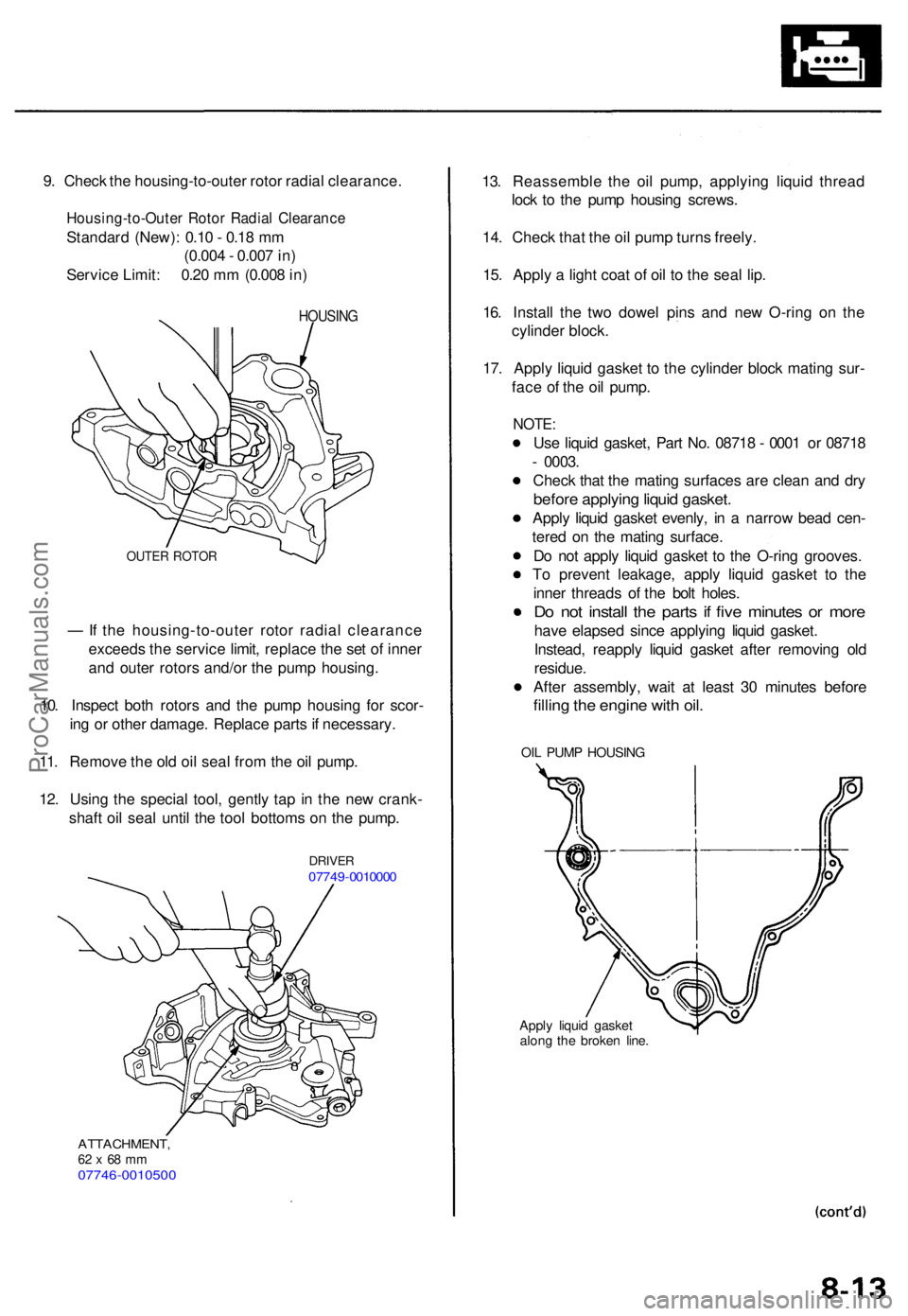
9. Chec k th e housing-to-oute r roto r radia l clearance .
Housing-to-Oute r Roto r Radia l Clearanc e
Standard (New) : 0.1 0 - 0.1 8 m m
(0.00 4 - 0.00 7 in )
Servic e Limit : 0.2 0 m m (0.00 8 in )
HOUSIN G
OUTER ROTO R
— If th e housing-to-oute r roto r radia l clearanc e
exceed s th e servic e limit , replac e th e se t o f inne r
an d oute r rotor s and/o r th e pum p housing .
10 . Inspec t bot h rotor s an d th e pum p housin g fo r scor -
in g o r othe r damage . Replac e part s if necessary .
11 . Remov e th e ol d oi l sea l fro m th e oi l pump .
12 . Usin g th e specia l tool , gentl y ta p i n th e ne w crank -
shaf t oi l sea l unti l th e too l bottom s o n th e pump .
DRIVE R07749-001000 0
ATTACHMENT ,62 x 68 m m07746-001050 0
13. Reassembl e th e oi l pump , applyin g liqui d threa d
loc k t o th e pum p housin g screws .
14 . Chec k tha t th e oi l pum p turn s freely .
15 . Appl y a ligh t coa t o f oi l t o th e sea l lip .
16 . Instal l th e tw o dowe l pin s an d ne w O-rin g o n th e
cylinde r block .
17 . Appl y liqui d gaske t t o th e cylinde r bloc k matin g sur -
fac e o f th e oi l pump .
NOTE:
Use liqui d gasket , Par t No . 0871 8 - 000 1 o r 0871 8
- 0003 .
Chec k tha t th e matin g surface s ar e clea n an d dr y
befor e applyin g liqui d gasket .
Apply liqui d gaske t evenly , i n a narro w bea d cen -
tere d o n th e matin g surface .
D o no t appl y liqui d gaske t t o th e O-rin g grooves .
T o preven t leakage , appl y liqui d gaske t t o th e
inne r thread s o f th e bol t holes .
Do no t instal l th e part s i f fiv e minute s o r mor e
have elapse d sinc e applyin g liqui d gasket .
Instead , reappl y liqui d gaske t afte r removin g ol d
residue .
Afte r assembly , wai t a t leas t 3 0 minute s befor e
filling th e engin e wit h oil .
OIL PUM P HOUSIN G
Apply liqui d gaske t
alon g th e broke n line .
ProCarManuals.com
Page 134 of 1771
Oil Pum p
10 x 1.2 5 mm44 N- m (4. 5 kgf-m ,
3 3 Ibf-ft )
DOWE L PI N O-RING S
Replace.
6 x 1. 0 m m12 N- m (1. 2 kgf-m ,
8. 7 Ibf-ft )
OILPUM P
O-RING SReplace .
DOWELPIN
8 x 1.2 5 mm22 N- m (2. 2 kgf-m ,
1 6 Ibf-ft )
19. Instal l th e oi l pa n (se e pag e 8-9 ).
20 . Instal l th e timin g bel t (se e pag e 6-8 ).
Removal/lnspection/lnstallatio n
(cont'd )
18. Instal l th e oi l pum p to th e cylinde r block .
ProCarManuals.com
Page 136 of 1771
Exhaust Manifol d
Replacemen t
NOTE: Us e ne w gasket s an d self-lockin g nut s whe n reassembling .
LEFT:
10 x 1.2 5 mm25 N- m (2. 5 kgf-m ,
1 8 Ibf-ft )
GASKE TReplace .
SELF-LOCKIN G NU T8 x 1.2 5 mm30 N- m (3. 1 kgf-m ,22 Ibf-ft )Replace .
LEFT PRIMAR Y
HEATE D OXYGE N
SENSO R (LEF T
PRIMAR Y HO2S )
Replacement , pag e 9- 5
LEF T EXHAUS T
MANIFOL D
8 x 1.2 5 mm22 N- m (2. 2 kgf-m , 1 6 Ibf-ft )
RIGHT :
8 x 1.2 5 mm22 N- m (2. 2 kgf-m , 1 6 Ibf-ft )
HEATSHIEL D
RIGH T PRIMAR Y
HEATED OXYGE NSENSOR (RIGH T
PRIMAR Y HO2S )
Replacement , pag e 9- 5
COVE R
GASKE TReplace .
RIGHT EXHAUS TMANIFOLD
SELF-LOCKIN G NU T8 x 1.2 5 mm30 N- m (3. 1 kgf-m , 2 2 Ibf-ft )Replace .
8 x 1.2 5 mm22 N- m (2. 2 kgf-m ,
1 6 Ibf-ft )
COVE R
HEATSHIEL D
ProCarManuals.com
Page 137 of 1771

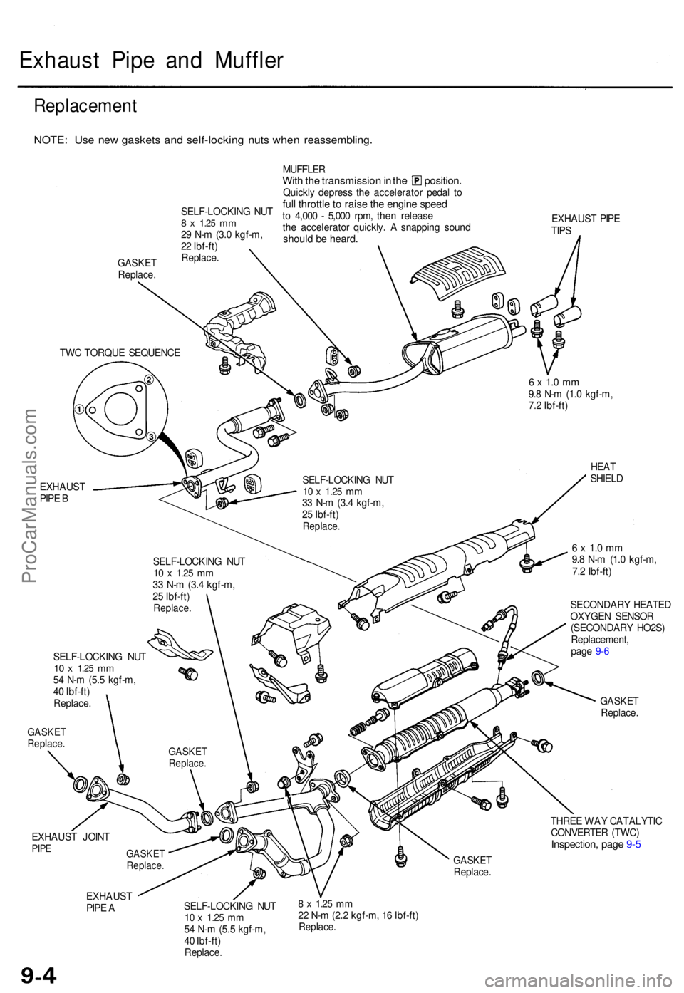
Exhaust Pip e an d Muffle r
Replacemen t
NOTE: Us e ne w gasket s an d self-lockin g nut s whe n reassembling .
GASKETReplace . MUFFLE
R
With th e transmissio n in th e position .Quickly depres s th e accelerato r peda l t oful l throttl e to rais e th e engin e spee dto 4,00 0 - 5,00 0 rpm , the n releas e
th e accelerato r quickly . A snappin g soun d
should b e heard .
EXHAUS T PIP E
TIP S
EXHAUS T
PIP E B
6 x 1. 0 m m9.8 N- m (1. 0 kgf-m ,
7. 2 Ibf-ft )
HEAT
SHIEL D
GASKE TReplace .
6 x 1. 0 m m9.8 N- m (1. 0 kgf-m ,
7. 2 Ibf-ft )
SECONDAR Y HEATE D
OXYGE N SENSO R
(SECONDAR Y HO2S )
Replacement ,
pag e 9- 6
GASKE TReplace .
EXHAUS T JOIN T
PIPE
THRE E WA Y CATALYTI C
CONVERTE R (TWC )
Inspection , pag e 9- 5
GASKE TReplace .
EXHAUS T
PIP E A SELF-LOCKIN
G NU T
10 x 1.2 5 mm54 N- m (5. 5 kgf-m ,
4 0 Ibf-ft )
Replace .
8 x 1.2 5 mm22 N- m (2. 2 kgf-m , 1 6 Ibf-ft )Replace .
TWC TORQU E SEQUENC E
SELF-LOCKING NU T
10 x 1.2 5 mm33 N- m (3. 4 kgf-m ,
2 5 Ibf-ft )
Replace .
SELF-LOCKIN G NU T10 x 1.2 5 mm33 N- m (3. 4 kgf-m ,
2 5 Ibf-ft )
Replace .
SELF-LOCKIN G NU T10 x 1.2 5 mm54 N- m (5. 5 kgf-m ,
4 0 Ibf-ft )
Replace .
GASKETReplace .
GASKETReplace .
SELF-LOCKIN G NU T8 x 1.2 5 mm29 N- m (3. 0 kgf-m ,
2 2 Ibf-ft )
Replace .
ProCarManuals.com
Page 144 of 1771

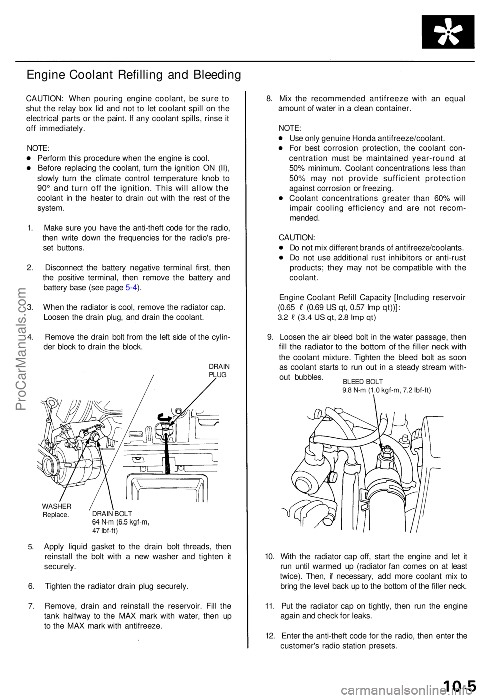
Engine Coolan t Refillin g an d Bleedin g
CAUTION : Whe n pourin g engin e coolant , b e sur e t o
shu t th e rela y bo x li d an d no t t o le t coolan t spil l o n th e
electrica l part s o r th e paint . I f an y coolan t spills , rins e it
of f immediately .
NOTE:
Perfor m thi s procedur e whe n th e engin e is cool .
Befor e replacin g th e coolant , tur n th e ignitio n O N (II) ,
slowl y tur n th e climat e contro l temperatur e kno b t o
90 ° an d tur n of f th e ignition . Thi s wil l allo w th e
coolan t i n th e heate r t o drai n ou t wit h th e res t o f th e
system .
1 . Mak e sur e yo u hav e th e anti-thef t cod e fo r th e radio ,
the n writ e dow n th e frequencie s fo r th e radio' s pre -
se t buttons .
2 . Disconnec t th e batter y negativ e termina l first , the n
th e positiv e terminal , the n remov e th e batter y an d
batter y bas e (se e pag e 5-4 ).
3 . Whe n th e radiato r i s cool , remov e th e radiato r cap .
Loose n th e drai n plug , an d drai n th e coolant .
4 . Remov e th e drai n bol t fro m th e lef t sid e o f th e cylin -
de r bloc k t o drai n th e block .
DRAINPLUG
5.
WASHE RReplace .DRAIN BOL T64 N- m (6. 5 kgf-m ,
4 7 Ibf-ft )
Apply liqui d gaske t t o th e drai n bol t threads , the n
reinstal l th e bol t wit h a ne w washe r an d tighte n i t
securely .
6. Tighte n th e radiato r drai n plu g securely .
7 . Remove , drai n an d reinstal l th e reservoir . Fil l th e
tan k halfwa y t o th e MA X mar k wit h water , the n u p
t o th e MA X mar k wit h antifreeze . 8
. Mi x th e recommende d antifreez e wit h a n equa l
amoun t o f wate r i n a clea n container .
NOTE:
Use onl y genuin e Hond a antifreeze/coolant .
Fo r bes t corrosio n protection , th e coolan t con -
centratio n mus t b e maintaine d year-roun d a t
50 % minimum . Coolan t concentration s les s tha n
50 % ma y no t provid e sufficien t protectio n
agains t corrosio n o r freezing .
Coolan t concentration s greate r tha n 60 % wil l
impai r coolin g efficienc y an d ar e no t recom -
mended .
CAUTION :
D o no t mi x differen t brand s o f antifreeze/coolants .
D o no t us e additiona l rus t inhibitor s o r anti-rus t
products ; the y ma y no t b e compatibl e wit h th e
coolant .
Engine Coolan t Refil l Capacit y [Includin g reservoi r
(0.65 (0.6 9 U S qt , 0.5 7 Im p qt))] :
3.2 (3. 4 US qt , 2. 8 Im p qt )
9. Loose n th e ai r blee d bol t i n th e wate r passage , the n
fill th e radiato r t o th e botto m o f th e fille r nec k wit h
the coolan t mixture . Tighte n th e blee d bol t a s soo n
a s coolan t start s t o ru n ou t i n a stead y strea m with -
ou t bubbles .
10 . Wit h th e radiato r ca p off , star t th e engin e an d le t i t
ru n unti l warme d u p (radiato r fa n come s o n a t leas t
twice) . Then , i f necessary , ad d mor e coolan t mi x t o
brin g th e leve l bac k u p to th e botto m o f th e fille r neck .
11 . Pu t th e radiato r cap on tightly , the n ru n th e engin e
agai n an d chec k fo r leaks .
12 . Ente r th e anti-thef t cod e fo r th e radio , the n ente r th e
customer' s radi o statio n presets .
BLEED BOL T9.8 N- m (1. 0 kgf-m , 7. 2 Ibf-ft )
ProCarManuals.com
Page 149 of 1771
Water Pum p
Inspectio n
1. Remov e th e timin g bel t (se e pag e 6-6 ).
2 . Tur n th e wate r pum p pulle y counterclockwise .
Check tha t i t turn s freely .
3. Chec k fo r sign s o f sea l leakage .
NOTE: A smal l amoun t o f "weeping " fro m th e blee d
hole is normal .
BLEED HOL E
Replacemen t
1. Remov e th e timin g bel t (se e pag e 6-6 ).
2 . Remov e th e lef t camshaf t pulle y an d bac k cove r
(se e pag e 6-19 ).
3 . Remov e th e wate r pump .
NOTE: Inspect , repai r an d clea n th e O-rin g groov e
and matin g surfac e wit h th e cylinde r block .
8 x 1.2 5 mm22 N- m (2. 2 kgf-m ,
1 6 Ibf-ft )
O-RIN GReplace .
DOWE L
PIN
DOWE L PI N
O-RIN G
Replace .
WATER8 x 1.2 5 m m \ PUM P22 N- m (2. 2 kgf-m , 6 x 1. 0 m m
1 6 Ibf-ft ) 1 2 N- m (1. 2 kgf-m ,
8. 7 Ibf-ft )
4. Instal l th e wate r pum p in th e revers e orde r o f removal .
NOTE :
Keep th e O-rin g in positio n whe n installing .
Clean th e spille d engin e coolant .
ProCarManuals.com