1995 ACURA TL lock
[x] Cancel search: lockPage 303 of 1771
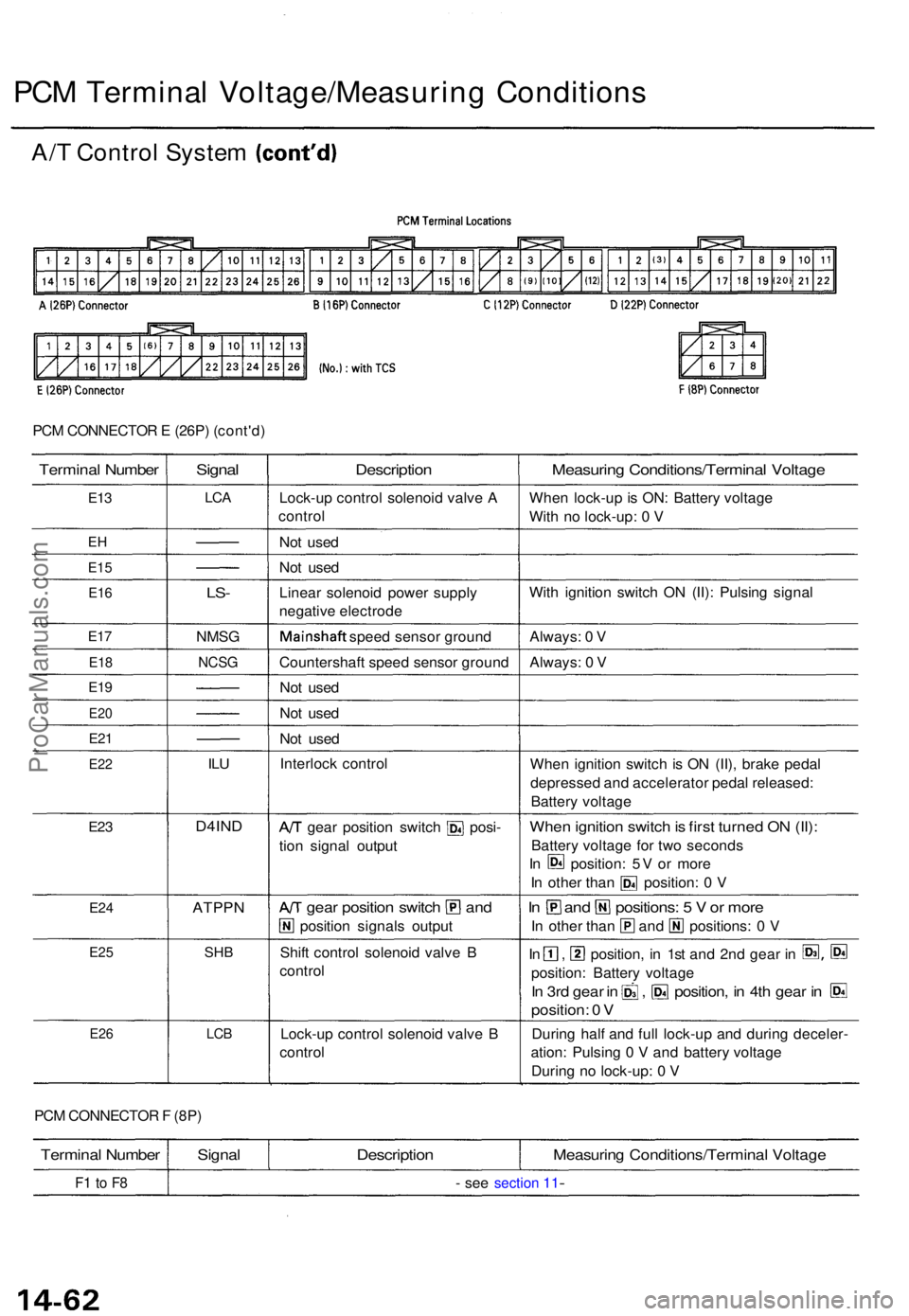
PCM CONNECTO R E (26P ) (cont'd )
Termina l Numbe r
E13
EH
E1 5
E16
E17
E1 8
E19
E2 0
E21
E2 2
E23
E2 4
E2 5
E2 6
Signa l
LCA
LS-
NMS G
NCSG
ILU
D4IN D
ATPP N
SHB
LCB
Descriptio n
Lock-up contro l solenoi d valv e A
contro l
No t use d
No t use d
Linea r solenoi d powe r suppl y
negativ e electrod e
Mainshaf t speed senso r groun d
Countershaf t spee d senso r groun d
No t use d
No t use d
No t use d
Interloc k contro l
A/T gea r positio n switc h posi -
tio n signa l outpu t
A/T gea r positio n switc h an d
positio n signal s outpu t
Shif t contro l solenoi d valv e B
contro l
Lock-u p contro l solenoi d valv e B
contro l
Measurin g Conditions/Termina l Voltag e
When lock-u p is ON : Batter y voltag e
Wit h n o lock-up : 0 V
Wit h ignitio n switc h O N (II) : Pulsin g signa l
Always : 0 V
Always : 0 V
Whe n ignitio n switc h i s O N (II) , brak e peda l
depresse d an d accelerato r peda l released :
Batter y voltag e
When ignitio n switc h is firs t turne d O N (II) :
Batter y voltag e fo r tw o second s
In position : 5 V o r mor e
In othe r tha n position : 0 V
In an d positions : 5 V or mor e
In othe r tha n an d positions : 0 V
In , position , i n 1s t an d 2n d gea r i n S3 , @
position : Batter y voltag e
In 3r d gea r i n , position , i n 4t h gea r i n E
position : 0 V
Durin g hal f an d ful l lock-u p an d durin g deceler -
ation : Pulsin g 0 V an d batter y voltag e
Durin g n o lock-up: 0 V
PC M CONNECTO R F (8P )
Termina l Numbe r
F1 t o F 8
Signa lDescriptio nMeasuring Conditions/Termina l Voltag e
- se e section 11-
A/ T Contro l Syste m (cont'd )
PCM Termina l Voltage/Measurin g Condition s
ProCarManuals.com
Page 304 of 1771
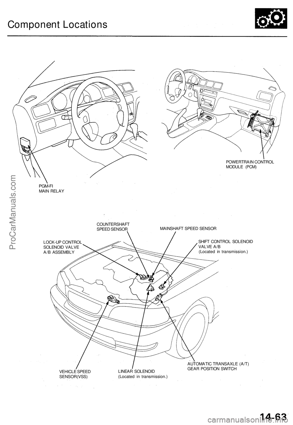
Component Locations
POWERTRAIN CONTROL
MODULE (PCM)
PGM-FI
MAIN RELAY
COUNTERSHAFT
SPEED SENSOR
MAINSHAFT SPEED SENSOR
LOCK-UP CONTROL
SOLENOID VALVE
A/B ASSEMBLY
SHIFT CONTROL SOLENOID
VALVE A/B
(Located in transmission.)
VEHICLE SPEED
SENSOR(VSS)
LINEAR SOLENOID
(Located in transmission.)
AUTOMATIC TRANSAXLE (A/T)
GEAR POSITION SWITCHProCarManuals.com
Page 309 of 1771
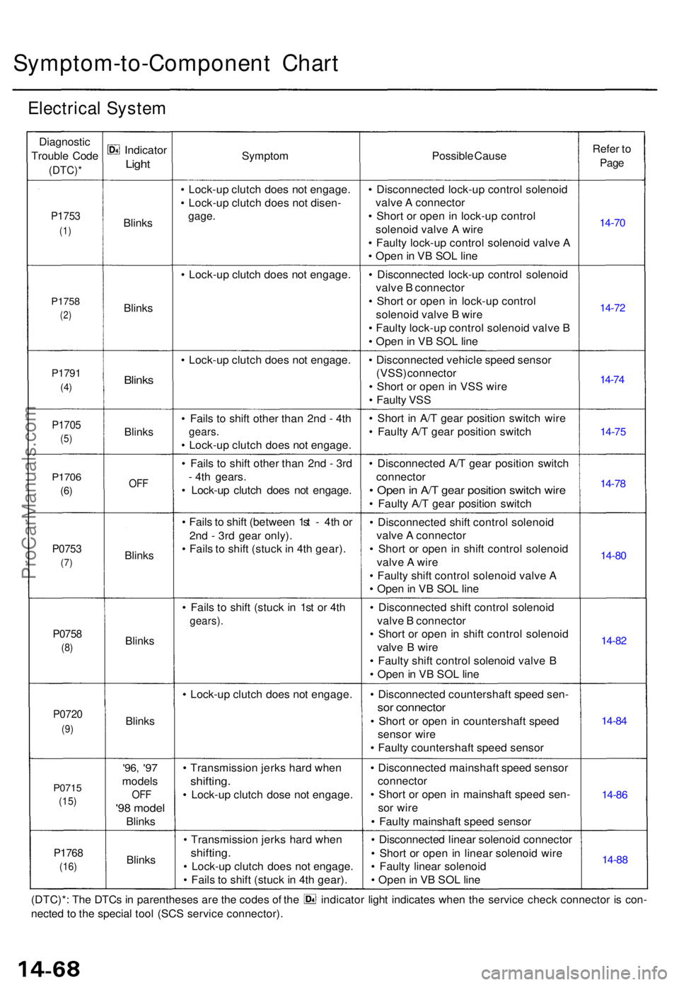
Symptom-to-Component Char t
Electrica l Syste m
Diagnosti c
Troubl e Cod e
(DTC) *
P1753
(1)
P175 8
(2)
P179 1
(4)
P170 5
(5)
P170 6
(6)
P075 3
(7)
P075 8
(8)
P072 0
(9)
P071 5
(15)
P176 8
(16)
Indicato r
Light
Blink s
Blink s
Blinks
Blink s
OFF
Blink s
Blink s
Blinks
'96, '97
model s
OFF
'98 mode l
Blinks
Blink s
Sympto m
• Lock-u p clutc h doe s no t engage .
• Lock-u p clutc h doe s no t disen -
gage.
• Lock-u p clutc h doe s no t engage .
• Lock-u p clutc h doe s no t engage .
• Fail s t o shif t othe r tha n 2n d - 4t h
gears .
• Lock-u p clutc h doe s no t engage .
• Fail s t o shif t othe r tha n 2n d - 3r d
- 4t h gears .
• Lock-u p clutc h doe s no t engage .
• Fail s to shif t (betwee n 1s t - 4t h o r
2n d - 3r d gea r only) .
• Fail s t o shif t (stuc k in 4t h gear) .
• Fail s t o shif t (stuc k i n 1s t o r 4t h
gears) .
• Lock-u p clutc h doe s no t engage .
• Transmissio n jerk s har d whe n
shifting .
• Lock-u p clutc h dos e no t engage .
• Transmissio n jerk s har d whe n
shifting .
• Lock-u p clutc h doe s no t engage .
• Fail s t o shif t (stuc k in 4t h gear) . Possibl
e Caus e
• Disconnecte d lock-u p contro l solenoi d
valv e A connecto r
• Shor t o r ope n i n lock-u p contro l
solenoi d valv e A wir e
• Fault y lock-u p contro l solenoi d valv e A
• Ope n in V B SO L lin e
• Disconnecte d lock-u p contro l solenoi d
valv e B connecto r
• Shor t o r ope n in lock-u p contro l
solenoi d valv e B wir e
• Fault y lock-u p contro l solenoi d valv e B
• Ope n in V B SO L lin e
• Disconnecte d vehicl e spee d senso r
(VSS) connecto r
• Shor t o r ope n in VS S wir e
• Fault y VS S
• Shor t i n A/ T gea r positio n switc h wir e
• Fault y A/ T gea r positio n switc h
• Disconnecte d A/ T gea r positio n switc h
connecto r
• Ope n in A/ T gea r positio n switc h wir e
• Fault y A/ T gea r positio n switc h
• Disconnecte d shif t contro l solenoi d
valv e A connecto r
• Shor t o r ope n i n shif t contro l solenoi d
valv e A wir e
• Fault y shif t contro l solenoi d valv e A
• Ope n in V B SO L lin e
• Disconnecte d shif t contro l solenoi d
valv e B connecto r
• Shor t o r ope n i n shif t contro l solenoi d
valv e B wir e
• Fault y shif t contro l solenoi d valv e B
• Ope n in V B SOL line
• Disconnecte d countershaf t spee d sen -
sor connecto r
• Shor t o r ope n i n countershaf t spee d
senso r wir e
• Fault y countershaf t spee d senso r
• Disconnecte d mainshaf t spee d senso r
connecto r
• Shor t o r ope n i n mainshaf t spee d sen -
so r wir e
• Fault y mainshaf t spee d senso r
• Disconnecte d linea r solenoi d connecto r
• Shor t o r ope n i n linea r solenoi d wir e
• Fault y linea r solenoi d
• Ope n in V B SOL line Refe
r t o
Pag e
14-7 0
14-72
14-74
14-7 5
14-78
14-8 0
14-82
14-84
14-8 6
14-8 8
(DTC)* : Th e DTC s in parenthese s ar e th e code s o f th e indicato r ligh t indicate s whe n th e servic e chec k connecto r i s con -
necte d to th e specia l too l (SC S servic e connector) .
ProCarManuals.com
Page 310 of 1771
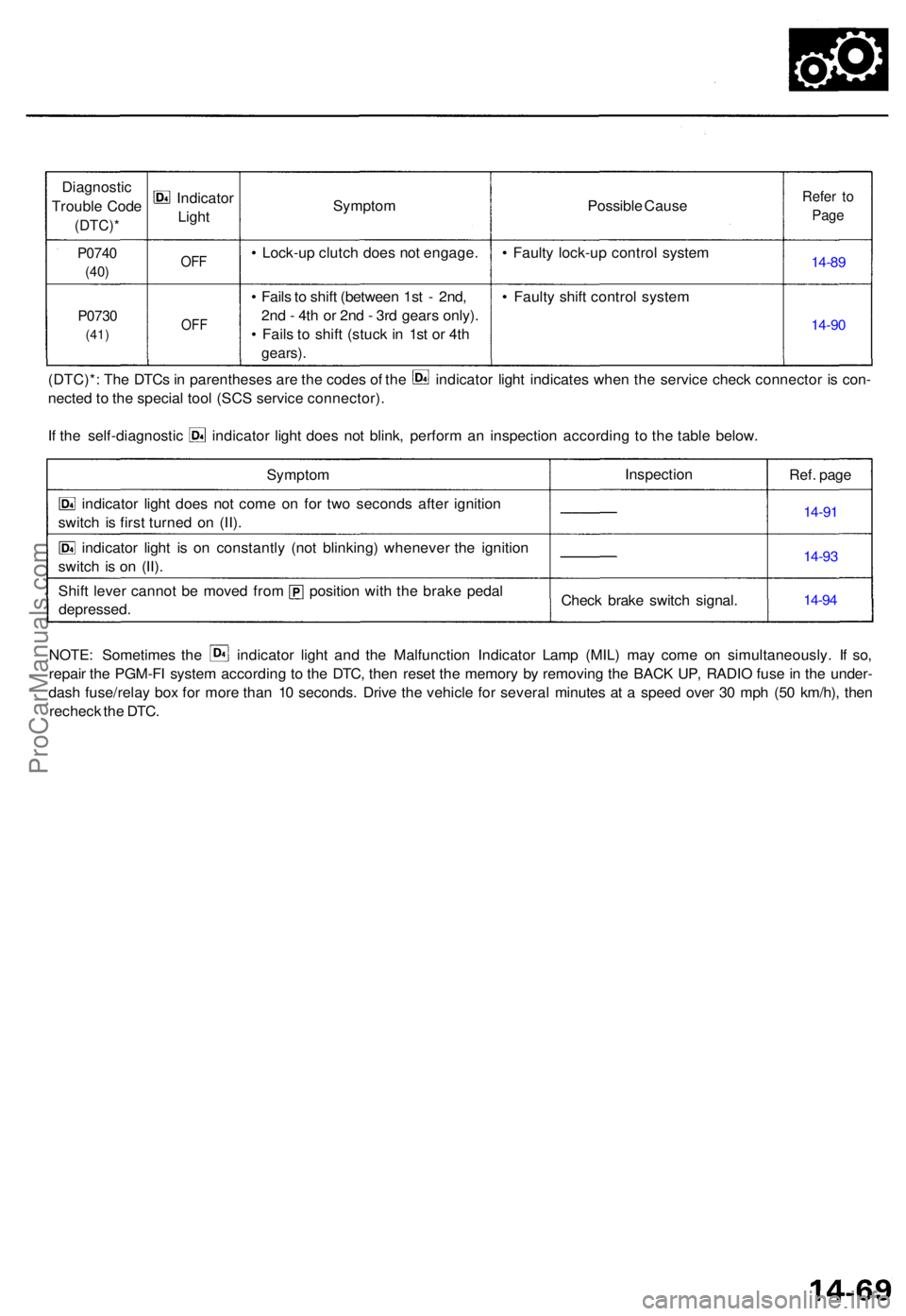
Diagnostic
Troubl e Cod e
(DTC) *
P0740
(40)
P073 0
(41)
Indicato r
Ligh t
OFF
OF F
Sympto m
• Lock-u p clutc h doe s no t engage .
• Fail s to shif t (betwee n 1s t - 2nd ,
2n d - 4t h o r 2n d - 3r d gear s only) .
• Fail s t o shif t (stuc k i n 1s t o r 4t h
gears) .
Possibl e Caus e
• Fault y lock-u p contro l syste m
• Fault y shif t contro l syste mRefer t o
Pag e
14-8 9
14-9 0
(DTC)* : Th e DTC s in parenthese s ar e th e code s o f th e indicato r ligh t indicate s whe n th e servic e chec k connecto r i s con -
necte d t o th e specia l too l (SC S servic e connector) .
If th e self-diagnosti c indicato r ligh t doe s no t blink , perfor m a n inspectio n accordin g t o th e tabl e below .
Sympto m
indicato r ligh t doe s no t com e o n fo r tw o second s afte r ignitio n
switc h i s firs t turne d o n (II) .
indicato r ligh t i s o n constantl y (no t blinking ) wheneve r th e ignitio n
switc h i s o n (II) .
Shif t leve r canno t b e move d fro m positio n wit h th e brak e peda l
depressed . Inspectio
n
Chec k brak e switc h signal . Ref.
page
14-9 1
14-9 3
14-9 4
NOTE : Sometime s th e indicato r ligh t an d th e Malfunctio n Indicato r Lam p (MIL ) ma y com e o n simultaneously . I f so ,
repai r th e PGM-F I syste m accordin g t o th e DTC , the n rese t th e memor y b y removin g th e BAC K UP , RADI O fus e in th e under -
das h fuse/rela y bo x fo r mor e tha n 1 0 seconds . Driv e th e vehicl e fo r severa l minute s a t a spee d ove r 3 0 mp h (5 0 km/h) , the n
rechec k th e DTC .
ProCarManuals.com
Page 311 of 1771
Lock-up Contro l Solenoi d Valv e A/ B
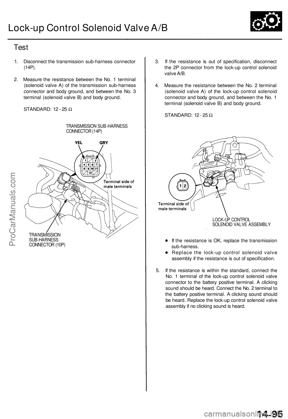
Tes t
STANDARD : 1 2 - 2 5 W
1
. Disconnec t th e transmissio n sub-harnes s connecto r
(14P).
2. Measur e th e resistanc e betwee n th e No . 1 termina l
(solenoi d valv e A ) o f th e transmissio n sub-harnes s
connecto r an d bod y ground , an d betwee n th e No . 3
termina l (solenoi d valv e B ) an d bod y ground .
TRANSMISSIO N SUB-HARNES SCONNECTOR (14P )
TRANSMISSIO NSUB-HARNESSCONNECTOR (10P )
5. I f th e resistanc e i s withi n th e standard , connec t th e
No . 1 termina l o f th e lock-u p contro l solenoi d valv e
connecto r t o th e batter y positiv e terminal . A clickin g
soun d shoul d b e heard . Connec t th e No . 2 termina l t o
th e batter y positiv e terminal . A clickin g soun d shoul d
b e heard . Replac e th e lock-u p contro l solenoi d valv e
assembl y if n o clickin g soun d is heard .
I
f th e resistanc e i s OK , replac e th e transmissio n
sub-harness .
Replace th e lock-u p contro l solenoi d valv e
assembl y if th e resistanc e is ou t o f specification .
LOCK-UP CONTRO LSOLENOID VALV E ASSEMBL Y
3. I f th e resistanc e i s ou t o f specification , disconnec t
th e 2 P connecto r fro m th e lock-u p contro l solenoi d
valv e A/B .
4 . Measur e th e resistanc e betwee n th e No . 2 termina l
(solenoi d valv e A ) o f th e lock-u p contro l solenoi d
connecto r an d bod y ground , an d betwee n th e No . 1
termina l (solenoi d valv e B ) an d bod y ground .
STANDARD : 1 2 - 2 5 W
ProCarManuals.com
Page 312 of 1771
Lock-up Contro l Solenoi d Valve A/B
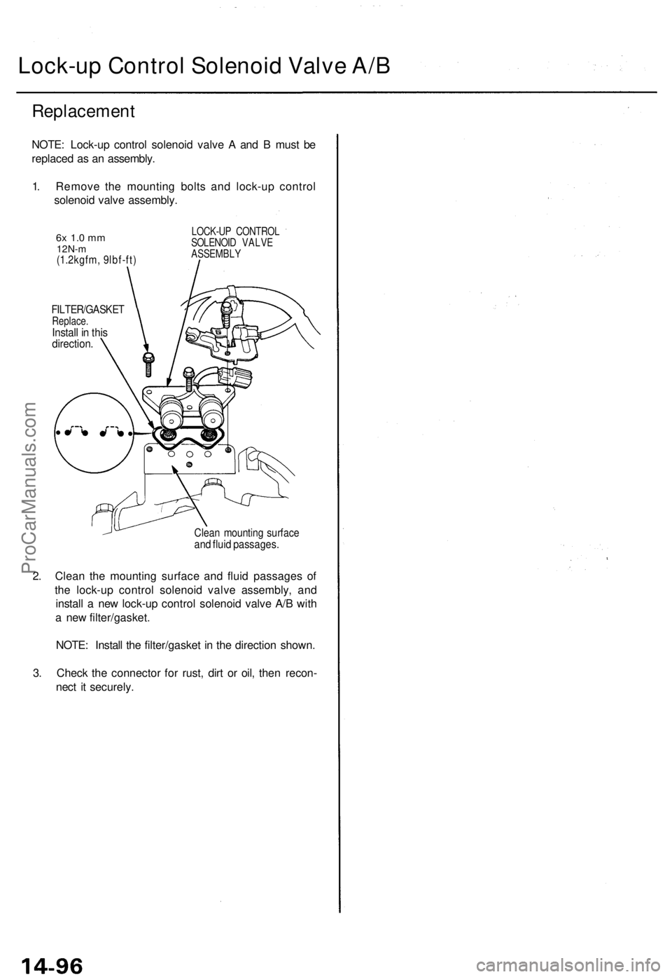
Replacemen t
NOTE: Lock-u p contro l solenoi d valv e A an d B mus t b e
replace d a s a n assembly .
1 . Remov e th e mountin g bolt s an d lock-u p contro l
solenoi d valv e assembly .
2 . Clea n th e mountin g surfac e an d flui d passage s o f
th e lock-u p contro l solenoi d valv e assembly , an d
instal l a ne w lock-u p contro l solenoi d valv e A/ B wit h
a ne w filter/gasket .
NOTE : Instal l th e filter/gaske t i n th e directio n shown .
3 . Chec k th e connecto r fo r rust , dir t o r oil , the n recon -
nec t i t securely .
Clean mountin g surfac eand flui d passages .
FILTER/GASKE TReplace.Install i n thi sdirection .
6x 1. 0 m m12N- m(1.2kgfm , 9lbf-ft )
LOCK-U P CONTRO L
SOLENOI D VALV E
ASSEMBL Y
ProCarManuals.com
Page 317 of 1771
A/T Gea r Positio n Switc h
Replacemen t
Make sur e lifts , jack s an d safet y stand s ar e
place d properly , an d hois t bracket s ar e attache d to th e
correc t positio n o n th e engin e (se e sectio n 1 ).
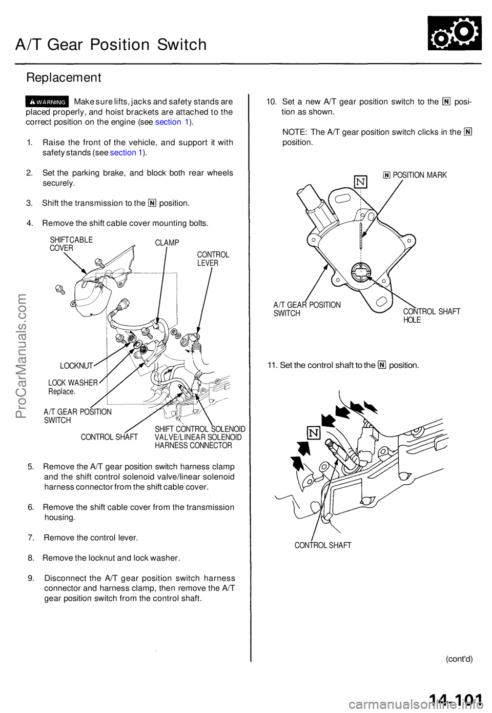
1 . Rais e th e fron t o f th e vehicle , an d suppor t i t wit h
safet y stand s (se e sectio n 1 ).
2 . Se t th e parkin g brake , an d bloc k bot h rea r wheel s
securely .
3. Shif t th e transmissio n t o th e position .
4 . Remov e th e shif t cabl e cove r mountin g bolts .
CLAM P
SHIF
T CABL ECOVERCONTRO LLEVER
CONTRO L SHAF T SHIF
T CONTRO L SOLENOI DVALVE/LINEA R SOLENOI DHARNESS CONNECTO R
5. Remov e th e A/ T gea r positio n switc h harnes s clam p
an d th e shif t contro l solenoi d valve/linea r solenoi d
harnes s connecto r fro m th e shif t cabl e cover .
6 . Remov e th e shif t cabl e cove r fro m th e transmissio n
housing .
7 . Remov e th e contro l lever .
8 . Remov e th e locknu t an d loc k washer .
9 . Disconnec t th e A/ T gea r positio n switc h harnes s
connecto r an d harnes s clamp , the n remov e th e A/ T
gea r positio n switc h fro m th e contro l shaft .
10. Se t a ne w A/ T gea r positio n switc h t o th e posi -
tio n a s shown .
NOTE: Th e A/ T gea r positio n switc h click s in th e
position .
POSITIO N MAR K
A/ T GEA R POSITIO N
SWITC H CONTRO
L SHAF T
HOL E
11. Se t th e contro l shaf t t o th e position .
CONTROL SHAF T
(cont'd )
LOCKNU T
LOCK WASHE RReplace.
A/T GEA R POSITIO N
SWITC H
ProCarManuals.com
Page 318 of 1771
A/T Gea r Positio n Switc h
Replacemen t (cont'd )
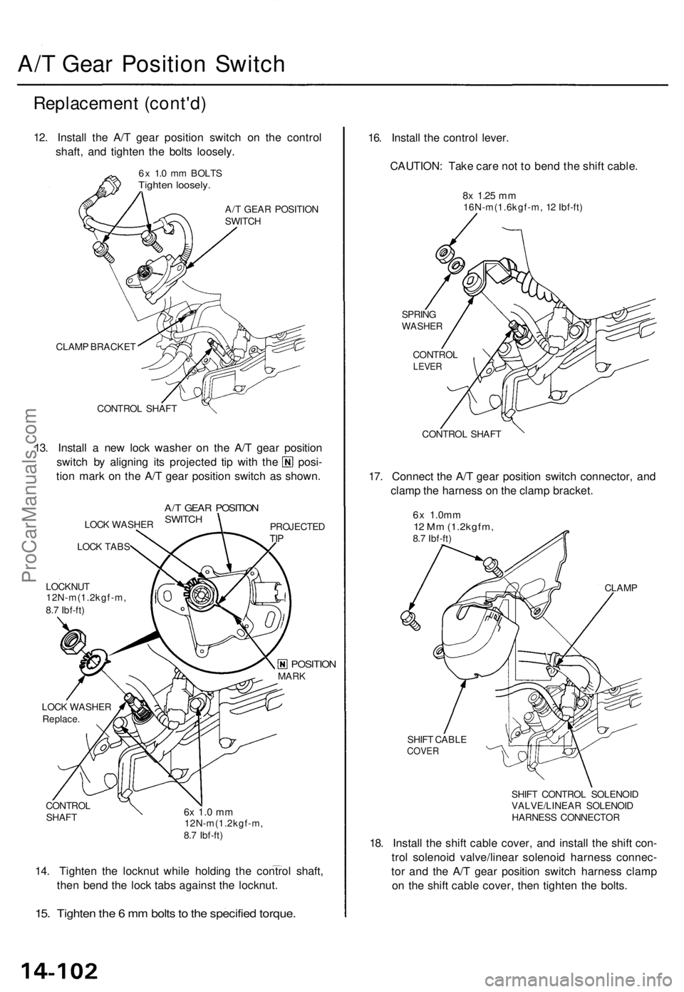
12. Instal l th e A/ T gea r positio n switc h o n th e contro l
shaft , an d tighte n th e bolt s loosely .
6x 1. 0 m m BOLT STighten loosely .
A/T GEA R POSITIO N
SWITC H
CLAM P BRACKE T
CONTRO L SHAF T
13. Instal l a ne w loc k washe r o n th e A/ T gea r positio n
switch b y alignin g it s projecte d ti p wit h th e posi -
tio n mar k o n th e A/ T gea r positio n switc h a s shown .
LOCK WASHE R
LOC K TAB S
LOCKNU T
12N-m(1.2kgf-m ,
8. 7 Ibf-ft )
A/T GEA R POSITIO NSWITCHPROJECTE DTIP
LOC K WASHE RReplace.
CONTRO L
SHAF T6x 1. 0 m m12N-m(1.2kgf-m ,
8. 7 Ibf-ft )
14. Tighte n th e locknu t whil e holdin g th e contro l shaft ,
the n ben d th e loc k tab s agains t th e locknut .
15. Tighte n th e 6 m m bolt s to th e specifie d torque .
16. Instal l th e contro l lever .
CAUTION : Tak e car e no t t o ben d th e shif t cable .
8x 1.2 5 mm16N-m(1.6kgf-m , 1 2 Ibf-ft )
SPRIN G
WASHE R
CONTRO LLEVER
CONTRO L SHAF T
17. Connec t th e A/ T gea r positio n switc h connector , an d
clam p th e harnes s o n th e clam p bracket .
6x 1.0m m12 M m (1.2kgfm ,8.7 Ibf-ft )
CLAMP
SHIF T CABL E
COVER
SHIFT CONTRO L SOLENOI D
VALVE/LINEA R SOLENOI D
HARNES S CONNECTO R
18. Instal l th e shif t cabl e cover , an d instal l th e shif t con -
tro l solenoi d valve/linea r solenoi d harnes s connec -
to r an d th e A/ T gea r positio n switc h harnes s clam p
o n th e shif t cabl e cover , the n tighte n th e bolts .
MARKPOSITIO N
ProCarManuals.com