1995 ACURA TL lock
[x] Cancel search: lockPage 352 of 1771
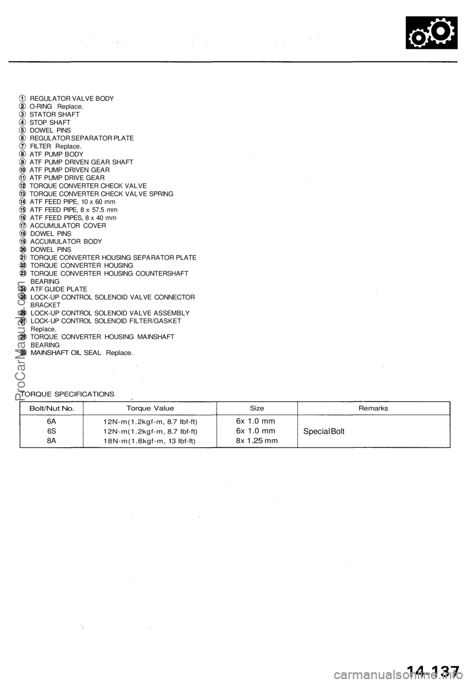
REGULATOR VALV E BOD Y
O-RIN G Replace .
STATO R SHAF T
STO P SHAF T
DOWE L PIN S
REGULATO R SEPARATO R PLAT E
FILTE R Replace .
AT F PUM P BOD Y
AT F PUM P DRIVE N GEA R SHAF T
AT F PUM P DRIVE N GEA R
AT F PUM P DRIV E GEA R
TORQU E CONVERTE R CHEC K VALV E
TORQU E CONVERTE R CHEC K VALV E SPRIN G
AT F FEE D PIPE , 1 0 x 60 m m
AT F FEE D PIPE , 8 x 57.5 m m
AT F FEE D PIPES , 8 x 40 m m
ACCUMULATO R COVE R
DOWE L PIN S
ACCUMULATO R BOD Y
DOWE L PIN S
TORQU E CONVERTE R HOUSIN G SEPARATO R PLAT E
TORQU E CONVERTE R HOUSIN G
TORQU E CONVERTE R HOUSIN G COUNTERSHAF T
BEARIN G
AT F GUID E PLAT E
LOCK-U P CONTRO L SOLENOI D VALV E CONNECTO R
BRACKETLOCK-UP CONTRO L SOLENOI D VALV E ASSEMBL Y
LOCK-U P CONTRO L SOLENOI D FILTER/GASKE T
Replace.TORQUE CONVERTE R HOUSIN G MAINSHAF TBEARINGMAINSHAF T OI L SEA L Replace .
TORQUE SPECIFICATION S
Bolt/Nut No .
6A
6S
8 A
Torqu e Valu e
12N-m(1.2kgf-m , 8. 7 Ibf-ft )
12N-m(1.2kgf-m , 8. 7 Ibf-ft )
18N-m(1.8kgf-m , 1 3 Ibf-ft ) Siz
e6x 1. 0 m m
6x 1. 0 m m
8x 1.2 5 mm
Remark s
Special Bol t
ProCarManuals.com
Page 355 of 1771
Rear Cove r
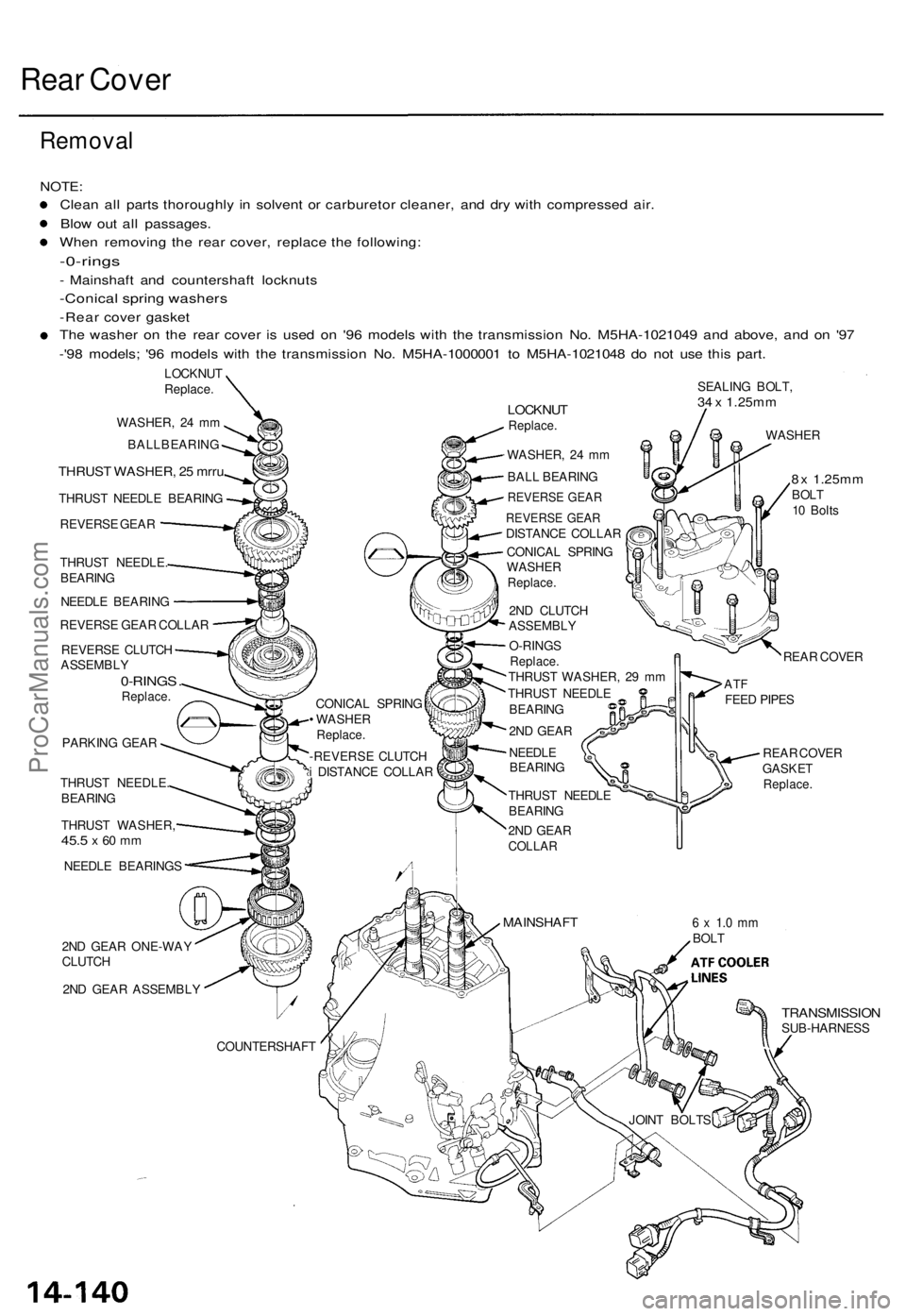
Remova l
NOTE:
Clean al l part s thoroughl y i n solven t o r carbureto r cleaner , an d dr y wit h compresse d air .
Blo w ou t al l passages .
Whe n removin g th e rea r cover , replac e th e following :
-0-rings
- Mainshaf t an d countershaf t locknut s
-Conical sprin g washer s
-Rear cove r gaske t
Th e washe r o n th e rea r cove r i s use d o n '9 6 model s wit h th e transmissio n No . M5H A-102104 9 an d above , an d o n '9 7
- '9 8 models ; '9 6 model s wit h th e transmissio n No . M5H A-100000 1 t o M5H A-102104 8 d o no t us e thi s part .
LOCKNU T
Replace .
WASHER , 2 4 m m
BALLBEARIN G
THRUST WASHER , 2 5 mrr u
THRUS T NEEDL E BEARIN G
REVERS E GEA R
THRUS T NEEDLE .
BEARIN G
NEEDL E BEARIN G
REVERS E GEA R COLLA R
REVERS E CLUTC H
ASSEMBL Y
0-RINGS .Replace .
PARKING GEA R
THRUS T NEEDLE .
BEARIN G
THRUS T WASHER ,
45.5 x 60 m m
NEEDL E BEARING S
2N D GEA R ONE-WA Y
CLUTC H
2N D GEA R ASSEMBL Y CONICA
L SPRIN G
• WASHE R
Replace.
-REVERS E CLUTC H
i DISTANC E COLLA R
LOCKNU TReplace.
WASHER , 2 4 m m
BAL L BEARIN G
REVERS E GEA R
REVERS E GEA RDISTANC E COLLA R
CONICA L SPRIN G
WASHE R
Replace .
2ND CLUTC H
ASSEMBL Y
O-RING S
Replace .THRUST WASHER , 2 9 m m
THRUS T NEEDL E
BEARIN G
2N D GEA R
NEEDL E
BEARIN G
THRUS T NEEDL E
BEARIN G
2N D GEA R
COLLA R
SEALIN G BOLT ,34 x 1.25m m
WASHE R
8x 1.25m mBOLT
1 0 Bolt s
REA R COVE R
ATFFEE D PIPE S
6 x 1. 0 m mBOL T
COUNTERSHAF T
TRANSMISSIONSUB-HARNESS
MAINSHAFT
JOINT BOLT S REA
R COVE R
GASKE T
Replace .
ProCarManuals.com
Page 356 of 1771
SNAP RIN GPLIER S
SNAP RIN G
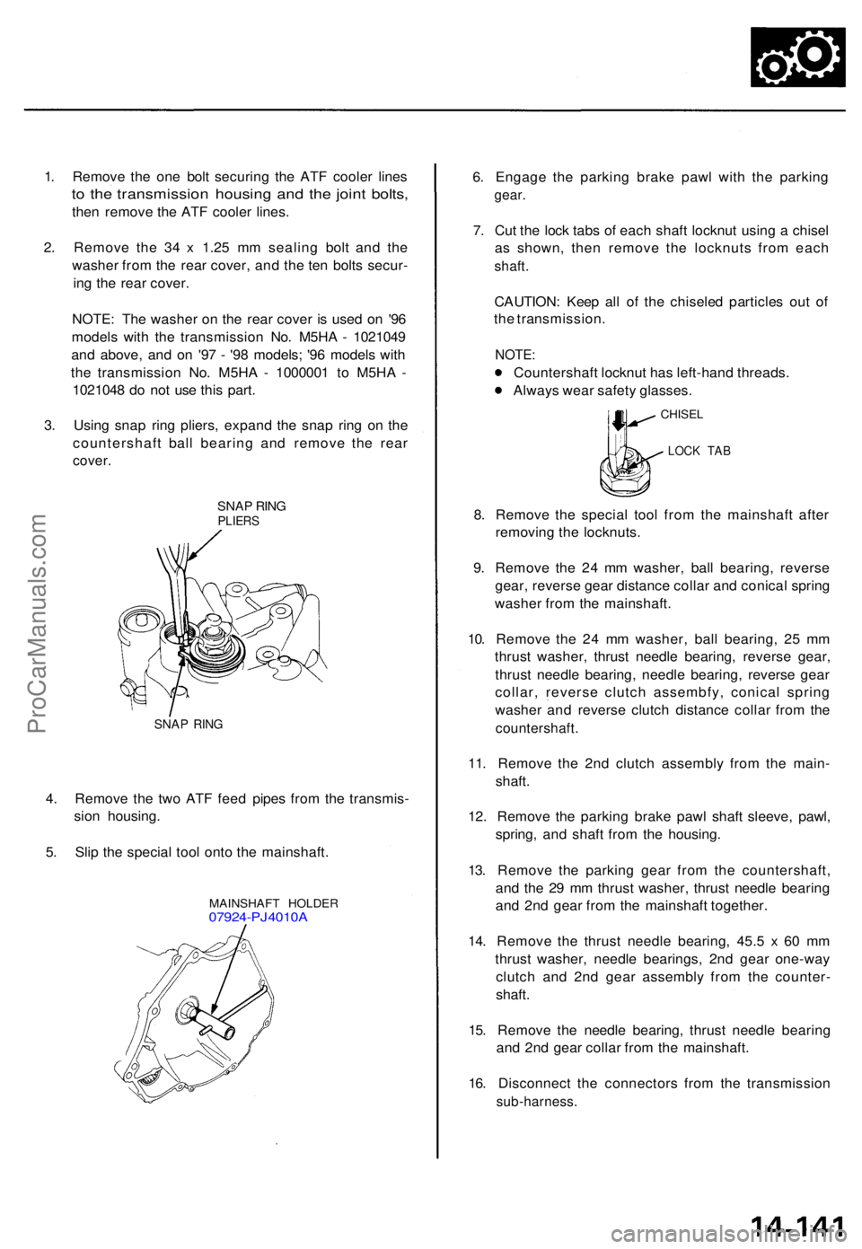
4. Remov e th e tw o AT F fee d pipe s fro m th e transmis -
sio n housing .
5 . Sli p th e specia l too l ont o th e mainshaft .
MAINSHAF T HOLDE R07924-PJ4010 A
6. Engag e th e parkin g brak e paw l wit h th e parkin g
gear.
7. Cu t th e loc k tab s o f eac h shaf t locknu t usin g a chise l
a s shown , the n remov e th e locknut s fro m eac h
shaft.
CAUTION : Kee p al l o f th e chisele d particle s ou t o f
th e transmission .
NOTE:
Countershaf t locknu t ha s left-han d threads .
Alway s wea r safet y glasses .
CHISEL
LOCK TA B
8. Remov e th e specia l too l fro m th e mainshaf t afte r
removin g th e locknuts .
9 . Remov e th e 2 4 m m washer , bal l bearing , revers e
gear , revers e gea r distanc e colla r an d conica l sprin g
washe r fro m th e mainshaft .
10 . Remov e th e 2 4 m m washer , bal l bearing , 2 5 m m
thrus t washer , thrus t needl e bearing , revers e gear ,
thrus t needl e bearing , needl e bearing , revers e gea r
collar , revers e clutc h assembfy , conica l sprin g
washe r an d revers e clutc h distanc e colla r fro m th e
countershaft .
11. Remov e th e 2n d clutc h assembl y fro m th e main -
shaft .
12 . Remov e th e parkin g brak e paw l shaf t sleeve , pawl ,
spring , an d shaf t fro m th e housing .
13 . Remov e th e parkin g gea r fro m th e countershaft ,
an d th e 2 9 m m thrus t washer , thrus t needl e bearin g
an d 2n d gea r fro m th e mainshaf t together .
14 . Remov e th e thrus t needl e bearing , 45. 5 x 6 0 m m
thrus t washer , needl e bearings , 2n d gea r one-wa y
clutc h an d 2n d gea r assembl y fro m th e counter -
shaft .
15 . Remov e th e needl e bearing , thrus t needl e bearin g
an d 2n d gea r colla r fro m th e mainshaft .
16 . Disconnec t th e connector s fro m th e transmissio n
sub-harness.
1. Remov e th e on e bol t securin g th e AT F coole r line s
to th e transmissio n housin g an d th e join t bolts ,
then remov e th e AT F coole r lines .
2 . Remov e th e 3 4 x 1.2 5 m m sealin g bol t an d th e
washe r fro m th e rea r cover , an d th e te n bolt s secur -
in g th e rea r cover .
NOTE : Th e washe r o n th e rea r cove r i s use d o n '9 6
model s wit h th e transmissio n No . M5H A - 102104 9
an d above , an d o n '9 7 - '9 8 models ; '9 6 model s wit h
th e transmissio n No . M5H A - 100000 1 t o M5H A -
102104 8 d o no t us e thi s part .
3 . Usin g sna p rin g pliers , expan d th e sna p rin g o n th e
countershaf t bal l bearin g an d remov e th e rea r
cover .
ProCarManuals.com
Page 371 of 1771
Regulator Valv e Bod y — '96 Mode l
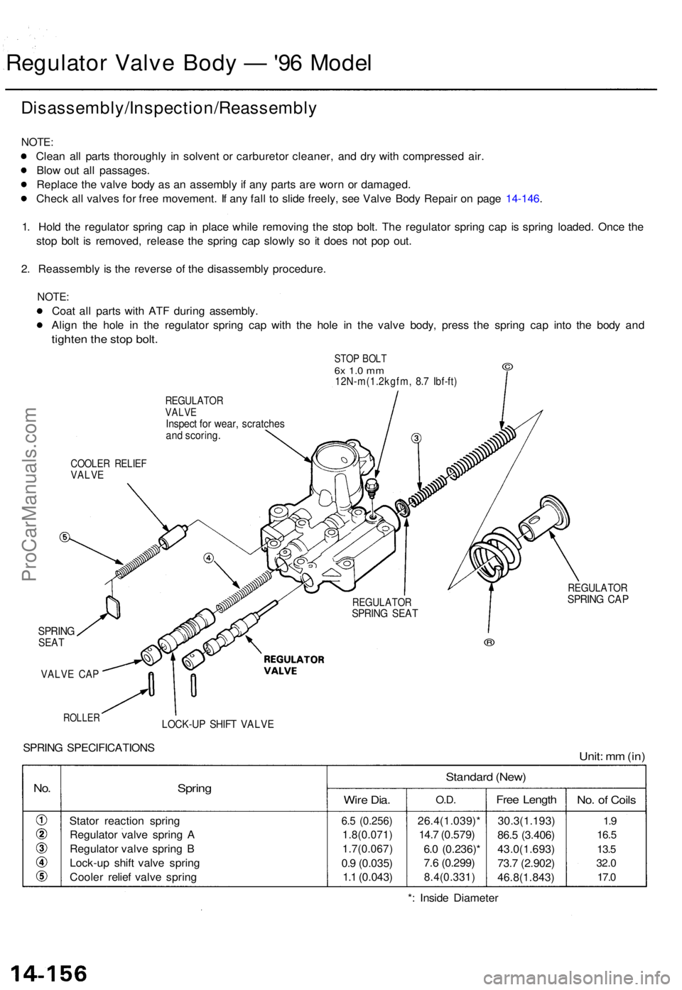
Disassembly/Inspection/Reassembl y
NOTE:
Clean al l part s thoroughl y i n solven t o r carbureto r cleaner , an d dr y wit h compresse d air .
Blo w ou t al l passages .
Replac e th e valv e bod y a s a n assembl y i f an y part s ar e wor n o r damaged .
Chec k al l valve s fo r fre e movement . I f an y fal l t o slid e freely , se e Valv e Bod y Repai r o n pag e 14-146 .
1 . Hol d th e regulato r sprin g ca p i n plac e whil e removin g th e sto p bolt . Th e regulato r sprin g ca p i s sprin g loaded . Onc e th e
sto p bol t i s removed , releas e th e sprin g ca p slowl y s o i t doe s no t po p out .
2 . Reassembl y i s th e revers e o f th e disassembl y procedure .
NOTE:
Coat al l part s wit h AT F durin g assembly .
Alig n th e hol e i n th e regulato r sprin g ca p wit h th e hol e i n th e valv e body , pres s th e sprin g ca p int o th e bod y an d
tighte n th e sto p bolt .
STO P BOL T6x 1. 0 m m12N-m(1.2kgfm , 8. 7 Ibf-ft )
©
REGULATO RVALVEInspec t fo r wear , scratche sand scoring .
COOLER RELIE FVALVE
REGULATO RSPRING SEA T
REGULATO RSPRING CA P
SPRIN GSEAT
VALV E CA P
ROLLE R
®
LOCK-U P SHIF T VALV E
SPRING SPECIFICATION SUnit: m m (in )
No.Sprin g
Stato r reactio n sprin g
Regulato r valv e sprin g A
Regulato r valv e sprin g B
Lock-u p shif t valv e sprin g
Coole r relie f valv e sprin g
Standar d (New )
Wire Dia .
6.5 (0.256 )
1.8(0.071 )
1.7(0.067)
0.9 (0.035 )
1. 1 (0.043 )
O.D.
26.4(1.039) *
14. 7 (0.579 )
6. 0 (0.236) *
7. 6 (0.299 )
8.4(0.331 )
Free Lengt h
30.3(1.193 )
86. 5 (3.406 )
43.0(1.693 )
73. 7 (2.902 )
46.8(1.843 )
No. o f Coil s
1.9
16. 5
13. 5
32. 0
17. 0
*: Insid e Diamete r
ProCarManuals.com
Page 372 of 1771
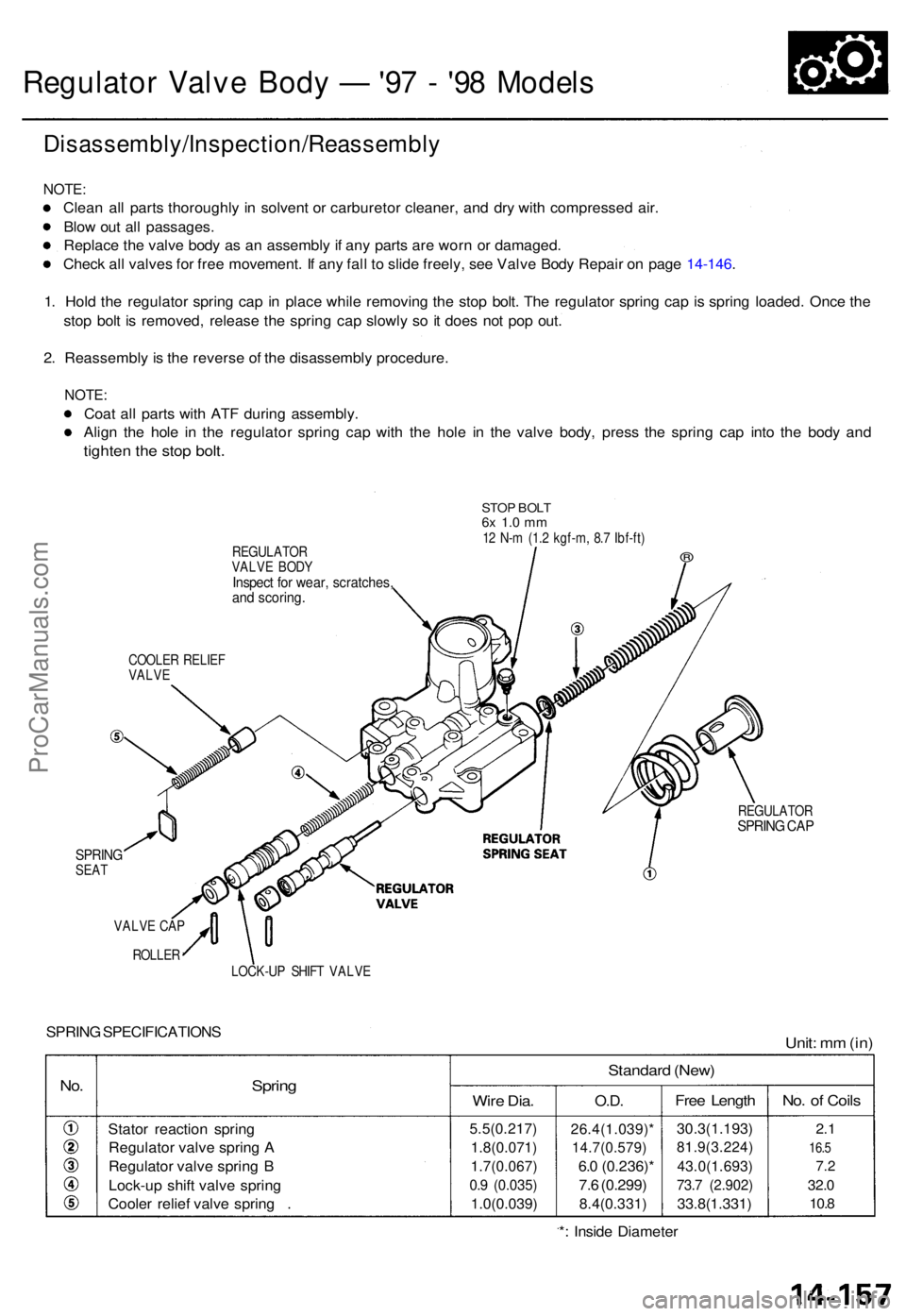
Regulator Valv e Bod y — '97 - '9 8 Model s
Disassembly/Inspection/Reassembl y
NOTE:
Clean al l part s thoroughl y i n solven t o r carbureto r cleaner , an d dr y wit h compresse d air .
Blo w ou t al l passages .
Replac e th e valv e bod y a s a n assembl y if an y part s ar e wor n o r damaged .
Chec k al l valve s fo r fre e movement . I f an y fal l t o slid e freely , se e Valv e Bod y Repai r o n pag e 14-146 .
1 . Hol d th e regulato r sprin g ca p in plac e whil e removin g th e sto p bolt . Th e regulato r sprin g ca p is sprin g loaded . Onc e th e
sto p bol t i s removed , releas e th e sprin g ca p slowl y s o it doe s no t po p out .
2 . Reassembl y i s th e revers e o f th e disassembl y procedure .
NOTE:
Coat al l part s wit h AT F during assembly .
Alig n th e hol e i n th e regulato r sprin g ca p wit h th e hol e i n th e valv e body , pres s th e sprin g ca p int o th e bod y an d
tighte n th e sto p bolt .
REGULATO R
VALV E BOD Y
Inspec t fo r wear , scratches ,and scoring .
STOP BOL T6x 1. 0 m m12 N- m (1. 2 kgf-m , 8. 7 Ibf-ft )
®
COOLE R RELIE F
VALV E
SPRIN GSEAT
VALV E CA P
ROLLE R
REGULATO RSPRING CA P
LOCK-U P SHIF T VALV E
SPRING SPECIFICATION SUnit: m m (in )
No.Sprin g
Stato r reactio n sprin g
Regulato r valv e sprin g A
Regulato r valv e sprin g B
Lock-u p shif t valv e sprin g
Coole r relie f valv e sprin g .
Standar d (New )
Wire Dia .
5.5(0.217 )
1.8(0.071)
1.7(0.067 )
0.9 (0.035 )
1.0(0.039 )
O.D.
26.4(1.039) *
14.7(0.579)
6.0 (0.236) *
7. 6 (0.299 )
8.4(0.331 )
Free Lengt h
30.3(1.193 )
81.9(3.224 )
43.0(1.693)
73.7 (2.902 )
33.8(1.331 )
No. o f Coil s
2.1
16. 5
7.2
32. 0
10. 8
*: Insid e Diamete r
ProCarManuals.com
Page 375 of 1771
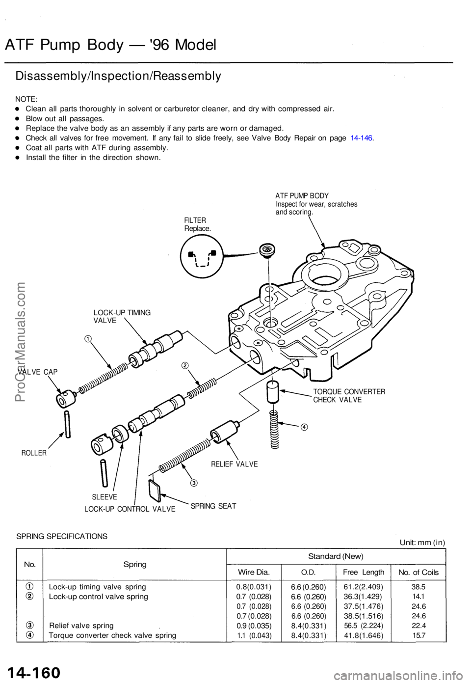
ATF Pum p Bod y — '96 Mode l
Disassembly/Inspection/Reassembl y
NOTE:
Clean al l part s thoroughl y i n solven t o r carbureto r cleaner , an d dr y wit h compresse d air .
Blo w ou t al l passages .
Replac e th e valv e bod y a s a n assembl y if an y part s ar e wor n o r damaged .
Chec k al l valve s fo r fre e movement . I f an y fai l t o slid e freely , se e Valv e Bod y Repai r o n pag e 14-146 .
Coa t al l part s wit h AT F durin g assembly .
Instal l th e filte r i n th e directio n shown .
FILTERReplace .
LOCK-U P TIMIN GVALVE
VALV E CA P
ROLLE R
TORQU E CONVERTE RCHECK VALV E
SPRING SPECIFICATION SUnit: m m (in )
No.Sprin g
Lock-u p timin g valv e sprin g
Lock-u p contro l valv e sprin g
Relief valv e sprin g
Torqu e converte r chec k valv e sprin g
Standar d (New )
Wire Dia .
0.8(0.031 )
0.7 (0.028 )
0.7 (0.028 )
0.7 (0.028 )
0. 9 (0.035 )
1.1 (0.043 )
O.D.
6.6 (0.260 )
6. 6 (0.260 )
6.6 (0.260 )
6. 6 (0.260 )
8.4(0.331 )
8.4(0.331 )
Free Lengt h
61.2(2.409 )
36.3(1.429)
37.5(1.476 )
38.5(1.516)
56.5 (2.224 )
41.8(1.646 )
No. o f Coil s
38.5
14. 1
24. 6
24. 6
22. 4
15.7
RELIE F VALV E
SLEEV E
SPRING SEA TLOCK-U P CONTRO L VALV E
ATF PUM P BOD YInspec t fo r wear , scratche sand scoring .
ProCarManuals.com
Page 376 of 1771
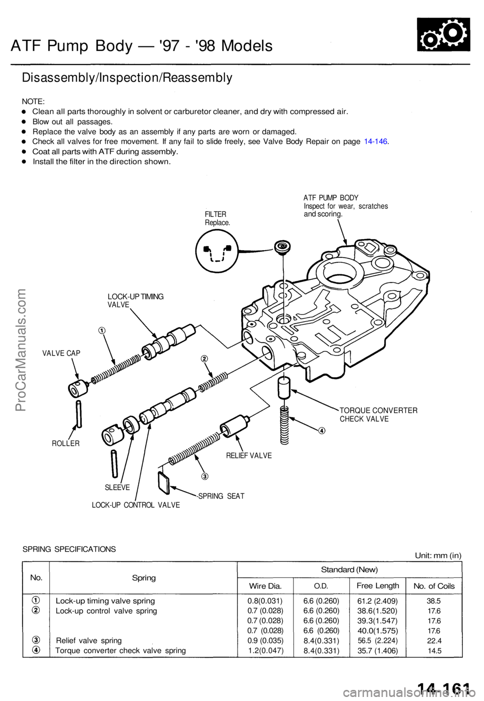
ATF Pum p Bod y — '97 - '9 8 Model s
Disassembly/Inspection/Reassembl y
NOTE:
Clean al l part s thoroughl y in solven t o r carbureto r cleaner , an d dr y wit h compresse d air .
Blow ou t al l passages .
Replac e th e valv e bod y a s a n assembl y i f an y part s ar e wor n o r damaged .
Chec k al l valve s fo r fre e movement . I f an y fai l t o slid e freely , se e Valv e Bod y Repai r o n pag e 14-146 .
Coat al l part s wit h AT F durin g assembly .
Install th e filte r i n th e directio n shown .
FILTER
Replace . AT
F PUM P BOD Y
Inspec t fo r wear , scratche sand scoring .
TORQUE CONVERTERCHECK VALVE
ROLLE R
SLEEVE
LOCK-U P CONTRO L VALV E -SPRIN
G SEA T
SPRIN G SPECIFICATION SUnit: m m (in )
No.Sprin g
Lock-u p timin g valv e sprin g
Lock-u p contro l valv e sprin g
Relie f valv e sprin g
Torqu e converte r chec k valv e sprin g
Standar d (New )
Wire Dia .
0.8(0.031 )
0. 7 (0.028 )
0. 7 (0.028 )
0. 7 (0.028 )
0. 9 (0.035 )
1.2(0.047 )
O.D.
6.6 (0.260 )
6. 6 (0.260 )
6. 6 (0.260 )
6. 6 (0.260 )
8.4(0.331 )
8.4(0.331 )
Free Lengt h
61.2 (2.409 )
38.6(1.520 )
39.3(1.547 )
40.0(1.575)
56.5 (2.224 )
35.7 (1.406 )
No. o f Coil s
38.5
17. 6
17. 6
17. 6
22. 4
14. 5
VALV E CA P
RELIEF VALV E
LOCK-U P TIMIN GVALV E
ProCarManuals.com
Page 382 of 1771
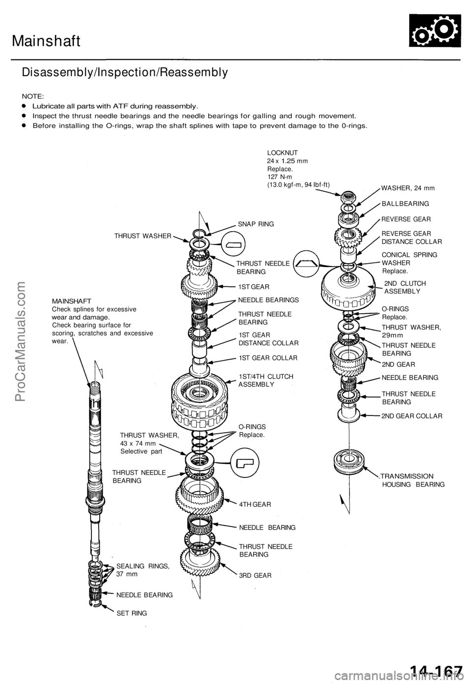
Mainshaft
Disassembly/Inspection/Reassembly
NOTE:
Lubricate all parts with ATF during reassembly.
Inspect the thrust needle bearings and the needle bearings for galling and rough movement.
Before installing the O-rings, wrap the shaft splines with tape to prevent damage to the 0-rings.
THRUST WASHER
MAINSHAFT
Check splines for excessive
wear and damage.
Check bearing surface for
scoring, scratches and excessive
wear.
h
THRUST WASHER,
43 x 74 mm
Selective part
THRUST NEEDLE
BEARING
SEALING RINGS,
37 mm
NEEDLE BEARING
SET RING
LOCKNUT
24 x
1.25
mm
Replace.
127 N-m
(13.0 kgf-m, 94 Ibf-ft)
SNAP RING
THRUST NEEDLE
BEARING
1ST GEAR
NEEDLE BEARINGS
THRUST NEEDLE
BEARING
1ST GEAR
DISTANCE COLLAR
1ST GEAR COLLAR
1ST/4TH CLUTCH
ASSEMBLY
O-RINGS
Replace.
4TH GEAR
NEEDLE BEARING
THRUST NEEDLE
BEARING
3RD GEAR
WASHER, 24 mm
BALLBEARING
REVERSE GEAR
REVERSE GEAR
DISTANCE COLLAR
CONICAL SPRING
WASHER
Replace.
2ND CLUTCH
ASSEMBLY
O-RINGS
Replace.
THRUST WASHER,
29mm
THRUST NEEDLE
BEARING
2ND GEAR
NEEDLE BEARING
THRUST NEEDLE
BEARING
2ND GEAR COLLAR
.TRANSMISSION
HOUSING BEARINGProCarManuals.com