1995 ACURA TL lock
[x] Cancel search: lockPage 448 of 1771
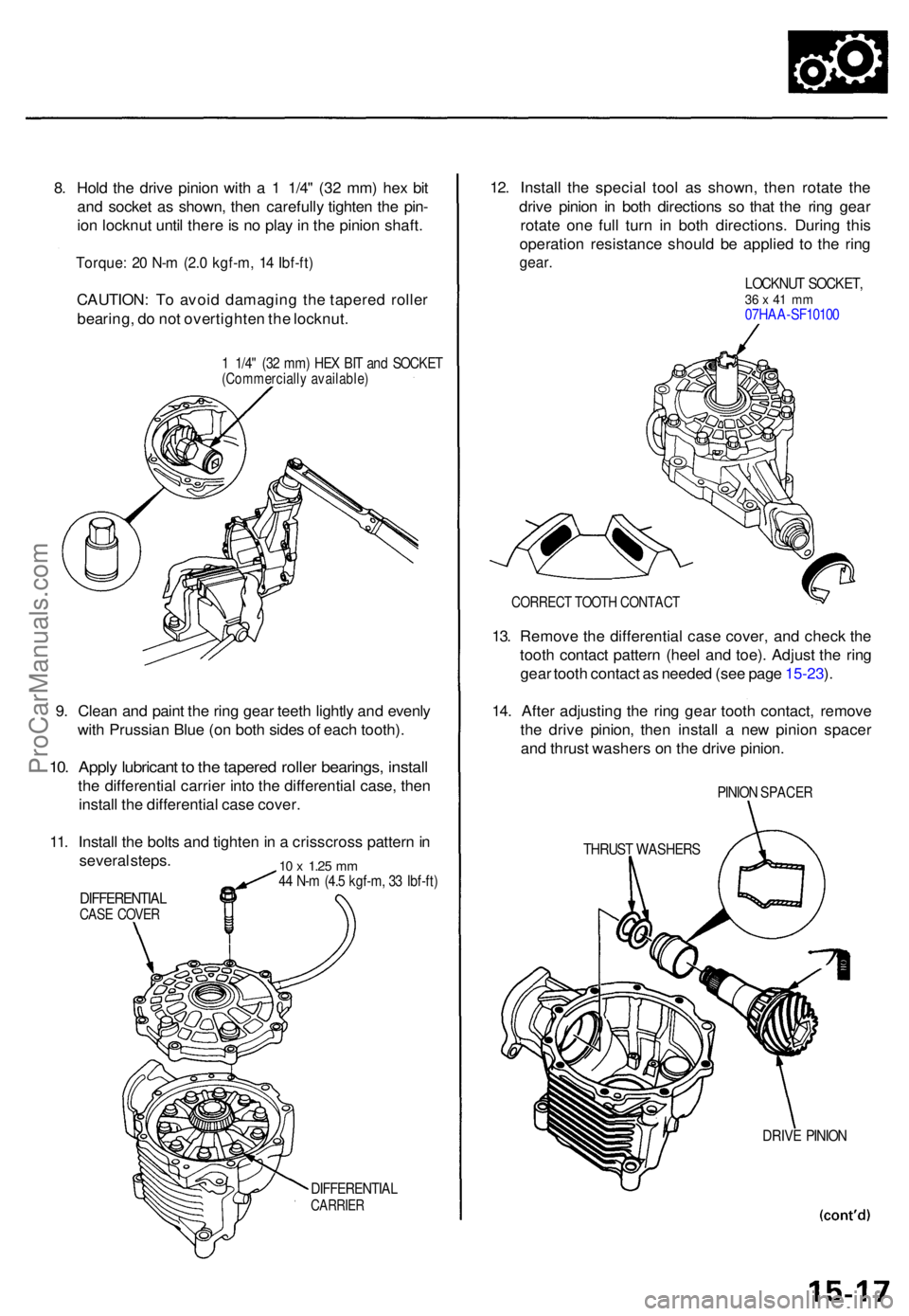
8. Hol d th e driv e pinio n wit h a 1 1/4 " (3 2 mm ) he x bi t
an d socke t a s shown , the n carefull y tighte n th e pin -
io n locknu t unti l ther e is n o pla y in th e pinio n shaft .
Torque : 2 0 N- m (2. 0 kgf-m , 1 4 Ibf-ft )
CAUTION : T o avoi d damagin g th e tapere d rolle r
bearing , d o no t overtighte n th e locknut .
1 1/4 " (3 2 mm ) HE X BI T an d SOCKE T(Commerciall y available )
9. Clea n an d pain t th e rin g gea r teet h lightl y an d evenl y
wit h Prussia n Blu e (o n bot h side s o f eac h tooth) .
10. Appl y lubrican t t o th e tapere d rolle r bearings , instal l
the differentia l carrie r int o th e differentia l case , the n
instal l th e differentia l cas e cover .
11 . Instal l th e bolt s an d tighte n in a crisscros s patter n in
severa l steps .
DIFFERENTIA LCASE COVE R
10 x 1.2 5 mm44 N- m (4. 5 kgf-m , 3 3 Ibf-ft )
DIFFERENTIA LCARRIER
12. Instal l th e specia l too l a s shown , the n rotat e th e
driv e pinio n i n bot h direction s s o tha t th e rin g gea r
rotat e on e ful l tur n i n bot h directions . Durin g thi s
operation resistanc e shoul d b e applie d t o th e rin g
gear .
LOCKNU T SOCKET ,36 x 41 m m07HA A-SF1010 0
CORREC T TOOT H CONTAC T
13. Remov e th e differentia l cas e cover , an d chec k th e
toot h contac t patter n (hee l an d toe) . Adjus t th e rin g
gea r toot h contac t a s neede d (se e pag e 15-23 ).
14 . Afte r adjustin g th e rin g gea r toot h contact , remov e
th e driv e pinion , the n instal l a ne w pinio n space r
an d thrus t washer s o n th e driv e pinion .
PINION SPACE R
THRUST WASHER S
DRIVE PINIO N
ProCarManuals.com
Page 449 of 1771
Differential Assembl y
Reassembl y (cont'd )
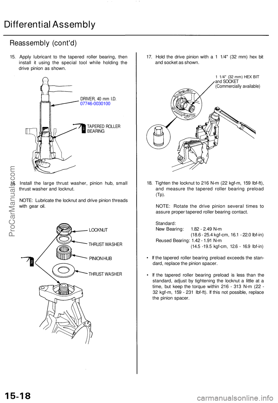
15. Appl y lubrican t t o th e tapere d rolle r bearing , the n
instal l i t usin g th e specia l too l whil e holdin g th e
driv e pinio n a s shown .
DRIVER , 4 0 m m I.D .07746-003010 0
TAPERED ROLLE RBEARIN G
16. Instal l th e larg e thrus t washer , pinio n hub , smal l
thrus t washe r an d locknut .
NOTE : Lubricat e th e locknu t an d driv e pinio n thread s
wit h gea r oil . 17
. Hol d th e driv e pinio n wit h a 1 1/4 " (3 2 mm ) he x bi t
an d socke t a s shown .
1 1/4" (32 mm ) HE X BI Tand SOCKE T(Commerciall y available )
18. Tighte n th e locknu t t o 21 6 N- m (2 2 kgf-m , 15 9 Ibf-ft) ,
an d measur e th e tapere d rolle r bearin g preloa d
(Tp).
NOTE : Rotat e th e driv e pinio n severa l time s t o
assur e prope r tapere d rolle r bearin g contact .
Standard :
New Bearing : 1.8 2 - 2.4 9 N- m
(18. 6 - 25. 4 kgf-cm , 16. 1 - 22. 0 Ibf-in )
Reuse d Bearing : 1.4 2 - 1.9 1 N- m
(14. 5 -19. 5 kgf-cm , 12. 6 - 16. 9 Ibf-in )
• I f th e tapere d rolle r bearin g preloa d exceed s th e stan -
dard , replac e th e pinio n spacer .
• I f th e tapere d rolle r bearin g preloa d i s les s tha n th e
standard , adjus t b y tightenin g th e locknu t a littl e a t a
time , bu t kee p th e torqu e withi n 21 6 - 31 3 N- m (2 2 -
3 2 kgf-m , 15 9 - 23 1 Ibf-ft) . I f thi s no t possible , replac e
th e pinio n spacer .
LOCKNU T
THRUST WASHE R
PINION HU B
THRUS T WASHE R
ProCarManuals.com
Page 450 of 1771
19. Clea n an d pain t th e rin g gea r teet h lightl y an d evenl y
wit h Prussia n Blu e (o n bot h side s o f eac h tooth) .
20 . Instal l th e differentia l carrie r int o th e differentia l
case , an d reinstal l th e differential case cover .
21 . Instal l th e bolt s an d tighte n i n a crisscros s patter n in
severa l steps .
Torque : 4 4 N- m (4. 5 kgf-m , 3 3 Ibf-ft )
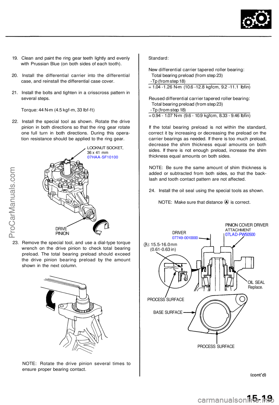
22 . Instal l th e specia l too l a s shown . Rotat e th e driv e
pinio n i n bot h direction s s o tha t th e rin g gea r rotat e
on e ful l tur n i n bot h directions . Durin g thi s opera -
tio n resistanc e shoul d b e applie d t o th e rin g gear .
LOCKNU T SOCKET ,36 x 41 m m07HAA-SF10100
DRIV EPINIO N
23. Remov e th e specia l tool , an d us e a dial-typ e torqu e
wrenc h o n th e driv e pinio n t o chec k tota l bearin g
preload . Th e tota l bearin g preloa d shoul d excee d
th e driv e pinio n bearin g preloa d b y th e amoun t
show n i n th e nex t column .
NOTE : Rotat e th e driv e pinio n severa l time s t o
ensur e prope r bearin g contact .
Standard :
New differentia l carrie r tapere d rolle r bearing :
Tota l bearin g preloa d (fro m ste p 23 )
-Tp (fro m ste p 18 )
= 1.0 4 -1.2 6 N- m (10. 6 -12. 8 kgfcm , 9. 2 -11. 1 Ibfin )
Reuse d differentia l carrie r tapere d rolle r bearing :
Tota l bearin g preloa d (fro m ste p 23 )
- T p (fro m ste p 18 )
= 0.9 4 - 1.0 7 N- m (9. 6 - 10. 9 kgfcm , 8.3 3 - 9.4 6 Ibfin )
I f th e tota l bearin g preloa d i s no t withi n th e standard ,
correc t i t b y increasin g o r decreasin g th e preloa d o n th e
carrie r bearing s a s needed . I f ther e i s to o muc h preload ,
decreas e th e shi m thicknes s equa l amount s o n bot h
sides . I f ther e i s no t enoug h preload , increase the shi m
thicknes s equa l amount s o n bot h sides .
NOTE : B e sur e th e sam e amoun t of shi m thicknes s i s
adde d o r subtracte d fro m bot h sides , s o tha t th e back -
las h an d toot h contac t patter n ar e no t affected .
24 . Instal l th e oi l sea l usin g th e specia l tool s a s shown .
NOTE: Mak e sur e tha t distanc e i s correct .
DRIVER07749-001000 0
PINION COVE R DRIVE RATTACHMEN T07LAD-PW5050 0
(A): 15.5-16. 0 mm(0.61-0.6 3 in )
OIL SEA L
Replace .
PROCES S SURFAC E
BAS E SURFAC E
PROCESS SURFAC E
ProCarManuals.com
Page 451 of 1771
Differential Assembl y
Reassembl y (cont'd )
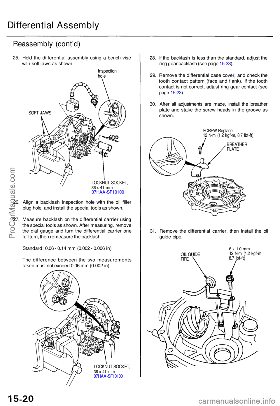
25. Hol d th e differentia l assembl y usin g a benc h vis e
wit h sof t jaw s a s shown .
Inspectio nhole
SOF T JAW S
LOCKNUT SOCKET ,
36 x 41 m m07HAA-SF1010 0
26. Alig n a backlas h inspectio n hol e wit h th e oi l fille r
plu g hole , an d instal l th e specia l tool s a s shown .
27 . Measur e backlas h o n th e differentia l carrie r usin g
th e specia l tool s a s shown . Afte r measuring , remov e
th e dia l gaug e an d tur n th e differentia l carrie r on e
ful l turn , the n remeasur e th e backlash .
Standard : 0.0 6 - 0.1 4 m m (0.00 2 - 0.00 6 in )
Th e differenc e betwee n th e tw o measurement s
take n mus t no t excee d 0.0 6 m m (0.00 2 in) .
LOCKNU T SOCKET ,36 x 41 m m07HA A-SF1010 0
28. I f th e backlas h i s les s tha n th e standard , adjus t th e
rin g gea r backlas h (se e pag e 15-23 ).
29 . Remov e th e differentia l cas e cover , an d chec k th e
toot h contac t patter n (fac e an d flank) . I f th e toot h
contac t i s no t correct , adjus t rin g gea r contac t (se e
page 15-23 ).
30 . Afte r al l adjustment s ar e made , instal l th e breathe r
plat e an d stak e th e scre w head s i n th e groov e a s
shown .
SCREW Replace .
1 2 N- m (1. 2 kgf-m , 8. 7 Ibf-ft )
BREATHE RPLATE
31. Remov e th e differentia l carrier , the n instal l th e oi l
guid e pipe .
OIL GUID EPIPE
6 x 1. 0 m m12 N- m (1. 2 kgf-m ,
8. 7 Ibf-ft )
ProCarManuals.com
Page 452 of 1771
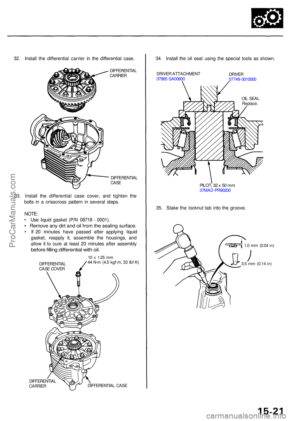
32. Instal l th e differentia l carrie r i n th e differentia l case .
DIFFERENTIA LCARRIER
DIFFERENTIA LCASE
DIFFERENTIA LCARRIERDIFFERENTIA L CAS E
34. Instal l th e oi l sea l usin g th e specia l tool s a s shown .
DRIVER ATTACHMEN T
0796 5-SA0060 0DRIVER07749-001000 0
OI L SEA L
Replace .
PILOT, 3 2 x 50 m m07MA D-PR9020 0
35. Stak e th e locknu t ta b int o th e groove .
1.0 m m (0.0 4 in)
33. Instal l th e differentia l cas e cover , an d tighte n th e
bolt s i n a crisscros s patter n i n severa l steps .
NOTE :
• Us e liqui d gaske t (P/ N 0871 8 - 0001) .
• Remov e an y dir t an d oi l fro m th e sealin g surface .
• I f 2 0 minute s hav e passe d afte r applyin g liqui d
gasket , reappl y it , assembl e th e housings , an d
allo w it t o cur e a t leas t 2 0 minute s afte r assembl y
before fillin g differentia l wit h oil .
10 x 1.2 5 mm44 N- m (4. 5 kgf-m , 3 3 Ibf-ft )
DIFFERENTIA L
CAS E COVE R3.5 m m (0.1 4 in)
ProCarManuals.com
Page 467 of 1771
Inspection an d Adjustmen t
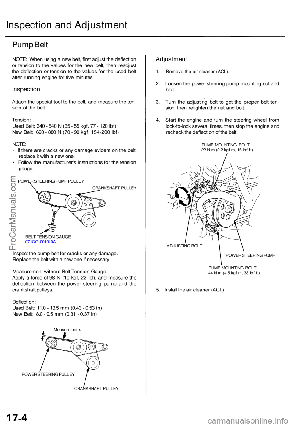
Pump Bel t
NOTE : Whe n usin g a ne w belt , firs t adjus t th e deflectio n
o r tensio n t o th e value s fo r th e ne w belt , the n readjus t
th e deflectio n o r tensio n t o th e value s fo r th e use d bel t
afte r runnin g engin e fo r fiv e minutes .
Inspectio n
Attach th e specia l too l t o th e belt , an d measur e th e ten -
sio n o f th e belt .
Tension :
Used Belt : 34 0 - 54 0 N (3 5 - 5 5 kgf , 7 7 - 12 0 Ibf )
Ne w Belt : 69 0 - 88 0 N (7 0 - 9 0 kgf , 154-20 0 Ibf )
NOTE :
• I f ther e ar e crack s o r an y damag e eviden t o n th e belt ,
replac e it wit h a ne w one .
• Follo w th e manufacturer' s instruction s fo r th e tensio n
gauge .
POWE R STEERIN G PUM P PULLE Y
CRANKSHAF T PULLE Y
BELT TENSIO N GAUG E
07JG G-001010 A
Inspect th e pum p bel t fo r crack s o r an y damage .
Replac e th e bel t wit h a ne w on e if necessary .
Measuremen t withou t Bel t Tensio n Gauge :
Appl y a forc e o f 9 8 N (1 0 kgf , 2 2 Ibf) , an d measur e th e
deflectio n betwee n th e powe r steerin g pum p an d th e
crankshaf t pulleys .
Deflection :
Use d Belt : 11. 0 - 13. 5 m m (0.4 3 - 0.5 3 in )
Ne w Belt : 8. 0 - 9. 5 m m (0.3 1 - 0.3 7 in )
Measur e her e
POWE R STEERIN G PULLE Y
CRANKSHAF T PULLE Y
Adjustmen t
1. Remov e th e ai r cleane r (ACL) .
2. Loose n th e powe r steerin g pum p mountin g nu t an d
bolt .
3. Tur n th e adjustin g bol t t o ge t th e prope r bel t ten -
sion , the n retighte n th e nu t an d bolt .
4 . Star t th e engin e an d tur n th e steerin g whee l fro m
lock-to-loc k severa l times , the n sto p th e engin e an d
rechec k th e deflectio n o f th e belt .
PUM P MOUNTIN G BOL T
2 2 N- m (2. 2 kgf-m , 1 6 Ibf-ft )
ADJUSTIN G BOL T
POWER STEERIN G PUM P
PUM P MOUNTIN G BOL T
44 N- m (4. 5 kgf-m , 3 3 Ibf-ft )
5. Instal l th e ai r cleane r (ACL) .
ProCarManuals.com
Page 468 of 1771
Rack Guide Adjustment
NOTE: Perform rack guide adjustment with the wheels
in the straight ahead position.
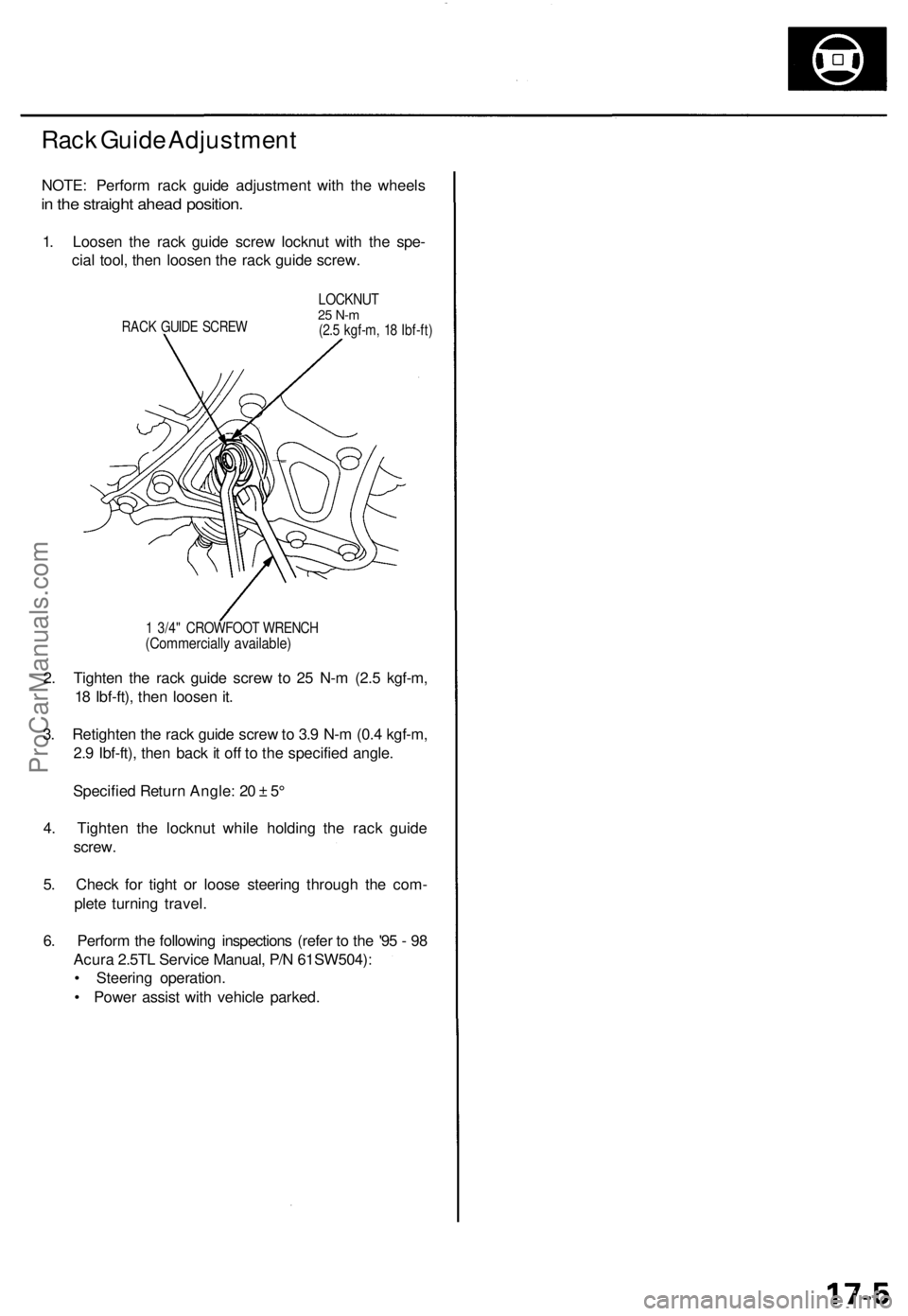
1. Loosen the rack guide screw locknut with the spe-
cial tool, then loosen the rack guide screw.
RACK GUIDE SCREW
LOCKNUT
25 N-m
(2.5 kgf-m, 18 Ibf-ft)
1 3/4" CROWFOOT WRENCH
(Commercially available)
2. Tighten the rack guide screw to 25 N-m (2.5 kgf-m,
18 Ibf-ft), then loosen it.
3. Retighten the rack guide screw to 3.9 N-m (0.4 kgf-m,
2.9 Ibf-ft), then back it off to the specified angle.
Specified Return Angle: 20 ± 5°
4. Tighten the locknut while holding the rack guide
screw.
5. Check for tight or loose steering through the com-
plete turning travel.
6. Perform the following inspections (refer to the '95 - 98
Acura 2.5TL Service Manual, P/N 61SW504):
• Steering operation.
• Power assist with vehicle parked.ProCarManuals.com
Page 470 of 1771
Inspection an d Adjustmen t
Pump Pressur e Chec k (cont'd )
7. Star t th e engin e an d le t i t idle .
8 . Tur n th e steerin g whee l fro m lock-to-loc k severa l
time s to war m th e flui d to operatin g temperature .
9 . Measur e steady-stat e flui d pressur e whil e idling . I f
th e pum p i s i n goo d condition , th e gaug e shoul d
rea d les s tha n 150 0 kP a (1 5 kgf/cm
2, 21 3 psi) .
I f i t read s high , chec k th e outle t hos e o r valv e bod y
uni t (refe r t o th e '9 5 - 9 8 Acur a 2.5T L Servic e
Manual , P/ N 61SW504 , fo r Genera l Troubleshoot -
ing).
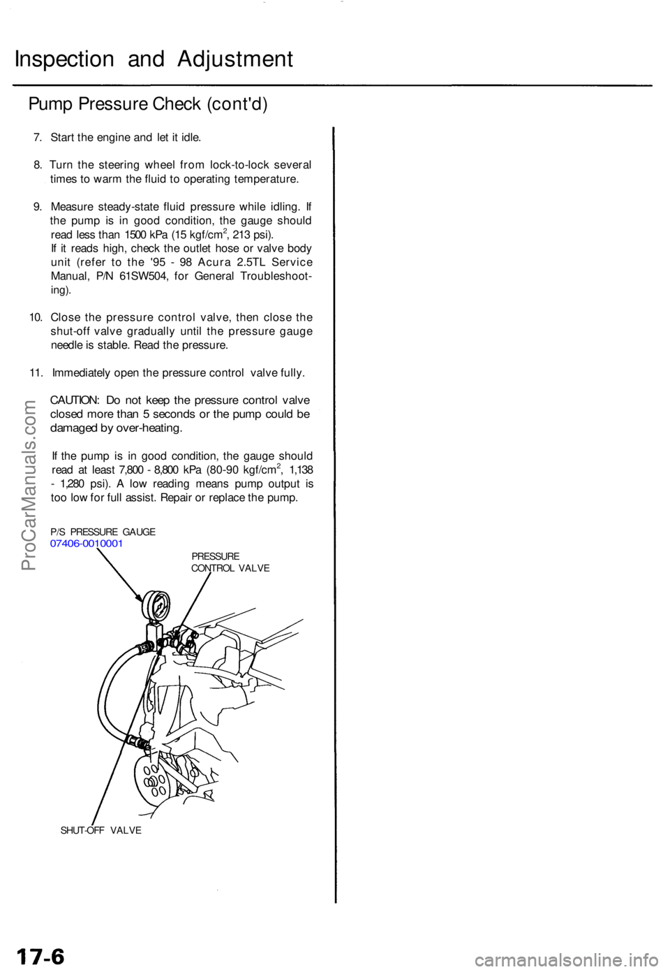
10. Clos e th e pressur e contro l valve , the n clos e th e
shut-of f valv e graduall y unti l th e pressur e gaug e
needl e is stable . Rea d th e pressure .
11 . Immediatel y ope n th e pressur e contro l valv e fully .
CAUTION : D o no t kee p th e pressur e contro l valv e
close d mor e tha n 5 second s o r th e pum p coul d b e
damage d b y over-heating .
If th e pum p i s i n goo d condition , th e gaug e shoul d
rea d a t leas t 7,80 0 - 8,80 0 kP a (80-9 0 kgf/cm2, 1,13 8
- 1,28 0 psi) . A lo w readin g mean s pum p outpu t i s
to o lo w fo r ful l assist . Repai r o r replac e th e pump .
SHUT-OF F VALV E
PRESSUR ECONTROL VALV E
P/
S PRESSUR E GAUG E
07406-001000 1
ProCarManuals.com