1995 ACURA TL lock
[x] Cancel search: lockPage 501 of 1771
Front Dampe r
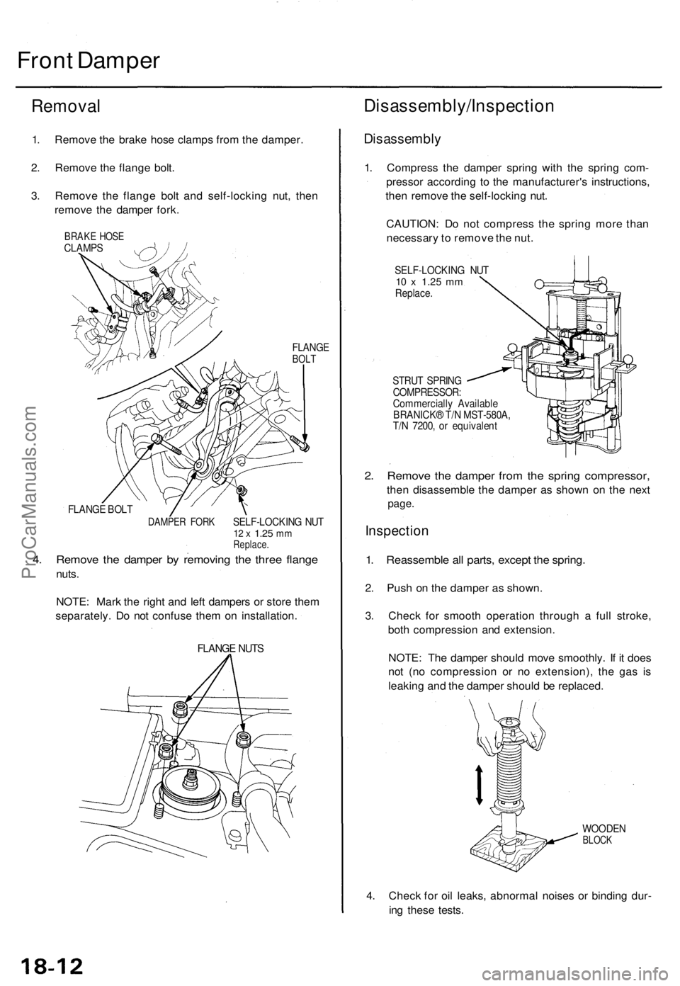
Remova l
1. Remov e th e brak e hos e clamp s fro m th e damper .
2 . Remov e th e flang e bolt .
3 . Remov e th e flang e bol t an d self-lockin g nut , the n
remov e th e dampe r fork .
BRAK E HOS ECLAMP S
FLANGEBOLT
SELF-LOCKIN G NU T12 x 1.2 5 mmReplace .
4. Remov e th e dampe r b y removin g th e thre e flang e
nuts.
NOTE : Mar k th e righ t an d lef t damper s o r stor e the m
separately . D o no t confus e the m o n installation .
FLANGE NUT S
Disassembly/Inspectio n
Disassembly
1. Compres s th e dampe r sprin g wit h th e sprin g com -
presso r accordin g t o th e manufacturer' s instructions ,
the n remov e th e self-lockin g nut .
CAUTION : D o no t compres s th e sprin g mor e tha n
necessar y to remov e th e nut .
SELF-LOCKIN G NU T10 x 1.2 5 mmReplace .
STRU T SPRIN G
COMPRESSOR :Commercially Availabl e
BRANICK ® T/ N MST-580A ,
T/ N 7200 , o r equivalen t
2. Remov e th e dampe r fro m th e sprin g compressor ,
then disassemble the dampe r a s show n o n th e nex t
page .
Inspectio n
1. Reassembl e al l parts , excep t th e spring .
2. Pus h o n th e dampe r a s shown .
3 . Chec k fo r smoot h operatio n throug h a ful l stroke ,
bot h compressio n an d extension .
NOTE : Th e dampe r shoul d mov e smoothly . I f i t doe s
no t (n o compressio n o r n o extension) , th e ga s i s
leakin g an d th e dampe r shoul d b e replaced .
WOODENBLOCK
4. Chec k fo r oi l leaks , abnorma l noise s o r bindin g dur -
in g thes e tests .
FLANG E BOL TDAMPE R FOR K
ProCarManuals.com
Page 502 of 1771
Inspection
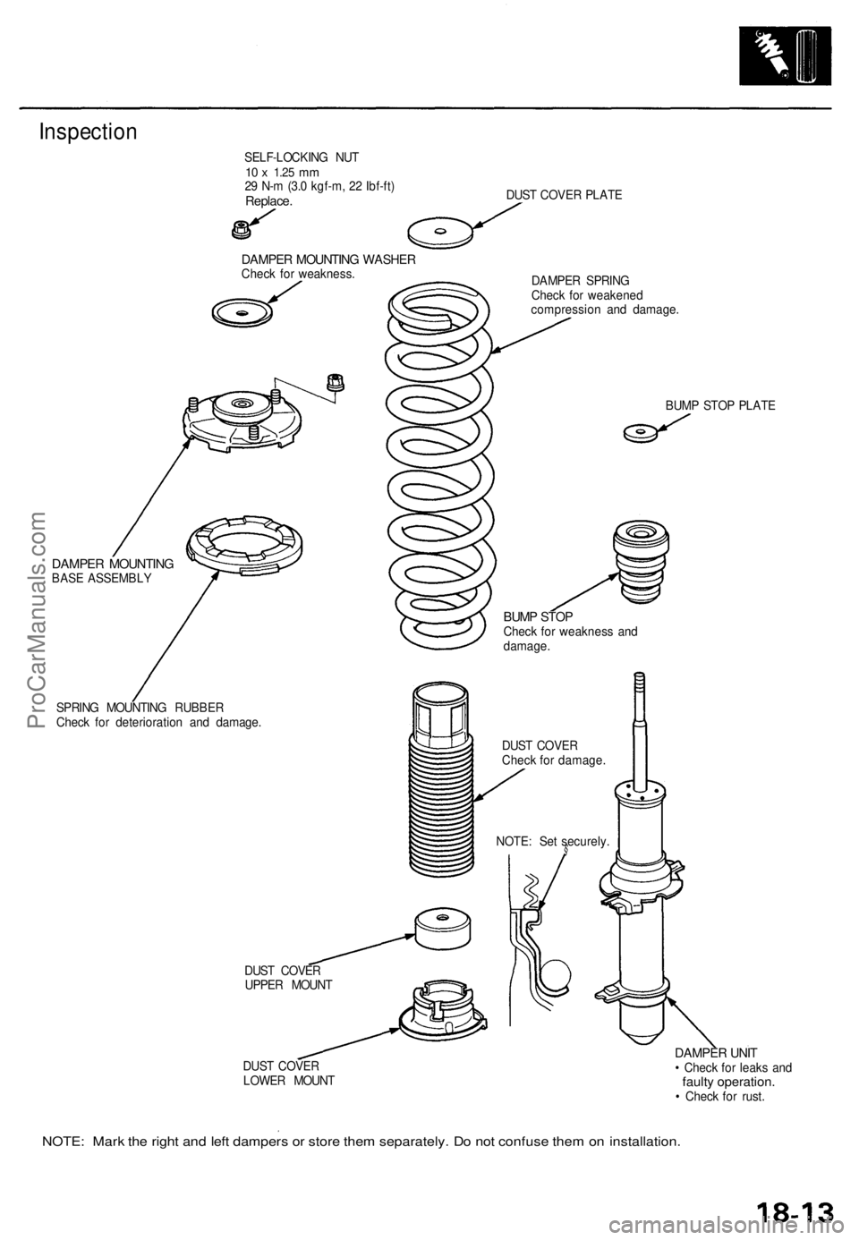
SELF-LOCKIN G NU T10 x 1.2 5 mm29 N- m (3. 0 kgf-m , 2 2 Ibf-ft )Replace .
DAMPER MOUNTIN G WASHE RCheck fo r weakness .
DAMPER MOUNTIN GBASE ASSEMBL Y
SPRIN G MOUNTIN G RUBBE R
Chec k fo r deterioratio n an d damage .
DUS T COVE R
UPPE R MOUN T
DUS T COVE R
LOWE R MOUN T DUS
T COVE R PLAT E
DAMPE R SPRIN G
Chec k fo r weakene d
compressio n an d damage .
BUM P STO P PLAT E
BUMP STO PChec k fo r weaknes s an d
damage .
DAMPER UNI T• Chec k fo r leak s an dfault y operation .• Chec k fo r rust .
NOTE : Mar k th e righ t an d lef t damper s o r stor e the m separately . D o no t confus e the m o n installation.
NOTE : Se t securely .§
DUST COVE R
Chec k fo r damage .
ProCarManuals.com
Page 503 of 1771
Front Dampe r
Reassembl y
1. Instal l th e dampe r uni t o n a sprin g compressor .
NOTE : Follo w th e manufacturer' s instructions .
2 . Assembl e th e dampe r i n revers e orde r o f disassembl y
excep t th e dampe r mountin g washe r an d self-lockin g
nut.
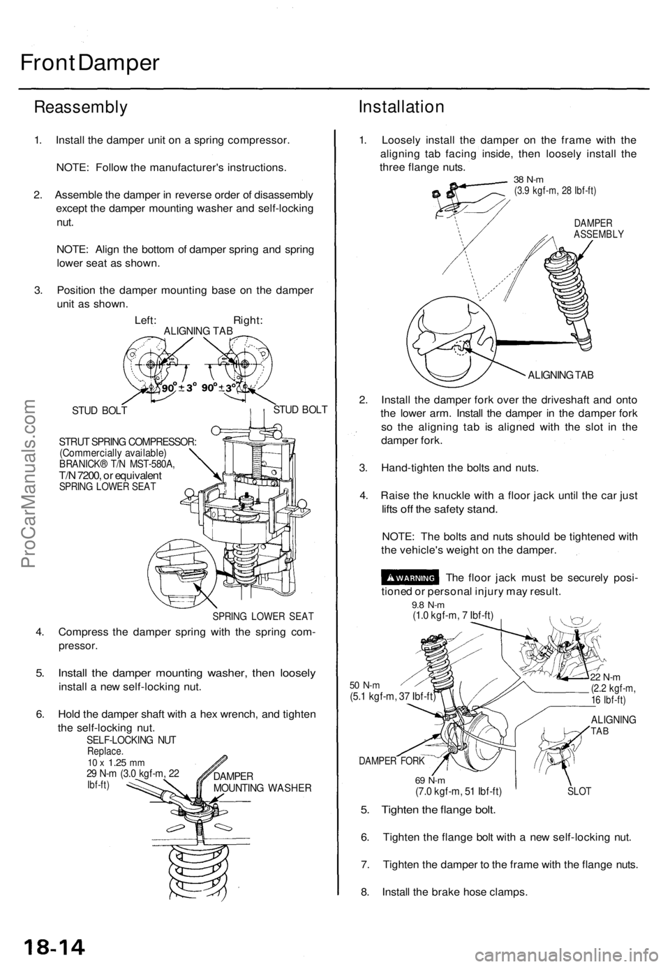
NOTE : Alig n th e botto m o f dampe r sprin g an d sprin g
lowe r sea t a s shown .
3 . Positio n th e dampe r mountin g bas e o n th e dampe r
uni t a s shown .
Left : Right :
ALIGNING TA B
STU D BOL T
STRU T SPRIN G COMPRESSOR :(Commercially available )BRANICK ® T/ N MST-580A ,T/N 7200 , o r equivalen tSPRING LOWE R SEA T
STUD BOL T
ALIGNIN G TAB
2. Instal l th e dampe r for k ove r th e driveshaf t an d ont o
th e lowe r arm . Instal l th e dampe r i n th e dampe r for k
s o th e alignin g ta b i s aligne d wit h th e slo t i n th e
dampe r fork .
3 . Hand-tighte n th e bolt s an d nuts .
4 . Rais e th e knuckl e wit h a floo r jac k unti l th e ca r jus t
lifts of f th e safet y stand .
NOTE : Th e bolt s an d nut s shoul d b e tightene d wit h
th e vehicle' s weigh t o n th e damper .
Th e floo r jac k mus t b e securel y posi -
tione d o r persona l injur y ma y result .
9.8 N- m(1.0 kgf-m , 7 Ibf-ft )
50 N- m(5.1 kgf-m , 3 7 Ibf-ft )
DAMPE R FOR K
69 N- m(7.0 kgf-m , 5 1 Ibf-ft ) SLO T
5. Tighte n th e flang e bolt .
6. Tighte n th e flang e bol t wit h a ne w self-lockin g nut .
7 . Tighte n th e dampe r t o th e fram e wit h th e flang e nuts .
8 . Instal l th e brak e hos e clamps .
Installatio n
1. Loosel y instal l th e dampe r o n th e fram e wit h th e
alignin g ta b facin g inside , the n loosel y instal l th e
thre e flang e nuts .
38 N- m(3.9 kgf-m , 2 8 Ibf-ft )
DAMPE RASSEMBL Y
DAMPERMOUNTIN G WASHE R
SELF-LOCKIN G NU TReplace .10 x 1.2 5 mm29 N- m (3. 0 kgf-m , 2 2Ibf-ft )
4. Compres s th e dampe r sprin g wit h th e sprin g com -
pressor .
5. Instal l th e dampe r mountin g washer , the n loosel y
install a ne w self-lockin g nut .
6 . Hol d th e dampe r shaf t wit h a he x wrench , an d tighte n
th e self-lockin g nut .
SPRIN G LOWE R SEA T
22 N- m(2.2 kgf-m ,16 Ibf-ft )
ALIGNIN GTAB
ProCarManuals.com
Page 515 of 1771
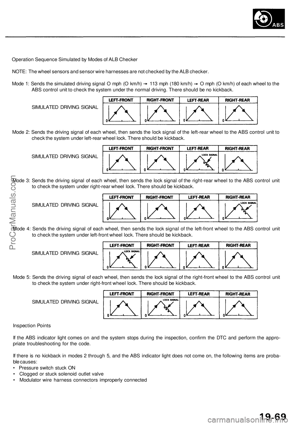
Operation Sequenc e Simulate d b y Mode s o f AL B Checke r
NOTE : Th e whee l sensor s an d senso r wir e harnesse s ar e no t checke d b y th e AL B checker .
Mode 1 : Send s th e simulate d drivin g signa l O mp h ( O km/h ) 11 3 mp h (18 0 km/h ) O mph ( O km/h ) o f eac h whee l t o th e
AB S contro l uni t t o chec k th e syste m unde r th e norma l driving . Ther e shoul d b e n o kickback .
SIMULATE D DRIVIN G SIGNA L
Mod e 2 : Send s th e drivin g signa l o f eac h wheel , the n send s th e loc k signa l o f th e left-rea r whee l t o th e AB S contro l uni t t o
chec k th e syste m unde r left-rea r whee l lock . Ther e shoul d b e kickback .
SIMULATE D DRIVIN G SIGNA L
Mod e 3 : Send s th e drivin g signa l o f eac h wheel , the n send s th e loc k signa l o f th e right-rea r whee l t o th e AB S contro l uni t
t o chec k th e syste m unde r right-rea r whee l lock . Ther e shoul d b e kickback .
SIMULATE D DRIVIN G SIGNA L
Mod e 4 : Send s th e drivin g signa l o f eac h wheel , the n send s th e loc k signa l o f th e left-fron t whee l t o th e AB S contro l uni t
t o chec k th e syste m unde r left-fron t whee l lock . Ther e shoul d b e kickback .
SIMULATE D DRIVIN G SIGNA L
Mod e 5 : Send s th e drivin g signa l o f eac h wheel , the n send s th e loc k signa l o f th e right-fron t whee l t o th e AB S contro l uni t
t o chec k th e syste m unde r right-fron t whee l lock . Ther e shoul d b e kickback .
SIMULATE D DRIVIN G SIGNA L
Inspectio n Point s
I f th e AB S indicato r ligh t come s o n an d th e syste m stop s during the inspection , confir m th e DT C an d perfor m th e appro -
priat e troubleshootin g fo r th e code .
I f ther e is n o kickbac k i n mode s 2 throug h 5 , an d th e AB S indicato r ligh t doe s no t com e on , th e followin g item s ar e proba -
bl e causes :
• Pressur e switc h stuc k O N
• Clogge d o r stuc k solenoi d outle t valv e
• Modulato r wir e harnes s connector s improperl y connecte d
ProCarManuals.com
Page 516 of 1771
Master Cylinde r
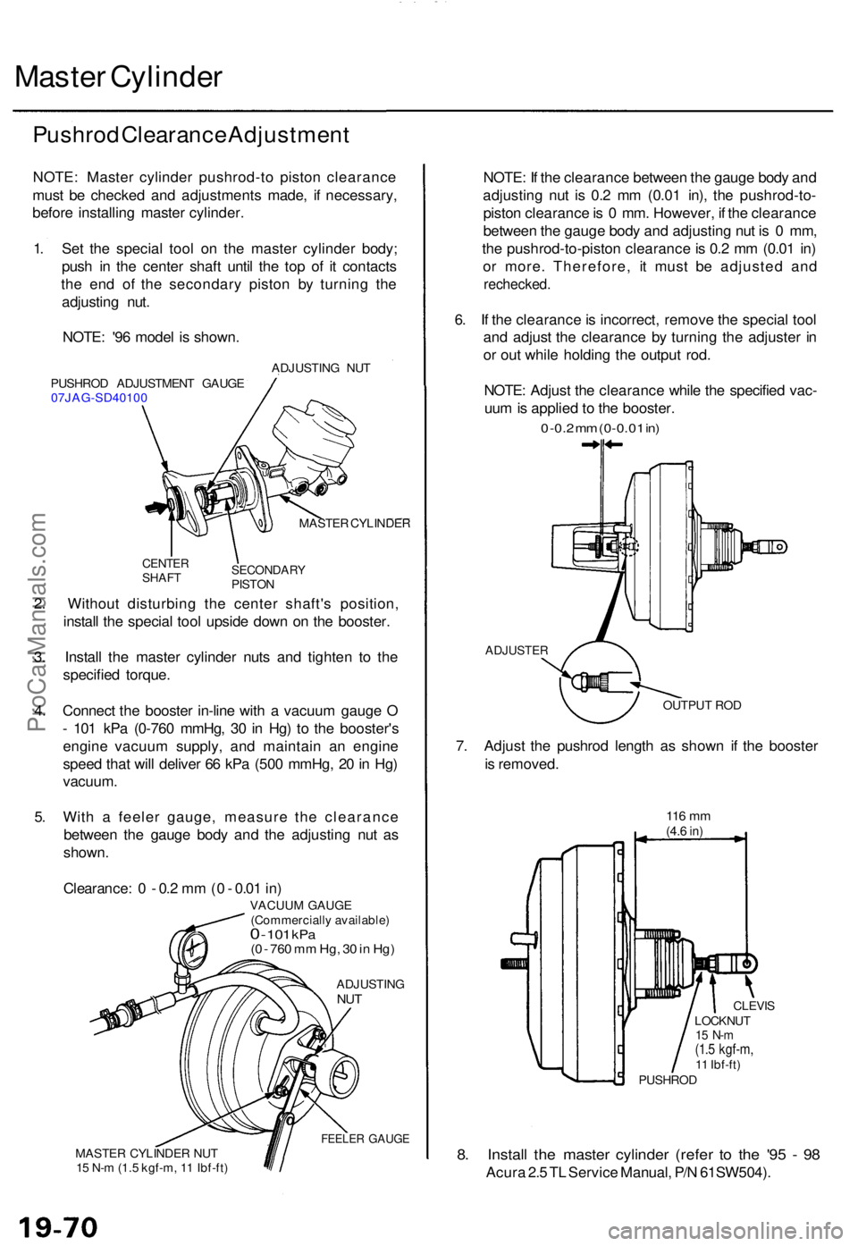
Pushrod Clearanc e Adjustmen t
NOTE: Maste r cylinde r pushrod-t o pisto n clearanc e
mus t b e checke d an d adjustment s made , i f necessary ,
befor e installin g maste r cylinder .
1 . Se t th e specia l too l o n th e maste r cylinde r body ;
pus h i n th e cente r shaf t unti l th e to p o f i t contact s
th e en d o f th e secondar y pisto n b y turnin g th e
adjustin g nut .
NOTE : '9 6 mode l i s shown .
PUSHRO D ADJUSTMEN T GAUG E
07JAG-SD4010 0 ADJUSTIN
G NU T
MASTE R CYLINDE R
CENTERSHAFTSECONDAR YPISTON
2. Withou t disturbin g th e cente r shaft' s position ,
instal l th e specia l too l upsid e dow n o n th e booster .
3 . Instal l th e maste r cylinde r nut s an d tighte n t o th e
specifie d torque .
4 . Connec t th e booste r in-lin e wit h a vacuu m gaug e O
- 10 1 kP a (0-76 0 mmHg , 3 0 in Hg ) t o th e booster' s
engin e vacuu m supply , an d maintai n a n engin e
spee d tha t wil l delive r 6 6 kP a (50 0 mmHg , 2 0 in Hg )
vacuum .
5 . Wit h a feele r gauge , measur e th e clearanc e
betwee n th e gaug e bod y an d th e adjustin g nu t a s
shown .
Clearance : 0 - 0.2 m m (0 - 0.0 1 in )
VACUU M GAUG E
(Commerciall y available )
0 - 101 kP a(0 - 76 0 m m Hg , 3 0 in Hg )
ADJUSTIN GNUT
FEELE R GAUG EMASTE R CYLINDE R NU T
1 5 N- m (1. 5 kgf-m , 1 1 Ibf-ft )
NOTE : I f th e clearanc e betwee n th e gaug e bod y an d
adjustin g nu t i s 0. 2 m m (0.0 1 in) , th e pushrod-to -
pisto n clearanc e is 0 mm . However , i f th e clearanc e
betwee n th e gaug e bod y an d adjustin g nu t i s 0 mm ,
th e pushrod-to-pisto n clearanc e is 0. 2 m m (0.0 1 in )
o r more . Therefore , i t mus t b e adjuste d an d
rechecked .
6. I f th e clearanc e is incorrect , remov e th e specia l too l
an d adjus t th e clearanc e b y turnin g th e adjuste r i n
o r ou t whil e holdin g th e outpu t rod .
NOTE : Adjus t th e clearanc e whil e th e specifie d vac -
uu m is applie d t o th e booster .
0 -0. 2 m m (0-0.0 1 in )
ADJUSTE R
OUTPUT RO D
7. Adjus t th e pushro d lengt h a s show n i f th e booste r
i s removed .
116 m m(4.6 in)
8. Instal l th e maste r cylinde r (refe r t o th e '9 5 - 9 8
Acur a 2. 5 T L Servic e Manual , P/ N 61SW504) .
LOCKNUT15 N- m(1.5 kgf-m ,11 Ibf-ft )
CLEVI S
PUSHRO D
ProCarManuals.com
Page 530 of 1771
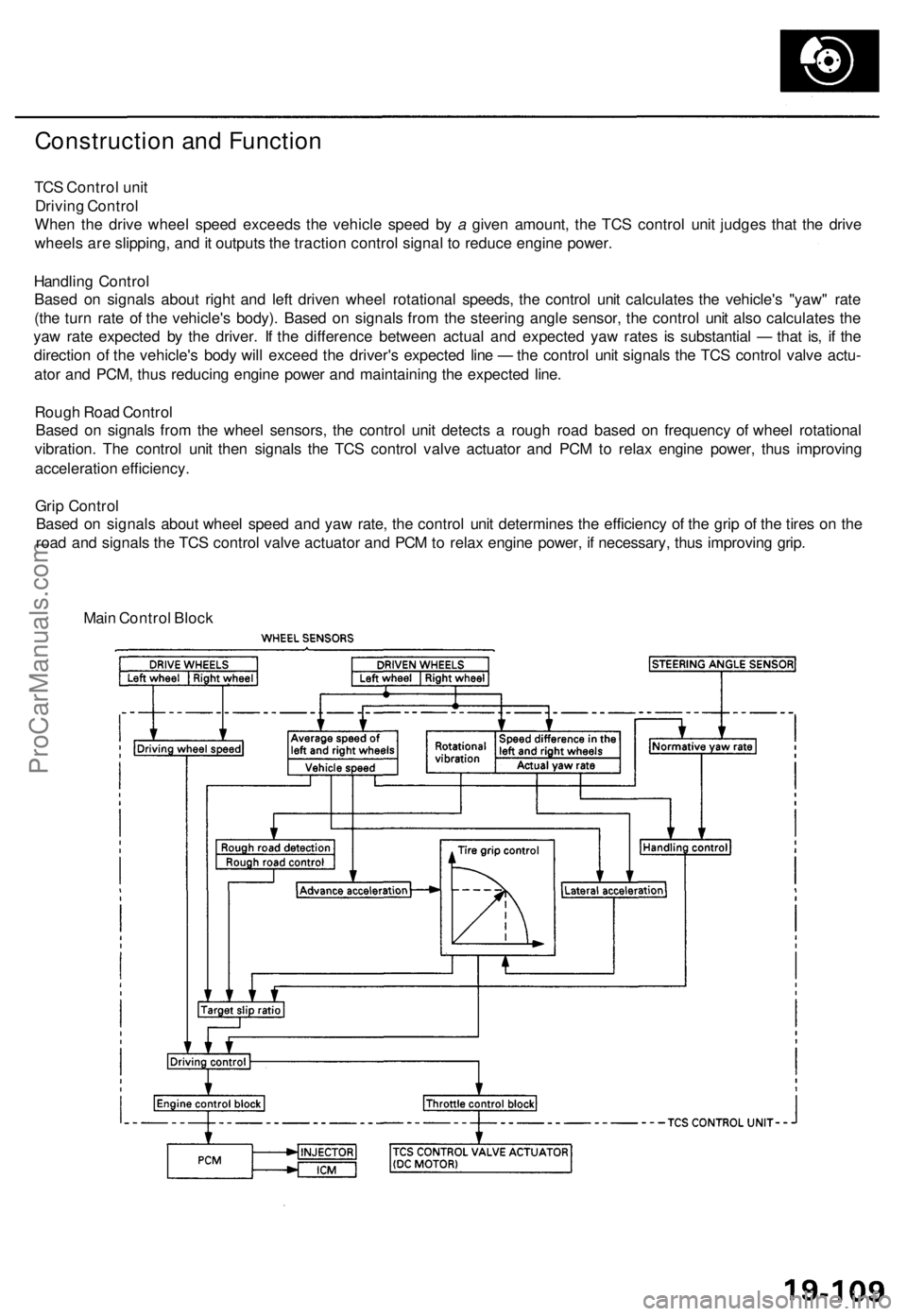
Construction and Function
TCS Control unit
Driving Control
When the drive wheel speed exceeds the vehicle speed by a given amount, the TCS control unit judges that the drive
wheels are slipping, and it outputs the traction control signal to reduce engine power.
Handling Control
Based on signals about right and left driven wheel rotational speeds, the control unit calculates the vehicle's "yaw" rate
(the turn rate of the vehicle's body). Based on signals from the steering angle sensor, the control unit also calculates the
yaw rate expected by the driver. If the difference between actual and expected yaw rates is substantial — that is, if the
direction of the vehicle's body will exceed the driver's expected line — the control unit signals the TCS control valve actu-
ator and PCM, thus reducing engine power and maintaining the expected line.
Rough Road Control
Based on signals from the wheel sensors, the control unit detects a rough road based on frequency of wheel rotational
vibration. The control unit then signals the TCS control valve actuator and PCM to relax engine power, thus improving
acceleration efficiency.
Grip Control
Based on signals about wheel speed and yaw rate, the control unit determines the efficiency of the grip of the tires on the
road and signals the TCS control valve actuator and PCM to relax engine power, if necessary, thus improving grip.
Main Control BlockProCarManuals.com
Page 539 of 1771
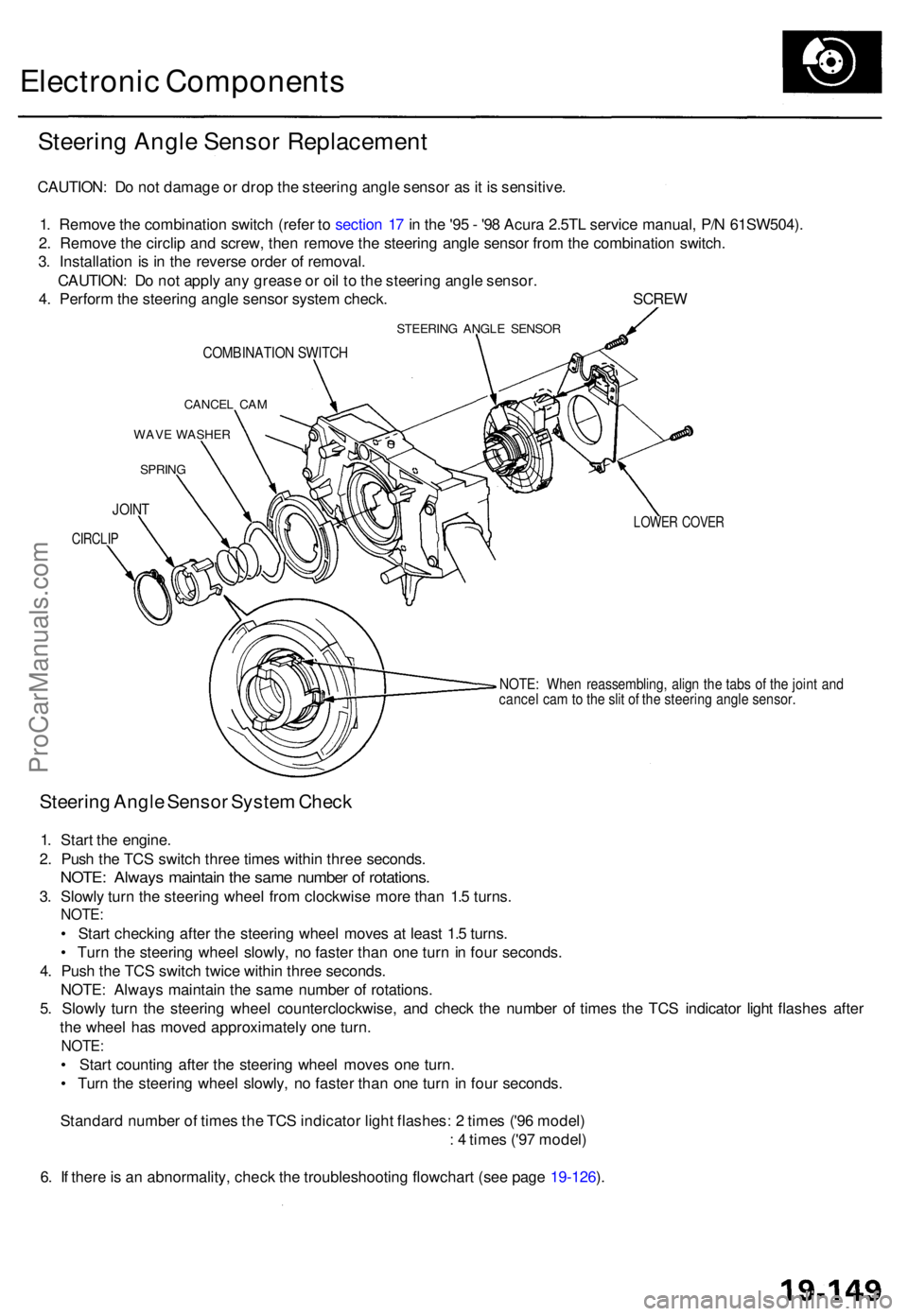
Electronic Component s
Steering Angl e Senso r Replacemen t
CAUTION: D o no t damag e o r dro p th e steerin g angl e senso r a s it i s sensitive .
1 . Remov e th e combinatio n switc h (refe r t o sectio n 1 7 in th e '9 5 - '9 8 Acur a 2.5T L servic e manual , P/ N 61SW504) .
2 . Remov e th e circli p an d screw , the n remov e th e steerin g angl e senso r fro m th e combinatio n switch .
3 . Installatio n i s i n th e revers e orde r o f removal .
CAUTION : D o no t appl y an y greas e o r oi l t o th e steerin g angl e sensor .
4 . Perfor m th e steerin g angl e senso r syste m check . SCRE W
STEERING ANGL E SENSO R
COMBINATIO N SWITC H
CANCE L CA M
WAV E WASHE R
SPRING
LOWER COVE R
NOTE: Whe n reassembling , alig n th e tab s o f th e join t an d
cance l ca m to th e sli t o f th e steerin g angl e sensor .
Steering Angl e Senso r Syste m Chec k
1. Star t th e engine .
2 . Pus h th e TC S switc h thre e time s withi n thre e seconds .
NOTE: Alway s maintai n th e sam e numbe r o f rotations .
3. Slowl y tur n th e steerin g whee l fro m clockwis e mor e tha n 1. 5 turns .
NOTE :
• Star t checkin g afte r th e steerin g whee l move s a t leas t 1. 5 turns .
• Tur n th e steerin g whee l slowly , n o faste r tha n on e tur n in fou r seconds .
4 . Pus h th e TC S switc h twic e withi n thre e seconds .
NOTE : Alway s maintai n th e sam e numbe r o f rotations .
5 . Slowl y tur n th e steerin g whee l counterclockwise , an d chec k th e numbe r o f time s th e TC S indicato r ligh t flashe s afte r
th e whee l ha s move d approximatel y on e turn .
NOTE :
• Star t countin g afte r th e steerin g whee l move s on e turn .
• Tur n th e steerin g whee l slowly , n o faste r tha n on e tur n i n fou r seconds .
Standar d numbe r o f time s th e TC S indicato r ligh t flashes : 2 time s ('9 6 model )
: 4 time s ('9 7 model )
6 . I f ther e is a n abnormality , chec k th e troubleshooting flowchart (se e pag e 19-126 ).
JOIN T
CIRCLI P
ProCarManuals.com
Page 545 of 1771
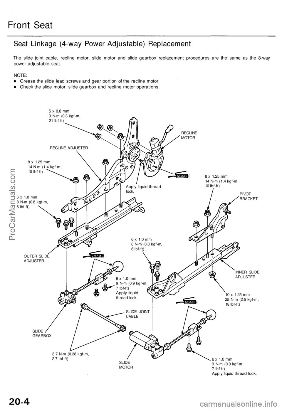
Front Seat
Seat Linkage (4-way Power Adjustable) Replacement
The slide joint cable, recline motor, slide motor and slide gearbox replacement procedures are the same as the 8-way
power adjustable seat.
NOTE:
Grease the slide lead screws and gear portion of the recline motor.
Check the slide motor, slide gearbox and recline motor operations.
5 x 0.8 mm
3 N-m (0.3 kgf-m,
21 Ibf-ft)
8 x
1.25
mm
14 N-m (1.4 kgf-m,
10 Ibf-ft)
6 x 1.0 mm
8 N-m (0.8 kgf-m,
6 Ibf-ft)
RECLINE
MOTOR
8 x
1.25
mm
14 N-m (1.4 kgf-m,
10 Ibf-ft)
OUTER SLIDE
ADJUSTER
SLIDE
GEARBOX
6 x 1.0 mm
8 N-m (0.8 kgf-m
6 Ibf-ft)
3.7 N-m (0.38 kgf-m,
2.7 Ibf-ft)
PIVOT
BRACKET
6 x 1.0 mm
9 N-m (0.9 kgf-m,
7 Ibf-ft)
Apply liquid
thread lock.
INNER SLIDE
ADJUSTER
10 x
1.25
mm
25 N-m (2.5 kgf-m,
18 Ibf-ft)
SLIDE
MOTOR
6 x 1.0 mm
9 N-m (0.9 kgf-m,
7 Ibf-ft)
Apply liquid thread lock.
SLIDE JOINT
CABLE
Apply liquid thread
lock.
RECLINE ADJUSTERProCarManuals.com