Page 724 of 1771
Engine Removal/Installatio n
Removal (cont'd )
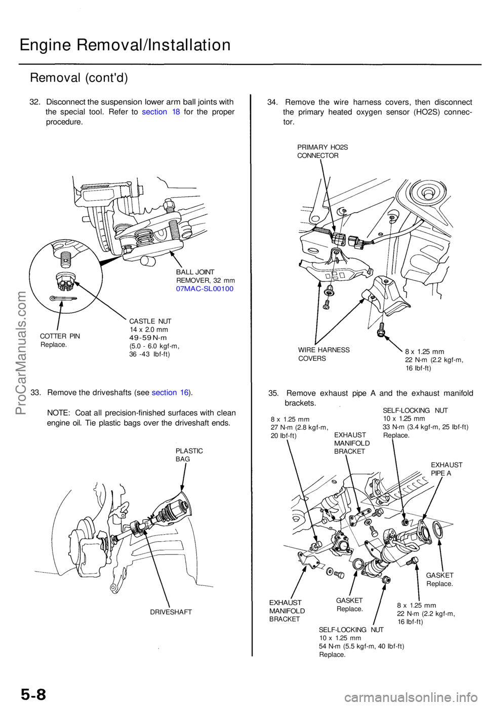
32. Disconnec t th e suspensio n lowe r ar m bal l joint s wit h
the specia l tool . Refe r t o sectio n 1 8 fo r th e prope r
procedure .
BALL JOIN TREMOVER , 3 2 m m07MAC-SL0010 0
COTTER PI N
Replace . CASTL
E NU T14 x 2. 0 m m49-5 9 N-m(5.0 - 6. 0 kgf-m ,
3 6 -4 3 Ibf-ft )
33. Remov e th e driveshaft s (se e sectio n 16 ).
NOTE : Coa t al l precision-finishe d surface s wit h clea n
engin e oil . Ti e plasti c bag s ove r th e driveshaf t ends .
PLASTI CBAG
DRIVESHAF T
34. Remov e th e wir e harnes s covers , the n disconnec t
th e primar y heate d oxyge n senso r (HO2S ) connec -
tor.
PRIMAR Y HO2 S
CONNECTO R
WIR E HARNES S
COVERS8 x 1.2 5 m m22 N- m (2. 2 kgf-m ,
1 6 Ibf-ft )
EXHAUS TMANIFOL DBRACKET
GASKETReplace .
8 x 1.2 5 mm22 N- m (2. 2 kgf-m ,
1 6 Ibf-ft )
SELF-LOCKIN G NU T
10 x 1.2 5 mm54 N- m (5. 5 kgf-m , 4 0 Ibf-ft )
Replace .
GASKE
T
Replace .
35. Remov e exhaus t pip e A an d th e exhaus t manifol d
brackets .
SELF-LOCKIN G NU T10 x 1.2 5 mm33 N- m (3. 4 kgf-m , 2 5 Ibf-ft )
Replace .
EXHAUS T
PIP E A
EXHAUS
T
MANIFOL DBRACKET
8 x 1.2 5 mm27 N- m (2. 8 kgf-m ,
2 0 Ibf-ft )
ProCarManuals.com
Page 727 of 1771
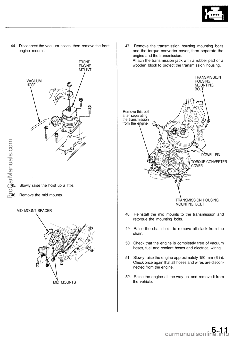
44. Disconnect the vacuum hoses, then remove the front
engine mounts.
VACUUM
HOSE
FRONT
ENGINE
MOUNT
45. Slowly raise the hoist up a little.
46. Remove the mid mounts.
MID MOUNT SPACER
MID MOUNTS
47. Remove the transmission housing mounting bolts
and the torque converter cover, then separate the
engine and the transmission.
Attach the transmission jack with a rubber pad or a
wooden block to protect the transmission housing.
Remove this bolt
after separating
the transmission
from the engine.
TRANSMISSION
HOUSING
MOUNTING
BOLT
DOWEL PIN
TORQUE CONVERTER
COVER
TRANSMISSION HOUSING
MOUNTING BOLT
48. Reinstall the mid mounts to the transmission and
retorque the mounting bolts.
49. Raise the chain hoist to remove all slack from the
chain.
50. Check that the engine is completely free of vacuum
hoses, fuel and coolant hoses and electrical wiring.
51. Slowly raise the engine approximately 150 mm (6 in).
Check once again that all hoses and wires are discon-
nected from the engine.
52. Raise the engine all the way up, and remove it from
the vehicle.ProCarManuals.com
Page 728 of 1771
Engine Removal/Installatio n
Installation
Bracket Bolt s Torqu e Specifications :
ENGINE HANGE R
P/ S PUM P
BRACKE T
10 x 1.2 5 mm49 N- m (5. 0 kgf-m ,36 Ibf-ft )
ALTERNATO RBRACKET
10 x 1.2 5 mm49 N- m (5. 0 kgf-m ,
3 6 Ibf-ft )
RIGH T FRON T MOUN T
BRACKE T
10 x 1.2 5 mm44 N- m (4. 5 kgf-m ,33 Ibf-ft )
LEFT FRON T MOUN TBRACKE T
A/CCOMPRESSO RBRACKET
12 x 1.2 5 mm54 N- m (5. 5 kgf-m ,
4 0 Ibf-ft )
10 x 1.2 5 mm49 N- m (5. 0 kgf-m ,
3 6 Ibf-ft )
10 x 1.2 5 mm54 N- m (5. 5 kgf-m , 4 0 Ibf-ft )
8 x 1.2 5 mm22 N- m (2. 2 kgf-m ,
1 6 Ibf-ft )
10 x 1.2 5 mm54 N- m (5. 5 kgf-m , 4 0 Ibf-ft )
NOTE : Whe n installin g th e A/ C compresso r
bracket , tighte n th e bolt s o n th e oi l pa n
first , the n thos e o n th e cylinde r block .
8 x 1.2 5 mm34 N- m (3. 5 kgf-m , 2 5 Ibf-ft )
ProCarManuals.com
Page 737 of 1771
Valve Clearanc e
Adjustmen t
NOTE:
• Valve s shoul d b e adjuste d onl y whe n th e cylinde r
head temperatur e is les s tha n 100° F (38°C) .
• Afte r adjusting , retorqu e th e crankshaf t pulle y bol t t o
24 5 N- m (25. 0 kgf-m , 18 1 Ibf-ft) .
1 . Remov e th e cylinde r hea d cover .
NOTE : Refe r t o page s 6-35 , 6-3 6 whe n installin g th e
cylinde r hea d cover .
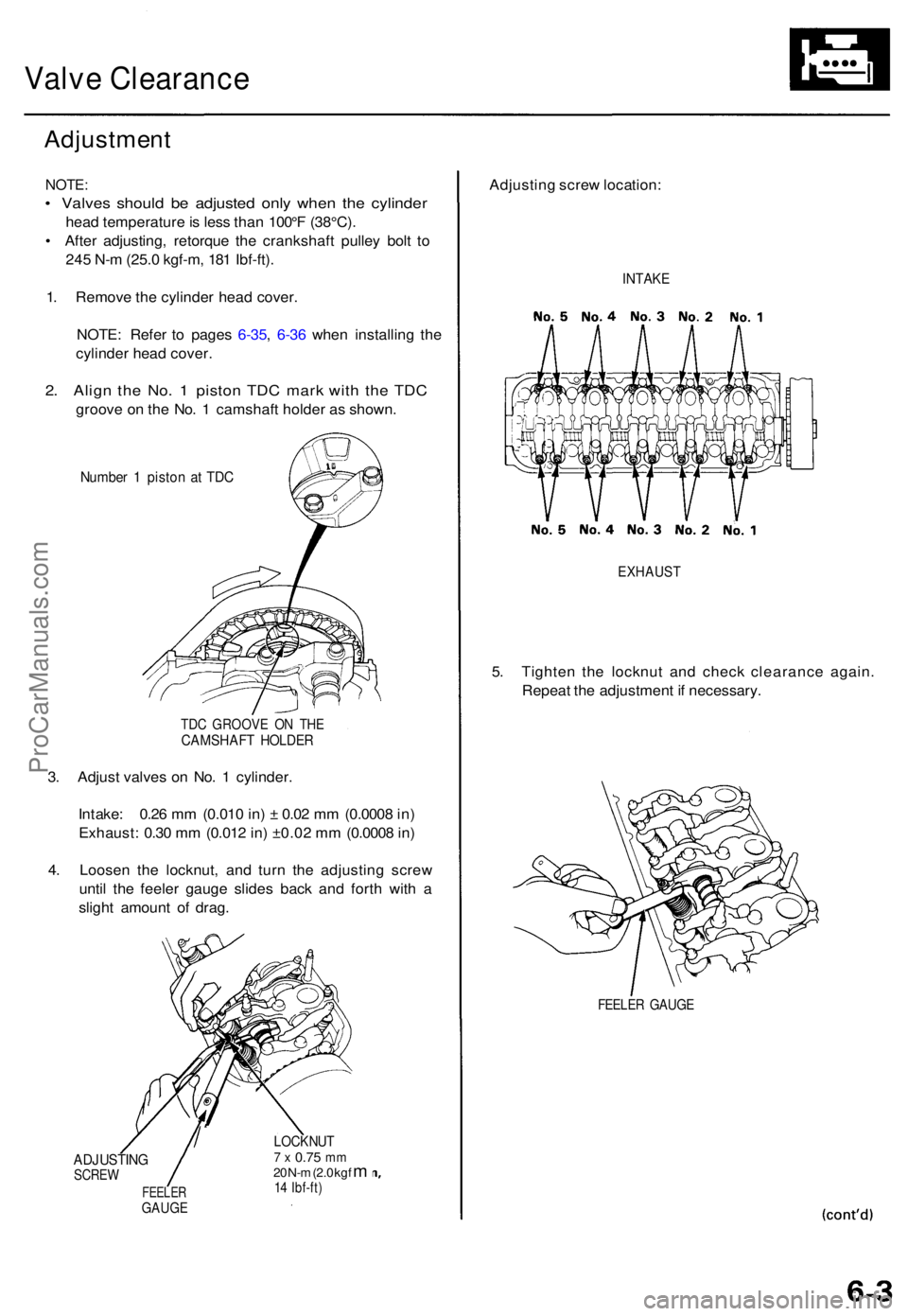
2. Alig n th e No . 1 pisto n TD C mar k wit h th e TD C
groov e o n th e No . 1 camshaf t holde r a s shown .
Numbe r 1 pisto n a t TD C
TDC GROOV E O N TH ECAMSHAF T HOLDE R
3. Adjus t valve s o n No . 1 cylinder .
Intake : 0.2 6 m m (0.01 0 in ) ± 0.0 2 m m (0.000 8 in )
Exhaust : 0.3 0 m m (0.01 2 in ) ±0.0 2 m m (0.000 8 in )
4 . Loose n th e locknut , an d tur n th e adjustin g scre w
unti l th e feele r gaug e slide s bac k an d fort h wit h a
sligh t amoun t o f drag .
ADJUSTIN GSCREW
FEELE RGAUGE
LOCKNU T7 x 0.7 5 mm20 N- m (2. 0 kg f m14 Ibf-ft )
Adjustin g scre w location :
EXHAUS T
5. Tighte n th e locknu t an d chec k clearanc e again .
Repea t th e adjustmen t i f necessary .
FEELER GAUG E
INTAKE
ProCarManuals.com
Page 738 of 1771
Valve Clearanc e
Adjustmen t (cont'd )
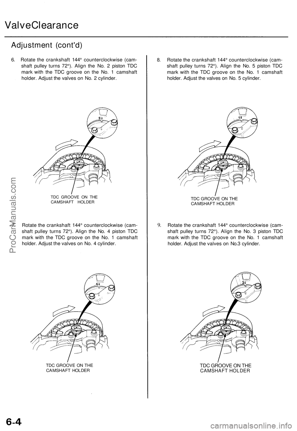
6. Rotat e th e crankshaf t 144 ° counterclockwis e (cam -
shaf t pulle y turn s 72°) . Alig n th e No . 2 pisto n TD C
mar k wit h th e TD C groov e o n th e No . 1 camshaf t
holder . Adjus t th e valve s o n No . 2 cylinder .
7.
TD C GROOV E O N TH ECAMSHAF T HOLDE R
Rotate th e crankshaf t 144 ° counterclockwis e (cam -
shaf t pulle y turn s 72°) . Alig n th e No . 4 pisto n TD C
mar k wit h th e TD C groov e o n th e No . 1 camshaf t
holder . Adjus t th e valve s o n No . 4 cylinder .
TDC GROOV E O N TH ECAMSHAF T HOLDE R
8.Rotat e th e crankshaf t 144 ° counterclockwis e (cam -
shaf t pulle y turn s 72°) . Alig n th e No . 5 pisto n TD C
mar k wit h th e TD C groov e o n th e No . 1 camshaf t
holder . Adjus t th e valve s o n No . 5 cylinder .
9.
TD C GROOV E O N TH ECAMSHAF T HOLDE R
Rotate th e crankshaf t 144 ° counterclockwis e (cam -
shaf t pulle y turn s 72°) . Alig n th e No . 3 pisto n TD C
mar k wit h th e TD C groov e o n th e No . 1 camshaf t
holder . Adjust the valve s o n No. 3 cylinder .
TDC GROOVE ON THE
CAMSHAFT HOLDER
ProCarManuals.com
Page 743 of 1771
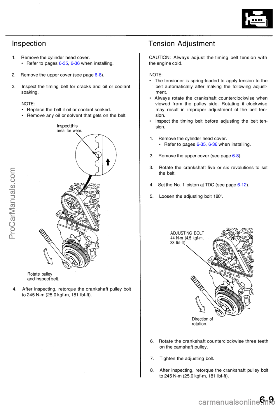
Inspection
1. Remov e th e cylinde r hea d cover .
• Refe r t o page s 6-35 , 6-3 6 whe n installing .
2 . Remov e th e uppe r cove r (se e pag e 6-8 ).
3 . Inspec t th e timin g bel t fo r crack s an d oi l o r coolan t
soaking .
NOTE:
• Replac e th e bel t i f oi l o r coolan t soaked .
• Remov e an y oi l o r solven t tha t get s o n th e belt .
Inspec t thi s
are a fo r wear .
Tensio n Adjustmen t
Rotate pulle yand inspec t belt .
4 . Afte r inspecting , retorqu e th e crankshaf t pulle y bol t
t o 24 5 N- m (25. 0 kgf-m , 18 1 Ibf-ft) . CAUTION
: Alway s adjus t th e timin g bel t tensio n wit h
th e engin e cold .
NOTE :
• Th e tensione r i s spring-loade d t o appl y tensio n t o th e
bel t automaticall y afte r makin g th e followin g adjust -
ment .
• Alway s rotat e th e crankshaf t counterclockwis e whe n
viewe d fro m th e pulle y side . Rotatin g i t clockwis e
ma y resul t i n imprope r adjustmen t of the bel t ten -
sion .
• Inspec t th e timin g bel t befor e adjustin g th e bel t ten -
sion .
1 . Remov e th e cylinde r hea d cover .
• Refe r t o page s 6-35 , 6-3 6 whe n installing .
2 . Remov e th e uppe r cove r (se e pag e 6-8 ).
3 . Rotat e th e crankshaf t fiv e o r si x revolution s t o se t
th e belt .
4 . Se t th e No . 1 pisto n a t TD C (se e pag e 6-12 ).
5 . Loose n th e adjustin g bol t 180° .
ADJUSTIN G BOL T44 N- m (4. 5 kgf-m ,
3 3 Ibf-ft )
Directio n o frotation .
6. Rotat e th e crankshaf t counterclockwis e thre e teet h
o n th e camshaf t pulley .
7 . Tighte n th e adjustin g bolt .
8 . Afte r inspecting , retorqu e th e crankshaf t pulle y bol t
t o 24 5 N- m (25. 0 kgf-m , 18 1 Ibf-ft) .
ProCarManuals.com
Page 744 of 1771
Tinning Bel t
Remova l
NOTE:
2.
3.
Replac e th e timin g bel t a t 105,00 0 mile s (168,00 0 km )
accordin g t o th e maintenanc e schedul e (norma l con -
ditions/sever e conditions) .
I f th e vehicl e regularl y i s drive n i n on e o r mor e o f th e
followin g conditions , replac e th e timin g bel t a t 60,00 0
mile s (U.S.A. ) 100,00 0 k m (Canada) .
• I n ver y hig h temperature s (ove r 110°F , 43°C) .
• I n ver y lo w temperature s (unde r -20°F , -29°C) .
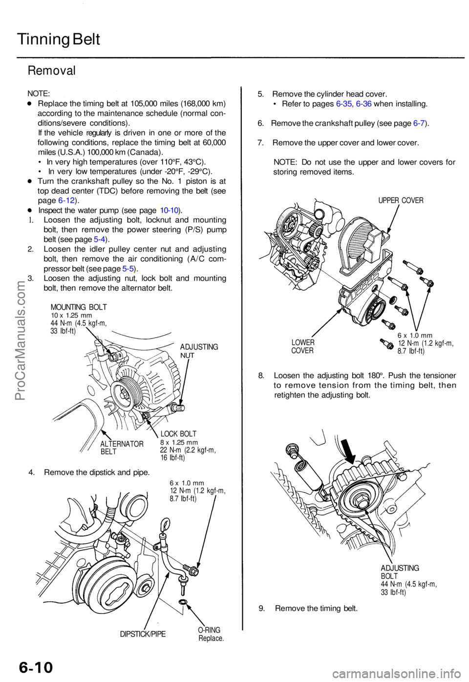
Tur n th e crankshaf t pulle y s o th e No . 1 pisto n i s a t
to p dea d cente r (TDC ) befor e removin g th e bel t (se e
page 6-12).
Inspec t th e wate r pum p (se e pag e 10-10 ).
Loose n th e adjustin g bolt , locknu t an d mountin g
bolt , the n remov e th e powe r steerin g (P/S ) pum p
bel t (se e pag e 5-4 ).
Loose n th e idle r pulle y cente r nu t an d adjustin g
bolt , the n remov e th e ai r conditionin g (A/ C com -
presso r bel t (se e pag e 5-5 ).
Loose n th e adjustin g nut , loc k bol t an d mountin g
bolt , the n remov e th e alternato r belt .
MOUNTIN G BOL T10 x 1.2 5 mm44 N- m (4. 5 kgf-m ,
3 3 Ibf-ft )
ADJUSTIN GNUT
ALTERNATO RBELT
4. Remov e th e dipstic k an d pipe .
LOCK BOL T8 x 1.2 5 mm22 N- m (2. 2 kgf-m ,
1 6 Ibf-ft )
6 x 1. 0 m m12 N- m (1. 2 kgf-m ,
8. 7 Ibf-ft )
DIPSTICK/PIP EO-RINGReplace .
5. Remov e th e cylinde r hea d cover .
• Refe r t o page s 6-35 , 6-3 6 whe n installing .
6 . Remov e th e crankshaf t pulle y (se e pag e 6-7 ).
7 . Remov e th e uppe r cove r an d lowe r cover .
NOTE : D o no t us e th e uppe r an d lowe r cover s fo r
storin g remove d items .
UPPER COVE R
LOWE R
COVE R
6 x 1. 0 m m12 N- m (1. 2 kgf-m ,
8. 7 Ibf-ft )
8. Loose n th e adjustin g bol t 180° . Pus h th e tensione r
to remov e tensio n fro m th e timin g belt , the n
retighte n th e adjustin g bolt .
ADJUSTIN GBOLT
4 4 N- m (4. 5 kgf-m ,
3 3 Ibf-ft )
9. Remov e th e timin g belt .
1.
ProCarManuals.com
Page 746 of 1771
Timing Bel t
Installatio n (cont'd )
6. Instal l th e crankshaf t pulley , the n tighte n th e pulle y
bol t (se e pag e 6-7 ).
7 . Rotat e th e crankshaf t pulle y abou t fiv e o r si x turn s
counterclockwis e s o tha t th e timin g bel t position s o n
th e pulleys .
8 . Adjus t th e timin g bel t tensio n (se e pag e 6-9 ).
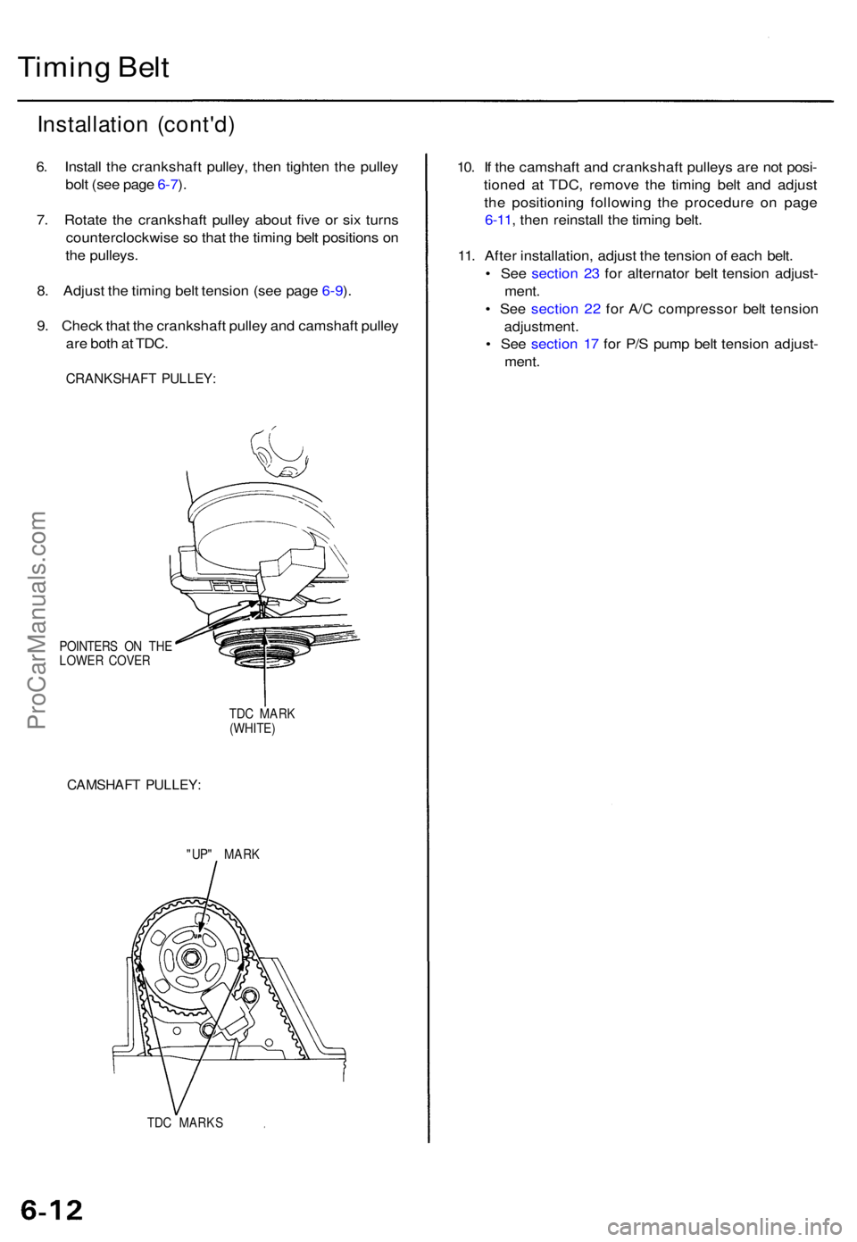
9 . Chec k tha t th e crankshaf t pulle y an d camshaf t pulle y
ar e bot h a t TDC .
CRANKSHAF T PULLEY :
POINTER S O N TH E
LOWE R COVE R
TDC MAR K
(WHITE )
CAMSHAF T PULLEY :
"UP" MAR K
TD C MARK S
10. I f th e camshaf t an d crankshaf t pulley s ar e no t posi -
tione d a t TDC , remov e th e timin g bel t an d adjus t
th e positionin g followin g th e procedur e o n pag e
6-11 , the n reinstal l th e timin g belt .
11 . Afte r installation , adjus t th e tensio n o f eac h belt .
• Se e sectio n 2 3 fo r alternato r bel t tensio n adjust -
ment .
• Se e sectio n 2 2 fo r A/ C compresso r bel t tensio n
adjustment .
• Se e sectio n 1 7 fo r P/ S pum p bel t tensio n adjust -
ment .
ProCarManuals.com