Page 780 of 1771
Drive Plat e Connectin
g Ro d an dCrankshaf t
Replacemen tEnd Pla y
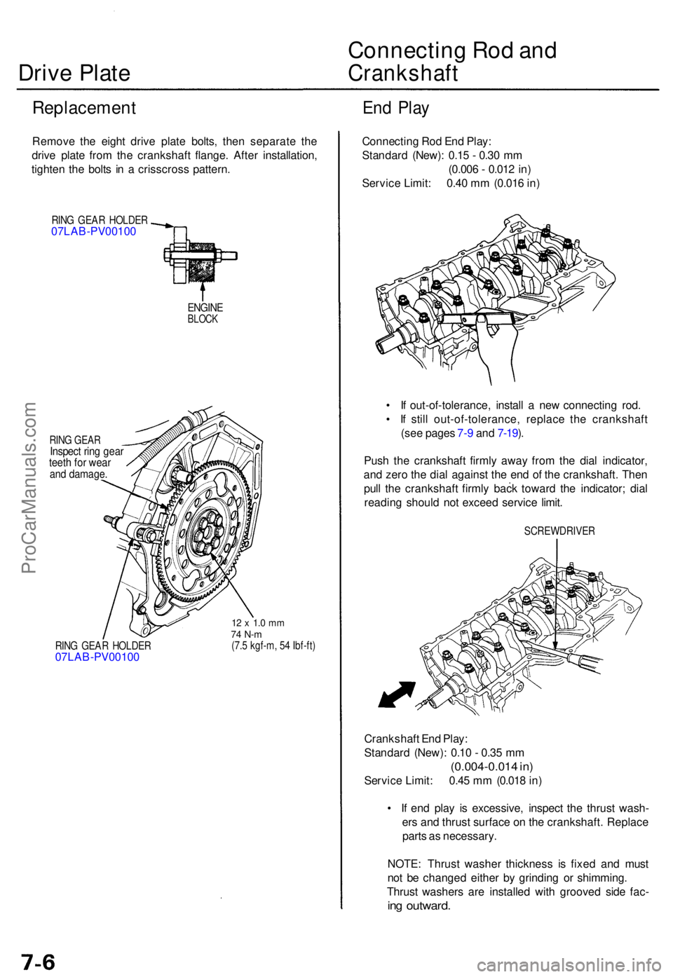
Remov e th e eigh t driv e plat e bolts , the n separat e th e
driv e plat e fro m th e crankshaf t flange . Afte r installation ,
tighte n th e bolt s i n a crisscros s pattern .
RING GEA R HOLDE R07LAB-PV00100
ENGINEBLOCK
RING GEA RInspec t rin g gea rteeth fo r wea rand damage .
RING GEA R HOLDE R07LAB-PV0010 0
12 x 1. 0 m m74 N- m(7.5 kgf-m , 5 4 Ibf-ft )
Connectin g Ro d En d Play :
Standar d (New) : 0.1 5 - 0.3 0 m m
(0.00 6 - 0.01 2 in )
Servic e Limit : 0.4 0 m m (0.01 6 in )
• I f out-of-tolerance , instal l a ne w connectin g rod .
• I f stil l out-of-tolerance , replac e th e crankshaf t
(se e page s 7- 9 an d 7-19 ).
Pus h th e crankshaf t firml y awa y fro m th e dia l indicator ,
an d zer o th e dia l agains t th e en d o f th e crankshaft . The n
pul l th e crankshaf t firml y bac k towar d th e indicator ; dia l
readin g shoul d no t excee d servic e limit .
SCREWDRIVE R
Crankshaft En d Play :
Standar d (New) : 0.1 0 - 0.3 5 m m
(0.004-0.01 4 in )
Servic e Limit : 0.4 5 m m (0.01 8 in )
• I f en d pla y i s excessive , inspec t th e thrus t wash -
er s an d thrus t surfac e o n th e crankshaft . Replac e
part s a s necessary .
NOTE : Thrus t washe r thicknes s i s fixe d an d mus t
no t b e change d eithe r b y grindin g o r shimming .
Thrus t washer s ar e installe d wit h groove d sid e fac -
ing outward .
ProCarManuals.com
Page 788 of 1771
Crankshaft
Inspection
• Clean the crankshaf t oi l passage s wit h pip e cleaner s
or a suitabl e brush .
• Chec k th e keywa y an d threads .
Alignmen t
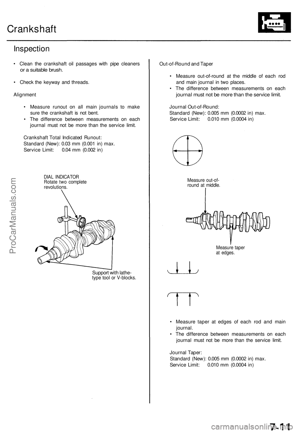
• Measur e runou t o n al l mai n journal s t o mak e
sur e th e crankshaf t i s no t bent .
• Th e differenc e betwee n measurement s o n eac h
journa l mus t no t b e mor e tha n th e servic e limit .
Crankshaf t Tota l Indicate d Runout :
Standar d (New) : 0.0 3 m m (0.00 1 in ) max .
Servic e Limit : 0.0 4 m m (0.00 2 in )
DIA L INDICATO RRotate tw o complet erevolutions .
Support wit h lathe -type too l o r V-blocks .
Out-of-Roun d an d Tape r
• Measur e out-of-roun d a t th e middl e o f eac h ro d
an d mai n journa l i n tw o places .
• Th e differenc e betwee n measurement s o n eac h
journa l mus t no t b e mor e tha n th e servic e limit .
Journa l Out-of-Round :
Standar d (New) : 0.00 5 m m (0.000 2 in ) max .
Servic e Limit : 0.01 0 m m (0.000 4 in )
Measur e out-of -round a t middle .
Measur e tape rat edges .
• Measur e tape r a t edge s o f eac h ro d an d mai n
journal .
• Th e differenc e betwee n measurement s o n eac h
journa l mus t no t b e mor e tha n th e servic e limit .
Journa l Taper :
Standar d (New) : 0.00 5 m m (0.000 2 in ) max .
Servic e Limit : 0.01 0 m m (0.000 4 in )
ProCarManuals.com
Page 789 of 1771
Pistons
Inspectio n
1. Chec k th e pisto n fo r distortio n o r cracks .
NOTE : I f th e cylinde r i s bored , a n oversize d pisto n
mus t b e used .
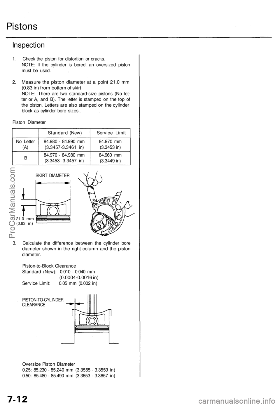
2. Measur e th e pisto n diamete r a t a poin t 21. 0 m m
(0.8 3 in ) fro m botto m of skir t
NOTE : Ther e ar e tw o standard-siz e piston s (N o let -
te r o r A , an d B) . Th e lette r i s stampe d o n th e to p o f
the piston . Letter s ar e als o stampe d o n th e cylinde r
block a s cylinde r bor e sizes .
Pisto n Diamete r
N o Lette r
(A)
B
Standar d (New )
84.98 0 - 84.99 0 m m
(3.3457-3.346 1 in )
84.97 0 - 84.98 0 m m
(3.345 3 -3.345 7 in ) Servic
e Limi t
84.97 0 m m
(3.345 3 in )
84.96 0 m m
(3.344 9 in )
SKIR T DIAMETE R
21.0 mm(0.8 3 in)
3. Calculat e th e differenc e betwee n th e cylinde r bor e
diamete r show n i n th e righ t colum n an d th e pisto n
diameter .
Piston-to-Bloc k Clearanc e
Standar d (New) : 0.01 0 - 0.04 0 m m
(0.0004-0.001 6 in )
Servic e Limit : 0.0 5 m m (0.00 2 in )
PISTON-TO-CYLINDE RCLEARANCE
Oversize Pisto n Diamete r
0.25 : 85.23 0 - 85.24 0 m m (3.355 5 - 3.355 9 in )
0.50 : 85.48 0 - 85.49 0 m m (3.365 3 - 3.365 7 in )
ProCarManuals.com
Page 791 of 1771
• I f measurement s i n an y cylinde r ar e beyon d
oversiz e bor e servic e limit , replac e th e cylinde r
block .
• I f th e bloc k i s t o b e rebored , refe r t o Pisto n
Clearanc e Inspectio n (se e pag e 7-11 ) afte r reboring .
NOTE : Score d o r scratche d cylinde r bore s mus t b e
honed .
Reborin g Limit : 0. 5 m m (0.0 2 in )
2 . Chec k th e to p o f th e cylinde r bloc k fo r warpage .
Measur e alon g th e edge s an d acros s th e cente r a s
shown .
SURFACE S T O B E MEASURE D
Cylinder Bloc k Warpage :
Standar d (New) : 0.0 7 m m (0.00 3 in ) max .
Servic e Limit : 0.1 0 m m (0.00 4 in )
PRECISIO N STRAIGH T EDG E(Commerciall yavailable)
ProCarManuals.com
Page 792 of 1771
Bore Honin g
2.
3.
4 .
Measur e cylinde r bore s a s show n o n pag e 7-12 . I f
th e cylinde r bloc k i s t o b e reused , hon e th e cylin -
der s an d remeasur e th e bores .
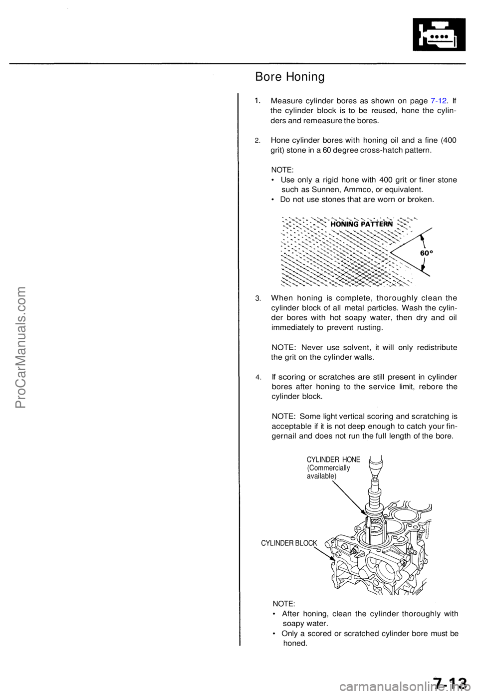
Hon e cylinde r bore s wit h honin g oi l an d a fin e (40 0
grit ) ston e in a 60 degre e cross-hatc h pattern .
NOTE:
• Us e onl y a rigi d hon e wit h 40 0 gri t o r fine r ston e
suc h a s Sunnen , Ammco , o r equivalent .
• D o no t us e stone s tha t ar e wor n o r broken .
Whe n honin g i s complete , thoroughl y clea n th e
cylinde r bloc k o f al l meta l particles . Was h th e cylin -
de r bore s wit h ho t soap y water , the n dr y an d oi l
immediatel y t o preven t rusting .
NOTE : Neve r us e solvent , i t wil l onl y redistribut e
th e gri t o n th e cylinde r walls .
If scorin g o r scratche s ar e stil l presen t i n cylinde r
bores afte r honin g t o th e servic e limit , rebor e th e
cylinde r block .
NOTE : Som e ligh t vertica l scorin g an d scratchin g is
acceptabl e if i t i s no t dee p enoug h t o catc h you r fin -
gernai l an d doe s no t ru n th e ful l lengt h o f th e bore .
CYLINDE R HON E
(Commerciall y
available )
CYLINDE R BLOC K
NOTE:
• Afte r honing , clea n th e cylinde r thoroughl y wit h
soap y water .
• Onl y a score d o r scratche d cylinde r bor e mus t b e
honed .
ProCarManuals.com
Page 799 of 1771
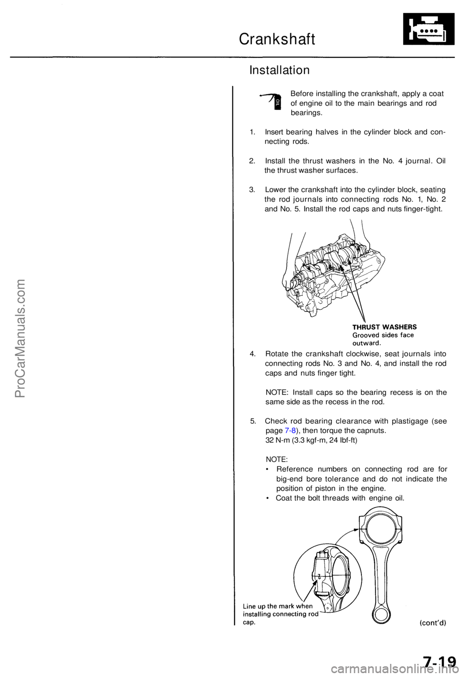
Crankshaft
Installation
Before installin g th e crankshaft , appl y a coa t
o f engin e oi l t o th e mai n bearing s an d ro d
bearings .
1. Inser t bearin g halve s i n th e cylinde r bloc k an d con -
nectin g rods .
2 . Instal l th e thrus t washer s i n th e No . 4 journal . Oi l
th e thrus t washe r surfaces .
3 . Lowe r th e crankshaf t int o th e cylinde r block , seatin g
th e ro d journal s int o connectin g rod s No . 1 , No . 2
an d No . 5 . Instal l th e ro d cap s an d nut s finger-tight .
4 . Rotat e th e crankshaf t clockwise , sea t journal s int o
connectin g rod s No . 3 an d No . 4 , an d instal l th e ro d
cap s an d nut s finge r tight .
NOTE : Instal l cap s s o th e bearin g reces s i s o n th e
sam e sid e a s th e reces s in th e rod .
5 . Chec k ro d bearin g clearanc e wit h plastigag e (se e
pag e 7-8 ), the n torqu e th e capnuts .
3 2 N- m (3. 3 kgf-m , 2 4 Ibf-ft )
NOTE :
• Referenc e number s o n connectin g ro d ar e fo r
big-en d bor e toleranc e an d d o no t indicat e th e
positio n o f pisto n i n th e engine .
• Coa t th e bol t thread s wit h engin e oil .
ProCarManuals.com
Page 800 of 1771
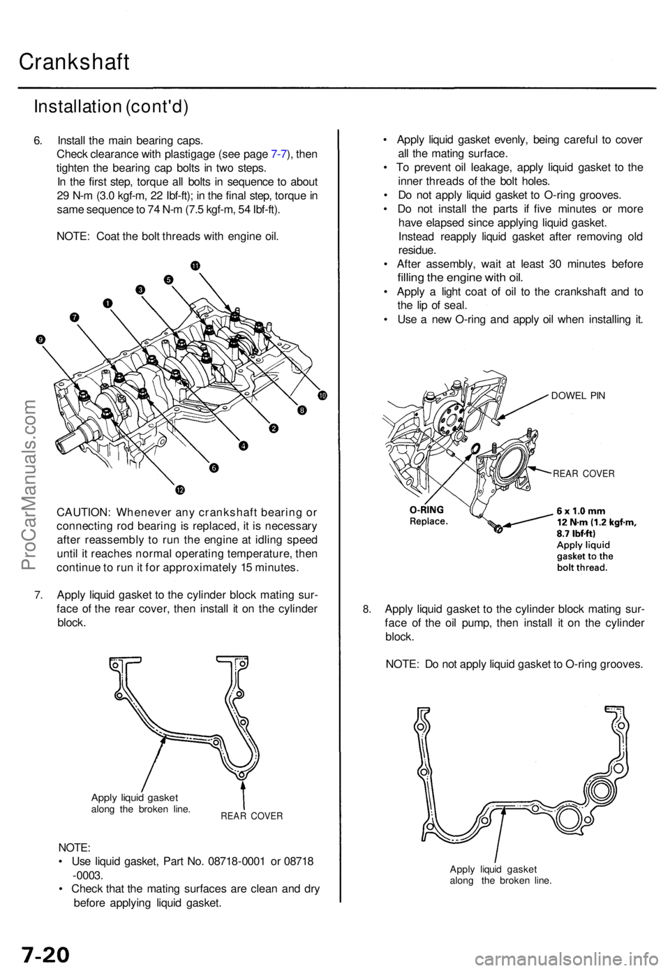
Crankshaft
Installation (cont'd )
6. Instal l th e mai n bearin g caps .
Chec k clearanc e wit h plastigag e (se e pag e 7-7 ), the n
tighte n th e bearin g ca p bolt s i n tw o steps .
I n th e firs t step , torqu e al l bolt s i n sequenc e t o abou t
2 9 N- m (3. 0 kgf-m , 2 2 Ibf-ft) ; i n th e fina l step , torqu e in
sam e sequenc e to 7 4 N- m (7. 5 kgf-m , 5 4 Ibf-ft) .
NOTE : Coa t th e bol t thread s wit h engin e oil .
7.
CAUTION : Wheneve r an y crankshaf t bearin g o r
connectin g ro d bearin g is replaced , i t i s necessar y
afte r reassembl y t o ru n th e engin e a t idlin g spee d
unti l i t reache s norma l operatin g temperature , the n
continu e to ru n it fo r approximatel y 1 5 minutes .
Appl y liqui d gaske t t o th e cylinde r bloc k matin g sur -
fac e o f th e rea r cover , the n instal l i t o n th e cylinde r
block .
Apply liqui d gaske talong th e broke n line .REA R COVE R
NOTE:
• Us e liqui d gasket , Par t No . 0871 8-000 1 o r 0871 8
- 0003 .
• Chec k tha t th e matin g surface s ar e clea n an d dr y
befor e applyin g liqui d gasket .
8.
• Appl y liqui d gaske t evenly , bein g carefu l t o cove r
al l th e matin g surface .
• T o preven t oi l leakage , appl y liqui d gaske t t o th e
inne r thread s o f th e bol t holes .
• D o no t appl y liqui d gaske t t o O-rin g grooves .
• D o no t instal l th e part s i f fiv e minute s o r mor e
hav e elapse d sinc e applyin g liqui d gasket .
Instea d reappl y liqui d gaske t afte r removin g ol d
residue .
• Afte r assembly , wai t a t leas t 3 0 minute s befor e
filling th e engin e wit h oil .
• Appl y a ligh t coa t o f oi l t o th e crankshaf t an d t o
th e li p o f seal .
• Us e a ne w O-rin g an d appl y oi l whe n installin g it .
DOWE L PI N
REA R COVE R
Apply liqui d gaske t t o th e cylinde r bloc k matin g sur -
fac e o f th e oi l pump , the n instal l i t o n th e cylinde r
block .
NOTE : D o no t appl y liqui d gaske t t o O-rin g grooves .
Apply liqui d gaske t
alon g th e broke n line .
ProCarManuals.com
Page 801 of 1771
NOTE:
• Appl y a ligh t coa t o f oi l t o th e crankshaf t an d t o th e
li p o f seal .
• Us e ne w O-ring s an d appl y oi l whe n installin g them .
9 . Instal l th e oi l screen .
6 x 1. 0 m m12 N- m (1. 2 kgf-m , 8. 7 Ibf-ft )
GASKE TReplace .
OIL SCREE N
O-RING S
Replace .
6 x 1. 0 m m12 N- m (1. 2 kgf-m , 8. 7 Ibf-ft )Apply liqui d gaske t t oth e bol t thread .
DOWEL PI N
OI L PUM P
10. Appl y liqui d gaske t t o th e cylinde r block , the n instal l
the oi l pan .
Appl y liqui d gaske talong th e broke n line .
11. Torqu e th e oil pa n bolt s an d nut s a s shown .
8 x 1.2 5 mm
22 N- m (2. 2 kgf-m , 1 6 Ibf-ft )
OIL PA N BOL T TORQU E SEQUENC E
12. Instal l th e oi l pa n inne r pipe , the n instal l th e se t
plate .
O-RING S
Replace .
Clean whe n installing .
OIL PA NINNE R PIP E
O-RIN GReplace .Clean whe n installing .
SET PLAT E
6 x 1. 0 m m12 N- m (1. 2 kgf-m , 8. 7 Ibf-ft )
CYLINDE RBLOCK
ProCarManuals.com