Page 750 of 1771
Cylinder Hea d
Remova l
Engine remova l i s no t require d fo r thi s procedure .
Mak e sur e jack s an d safet y stand s ar e
place d properl y an d hois t bracket s ar e attache d to cor -
rec t positio n o n th e engine .
CAUTION :
• Us e fende r cover s t o avoi d damagin g painte d sur -
faces .
• Unplu g th e wirin g connector s carefull y whil e holdin g
th e connecto r portio n to avoi d damage .
• T o avoi d damagin g th e cylinde r head , wai t unti l th e
engin e coolan t temperatur e drop s belo w 100° F
(38°C ) befor e loosenin g th e retainin g bolts .
NOTE :
• Mar k al l wirin g an d hose s t o avoi d misconnection .
Also , b e sur e tha t the y d o no t contac t othe r wirin g o r
hoses , o r interfer e wit h othe r parts .
• Inspec t th e timin g bel t befor e removin g th e cylinde r
head .
• Tur n th e crankshaf t pulle y s o tha t th e No . 1 pisto n i s
a t to p dea d cente r (se e pag e 6-12 ).
1 . Mak e sur e yo u hav e th e anti-thef t cod e fo r th e radio ,
the n writ e dow n th e frequencie s fo r th e radio' s pre -
se t buttons .
2 . Disconnec t th e negativ e termina l fro m th e battery .
3 . Drai n th e engin e coolan t (se e pag e 10-5 ).
Remov e th e radiato r cap to spee d draining .
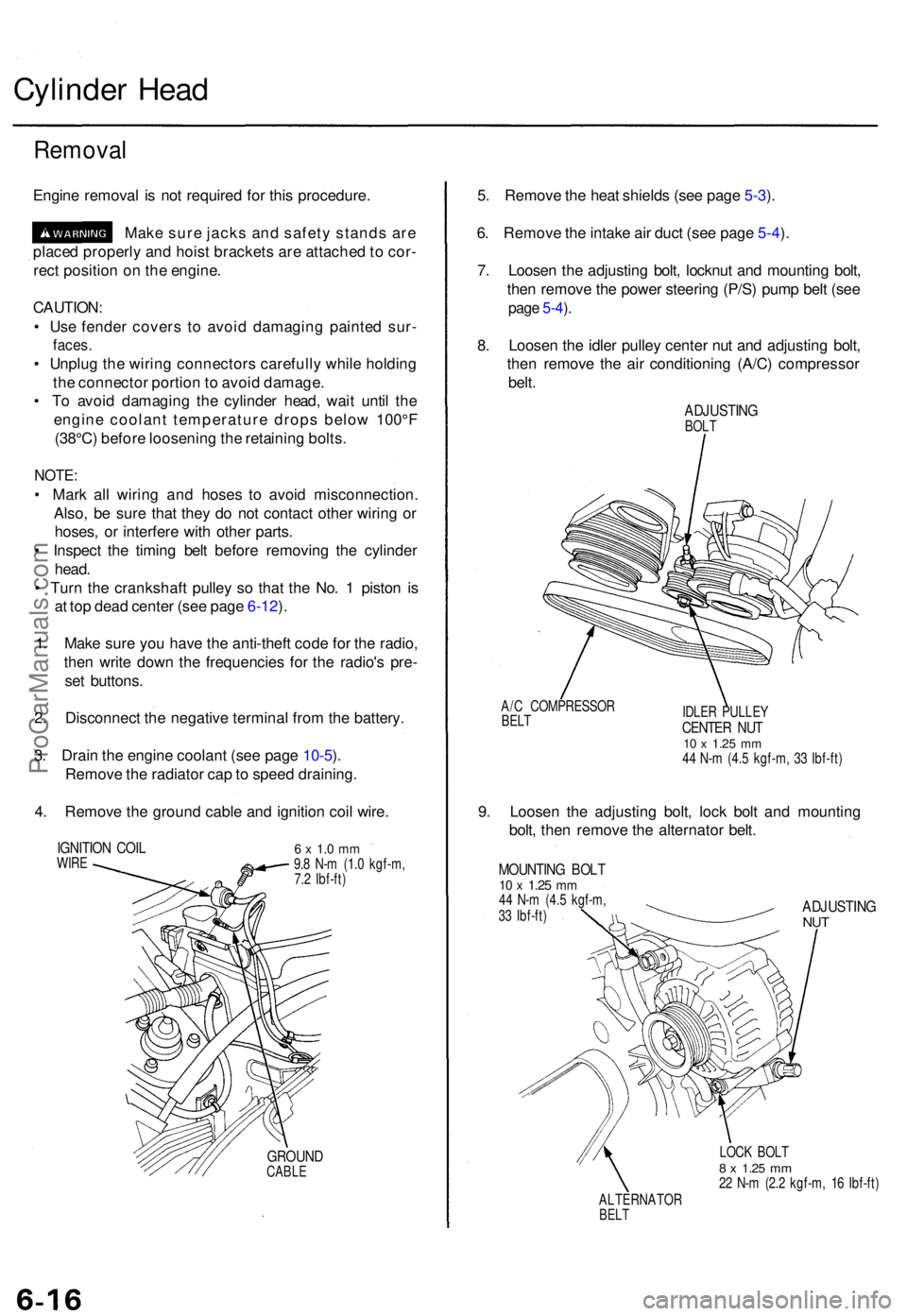
4 . Remov e th e groun d cabl e an d ignitio n coi l wire .
IGNITIO N COI LWIRE6 x 1. 0 m m9.8 N- m (1. 0 kgf-m ,
7. 2 Ibf-ft )
GROUN DCABLE
5. Remov e th e hea t shield s (se e pag e 5-3 ).
6 . Remov e th e intak e ai r duc t (se e pag e 5-4 ).
7 . Loose n th e adjustin g bolt , locknu t an d mountin g bolt ,
the n remov e th e powe r steerin g (P/S ) pum p bel t (se e
page 5-4 ).
8 . Loose n th e idle r pulle y cente r nu t an d adjustin g bolt ,
the n remov e th e ai r conditionin g (A/C ) compresso r
belt .
ADJUSTIN GBOLT
A/ C COMPRESSO R
BELTIDLE R PULLE YCENTER NU T10 x 1.2 5 mm44 N- m (4. 5 kgf-m , 3 3 Ibf-ft )
9. Loose n th e adjustin g bolt , loc k bol t an d mountin g
bolt , the n remov e th e alternato r belt .
MOUNTIN G BOL T10 x 1.2 5 mm44 N- m (4. 5 kgf-m ,
3 3 Ibf-ft )ADJUSTIN GNUT
LOC K BOL T8 x 1.2 5 mm22 N- m (2. 2 kgf-m , 1 6 Ibf-ft )
ALTERNATO R
BELT
ProCarManuals.com
Page 751 of 1771
10. Remov e th e throttl e cabl e b y loosenin g th e locknut ,
then sli p th e cabl e en d ou t o f th e accelerato r linkag e
(see pag e 5-5 ).
11 . Remov e th e brak e booste r vacuu m hose , evaporativ e
emissio n (EVAP ) contro l caniste r hos e an d vacuu m
hose s (se e pag e 5-5 ).
12 . Reliev e fue l pressur e (se e sectio n 11 ).
D o no t smok e whil e workin g o n th e fue l
system . Kee p ope n flam e o r spark s awa y fro m th e
wor k area . Drai n fue l onl y int o a n approve d container .
13 . Remov e th e fue l fee d hos e an d fue l retur n hos e (se e
pag e 5-6 ).
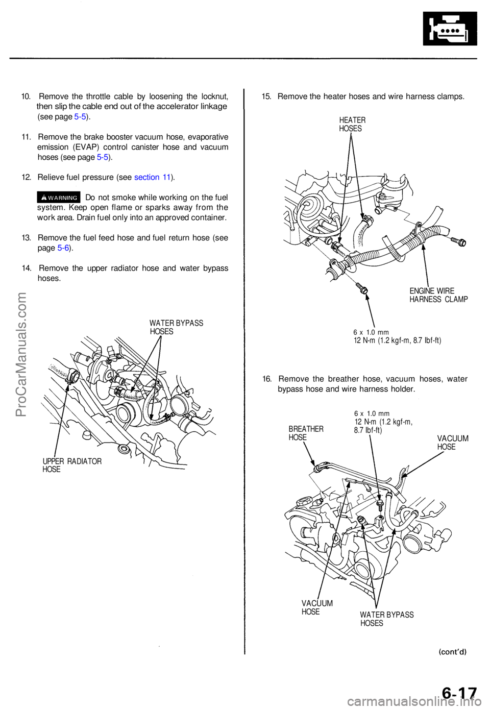
14 . Remov e th e uppe r radiato r hos e an d wate r bypas s
hoses.
WATE R BYPAS SHOSES
UPPER RADIATO R
HOS E
15. Remov e th e heate r hose s an d wir e harnes s clamps .
HEATERHOSES
ENGIN E WIR EHARNES S CLAM P
6 x 1. 0 m m12 N- m (1. 2 kgf-m , 8. 7 Ibf-ft )
16. Remov e th e breathe r hose , vacuu m hoses , wate r
bypas s hos e an d wir e harnes s holder .
BREATHE RHOSE
6 x 1. 0 m m12 N- m (1. 2 kgf-m ,
8. 7 Ibf-ft )
VACUU MHOSE
VACUU MHOSE
WATER BYPAS S
HOSE S
ProCarManuals.com
Page 753 of 1771
21. Remov e th e intak e manifold .
8 x 1.2 5 mm22 N- m (2. 2 kgf-m , 1 6 Ibf-ft )
GASKE T
Replace .
INTAKEMANIFOL D
8 x 1.2 5 mm22 N- m (2. 2 kgf-m , 1 6 Ibf-ft )
22. Remov e th e wir e harnes s covers , the n disconnec t
th e primar y heate d oxyge n (HO2S ) connector .
PRIMARY HO2 S
CONNECTO R
WIR E HARNES S
COVER S 8 x 1.2 5 m m
2 2 N- m (2. 2 kgf-m , 1 6 Ibf-ft )
23. Remov e th e self-lockin g nu t an d exhaus t manifol d
brackets .
EXHAUS T MANIFOL DBRACKETS
24. Remov e th e exhaus t manifol d (se e pag e 9-4 ).
25 . Remov e th e groun d cable s an d cylinde r hea d cover .
GROUN DCABLES
CYLINDE R HEA DCOVE R
WASHE R
SELF-LOCKIN G NU T10 x 1.2 5 mm54 N- m (5. 5 kgf-m , 4 0 Ibf-ft )
Replace .
GASKETReplace .8 x 1.2 5 mm27 N- m (2. 8 kgf-m ,20 Ibf-ft )
ProCarManuals.com
Page 758 of 1771
7. If the camshaft-to-holder oil clearance is out of tol-
erance:
— And the camshaft has already been replaced, you
must replace the cylinder head.
— If the camshaft has not been replaced, first check
the total runout with the camshaft supported on
V-blocks.
Camshaft Total Runout:
Standard (New): 0.03 mm (0.001 in) max.
Service Limit: 0.04 mm (0.002 in)
Rotate camshaft
while measuring.
If the total runout of the camshaft is within toler-
ance, replace the cylinder head.
If the total runout is out of tolerance, replace the
camshaft and recheck. If the oil clearance is still
out of tolerance, replace the cylinder head.
8. Check the cam lobe height wear.
Cam Lobe Height Standard (New):
INTAKE: 39.203 mm (1.5434 in)
EXHAUST: 38.875 mm (1.5305 in)
Check this area for wear.ProCarManuals.com
Page 767 of 1771
Valve Guide s
Reamin g
NOTE: Fo r ne w valv e guide s only .
1 . Coa t bot h th e reame r an d valv e guid e wit h cuttin g
oil.
2. Rotat e th e reame r clockwis e th e ful l lengt h o f th e
valv e guid e bore .
3 . Continu e t o rotat e th e reame r clockwis e whil e remov -
in g i t fro m th e bore .
4 . Thoroughl y was h th e guid e i n detergen t an d wate r
t o remov e an y cuttin g residue .
5 . Chec k th e clearanc e wit h a valv e (se e pag e 6-27 ).
— Verif y tha t th e valv e slide s i n th e valv e guid e
withou t exertin g pressure .
VALVE GUID E
REAMER , 5. 5 m m
07HA H - PJ7010 B
ProCarManuals.com
Page 770 of 1771
Camshaft/Rocker Arms and
Camshaft Seal
Installation
CAUTION:
• Make sure that all rockers are in alignment with their
valves when torquing the rocker assembly bolts.
• Valve locknuts should be loosened and adjusting
screws backed off before installation.
• To prevent the rocker arm assembly from coming
apart, leave the camshaft holder bolts in the holes.
1. After wiping down the camshaft and journals in the
cylinder head, lubricate both surfaces and install the
camshaft.
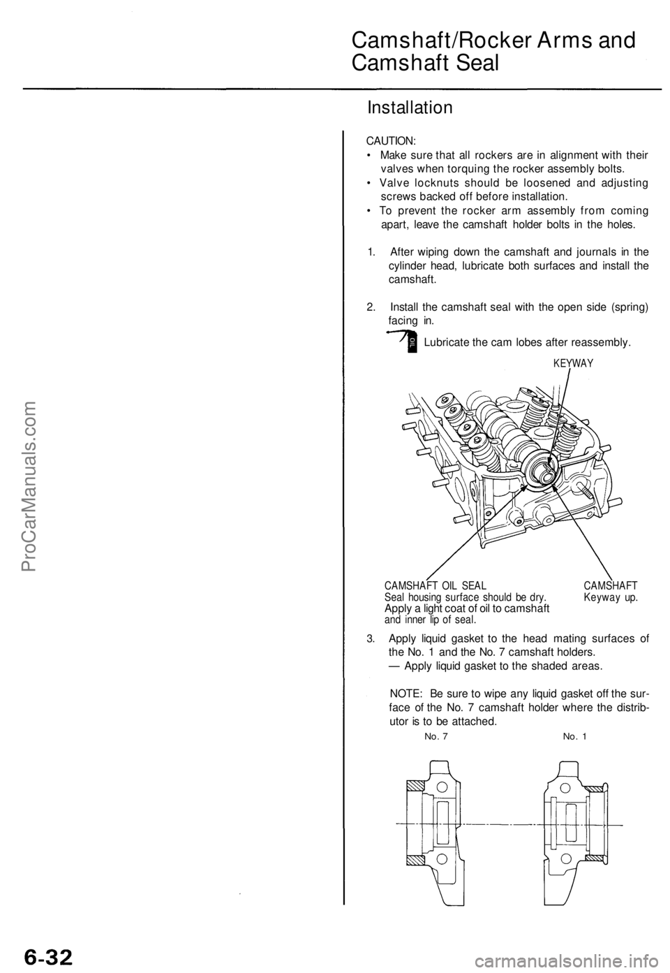
2. Install the camshaft seal with the open side (spring)
facing in.
Lubricate the cam lobes after reassembly.
KEYWAY
3.
CAMSHAFT OIL SEAL CAMSHAFT
Seal housing surface should be dry. Keyway up.
Apply a light coat of oil to camshaft
and inner lip of seal.
Apply liquid gasket to the head mating surfaces of
the No. 1 and the No. 7 camshaft holders.
— Apply liquid gasket to the shaded areas.
NOTE: Be sure to wipe any liquid gasket off the sur-
face of the No. 7 camshaft holder where the distrib-
utor is to be attached.
No. 7 No. 1ProCarManuals.com
Page 773 of 1771
Cylinder Hea d
Installatio n (cont'd )
3. Tur n th e camshaf t unti l it s keywa y i s facin g u p (No . 1
pisto n TDC) .
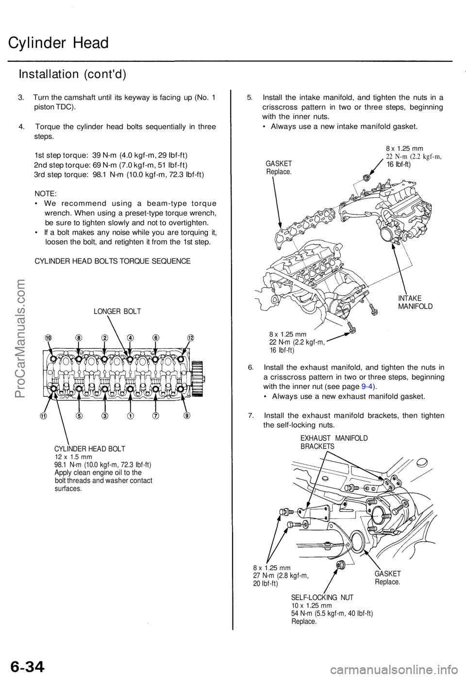
4 . Torqu e th e cylinde r hea d bolt s sequentiall y i n thre e
steps .
1s t ste p torque : 3 9 N- m (4. 0 kgf-m , 2 9 Ibf-ft )
2n d ste p torque : 6 9 N- m (7. 0 kgf-m , 5 1 Ibf-ft )
3r d ste p torque : 98. 1 N- m (10. 0 kgf-m , 72. 3 Ibf-ft )
NOTE :
• W e recommen d usin g a beam-typ e torqu e
wrench . Whe n usin g a preset-typ e torqu e wrench ,
b e sur e t o tighte n slowl y an d no t t o overtighten .
• I f a bol t make s an y nois e whil e yo u ar e torquin g it ,
loose n th e bolt , an d retighte n it fro m th e 1s t step .
CYLINDE R HEA D BOLT S TORQU E SEQUENC E
LONGER BOL T
CYLINDE R HEA D BOL T
12 x 1. 5 m m98. 1 N- m (10. 0 kgf-m , 72. 3 Ibf-ft )Apply clea n engin e oi l t o th ebol t thread s an d washe r contac tsurfaces .
5.
6.
7 .
Instal l th e intak e manifold , an d tighte n th e nut s i n a
crisscros s patter n i n tw o o r thre e steps , beginnin g
wit h th e inne r nuts .
• Alway s us e a ne w intak e manifol d gasket .
GASKE TReplace .
8 x 1.2 5 mm22 N- m (2. 2 kgf-m ,16 Ibf-ft )
INTAK EMANIFOL D
8 x 1.2 5 mm22 N- m (2. 2 kgf-m ,16 Ibf-ft )
Install th e exhaus t manifold , an d tighte n th e nut s i n
a crisscros s patter n in tw o o r thre e steps , beginnin g
wit h th e inne r nu t (se e pag e 9-4 ).
• Alway s us e a ne w exhaus t manifol d gasket .
Instal l th e exhaus t manifol d brackets , the n tighte n
th e self-lockin g nuts .
EXHAUS T MANIFOL DBRACKETS
8 x 1.2 5 mm27 N- m (2. 8 kgf-m ,
2 0 Ibf-ft )GASKE TReplace .
SELF-LOCKIN G NU T10 x 1.2 5 mm54 N- m (5. 5 kgf-m , 4 0 Ibf-ft )
Replace .
ProCarManuals.com
Page 779 of 1771
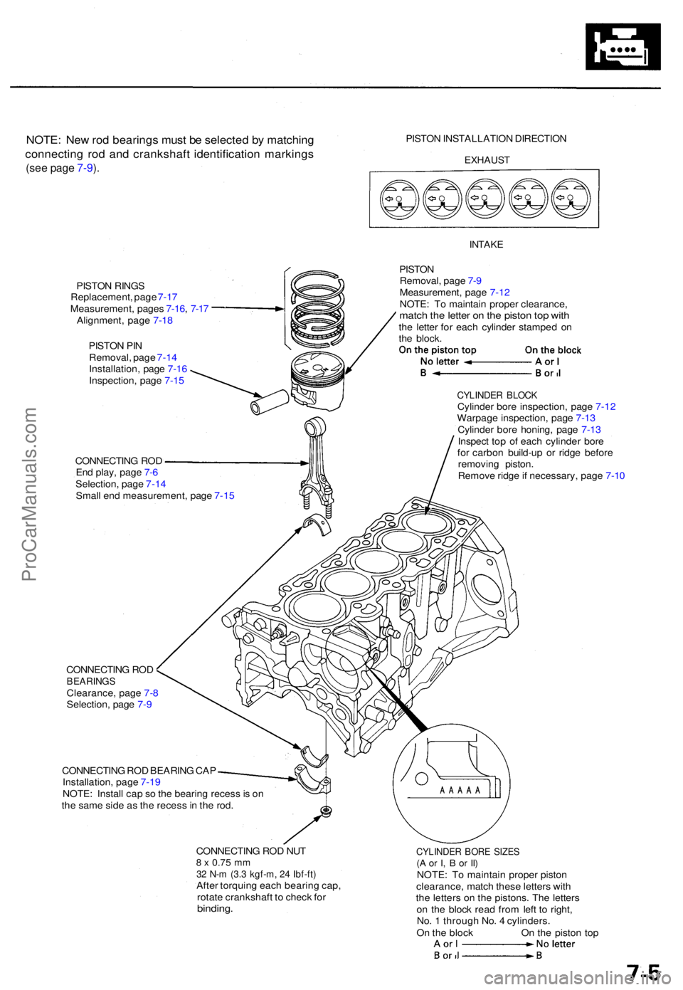
NOTE: Ne w ro d bearing s mus t b e selecte d b y matchin g
connectin g ro d an d crankshaf t identificatio n marking s
(see pag e 7-9 ).
PISTO N INSTALLATIO N DIRECTIO N
EXHAUST
PISTON RING S
Replacement , pag e 7-1 7
Measurement , page s 7-16 , 7-1 7
Alignment , pag e 7-1 8
PISTO N PI N
Removal , pag e 7-1 4
Installation , pag e 7-1 6
Inspection , pag e 7-1 5
INTAK E
PISTON
Removal , pag e 7- 9
Measurement , pag e 7-1 2
NOTE : T o maintai n prope r clearance ,
match th e lette r o n th e pisto n to p wit hthe lette r fo r eac h cylinde r stampe d o n
th e block .
CONNECTIN G RO D
En d play , pag e 7- 6
Selection , pag e 7-1 4
Smal l en d measurement , pag e 7-1 5
CYLINDE R BLOC KCylinde r bor e inspection , pag e 7-1 2
Warpag e inspection , pag e 7-1 3
Cylinde r bor e honing , pag e 7-1 3
Inspec t to p o f eac h cylinde r bor e
fo r carbo n build-u p o r ridg e befor e
removin g piston .
Remov e ridg e if necessary , pag e 7-1 0
CONNECTIN G RO D
BEARING SClearance , pag e 7- 8
Selection , pag e 7-9
CONNECTIN G RO D BEARIN G CA P
Installation , pag e 7-1 9
NOTE : Instal l ca p s o th e bearin g reces s is o n
th e sam e sid e a s th e reces s in th e rod .
CONNECTIN G RO D NU T
8 x 0.7 5 mm32 N- m (3. 3 kgf-m , 2 4 Ibf-ft )After torquin g eac h bearin g cap ,
rotat e crankshaf t t o chec k fo r
binding .
CYLINDE R BOR E SIZE S(A o r I , B or Il )NOTE : T o maintai n prope r pisto n
clearance , matc h thes e letter s wit h
th e letter s o n th e pistons . Th e letter s
o n th e bloc k rea d fro m lef t t o right ,
No . 1 throug h No . 4 cylinders .
O n th e bloc k O n th e pisto n to p
ProCarManuals.com