Page 550 of 1771
Hood
Replacemen t (cont'd )
2. Disconnec t th e washe r tub e a t th e L-joint , an d detac h
th e cli p fro m th e hoo d hinge .
3 . Remov e th e suppor t stru t an d bolt s o n eac h sid e
whil e holdin g th e hood , the n remov e th e hood .
NOTE : I f necessary , remov e th e suppor t strut .
SUPPOR T
STRU T
SUPPOR T
STRU T
SUPPORT
STRU T
WASHE RTUBE
L-JOIN THOOD
HING E
8 x 1.2 5 mm22 N- m (2. 2 kgf-m ,
1 6 Ibf-ft )
4. Installatio n i s th e revers e o f th e remova l procedure .
NOTE:
If necessary , replac e an y damage d clips .
Mak e sur e th e hoo d open s properl y an d lock s
securely .
Adjust th e hoo d alignment .
Adjus t th e ai m o f th e windshiel d washe r nozzle s
(se e pag e 20-14 ).
CLI P
HOO D
WASHE
R
TUB E HOO
D
6 x 1. 0 m m9.8 N- m (1. 0 kgf-m ,
7. 2 Ibf-ft )6 x 1. 0 m m9.8 N- m (1. 0 kgf-m ,
7. 2 Ibf-ft )
ProCarManuals.com
Page 560 of 1771
Illustrated Inde x
EXPANSIO N VALV E
SERVIC E VALV E
(LOW-PRESSUR E SIDE )
CONDENSE R
Replacement , pag e 22-2 5
A/ C PRESSUR E SWITC H
Whe n th e refrigeran t pressur e i s belo w 20 0 kP a (2. 0 kgf/cm
2,
2 8 psi ) du e to refrigeran t leakag e o r abov e 3,20 0 kP a (3 2 kgf/cm2,
45 5 psi ) du e t o refrigeran t blockage , th e A/ C pressur e switc h
opens th e circui t t o th e A/ C switc h an d stop s th e ai r conditionin gto protec t th e compressor .
COMPRESSO RReplacement, pag e 22-2 2
RECEIVER/DRYE R
SERVICE VALV E
(HIGH-PRESSUR E SIDE )
HEATER/EVAPORATOR/BLOWE R UNITHEATE R UNI T
Replacement , pag e 22-6 3
Heate r Cor e Replacement , pag e 22-6 5
EVAPORATO RReplacement, pag e 22-5 8
Overhaul , pag e 22-6 0
BLOWE R UNI T
Replacement , pag e 22-6 1
Overhaul , pag e 22-6 2
Replacement, pag e 22-6 3
Clutc h Inspection , pag e 22-7 5
Clutc h Overhaul , pag e 22-7 6
Relie f Valv e Replacement , pag e 22-7 7
ProCarManuals.com
Page 592 of 1771

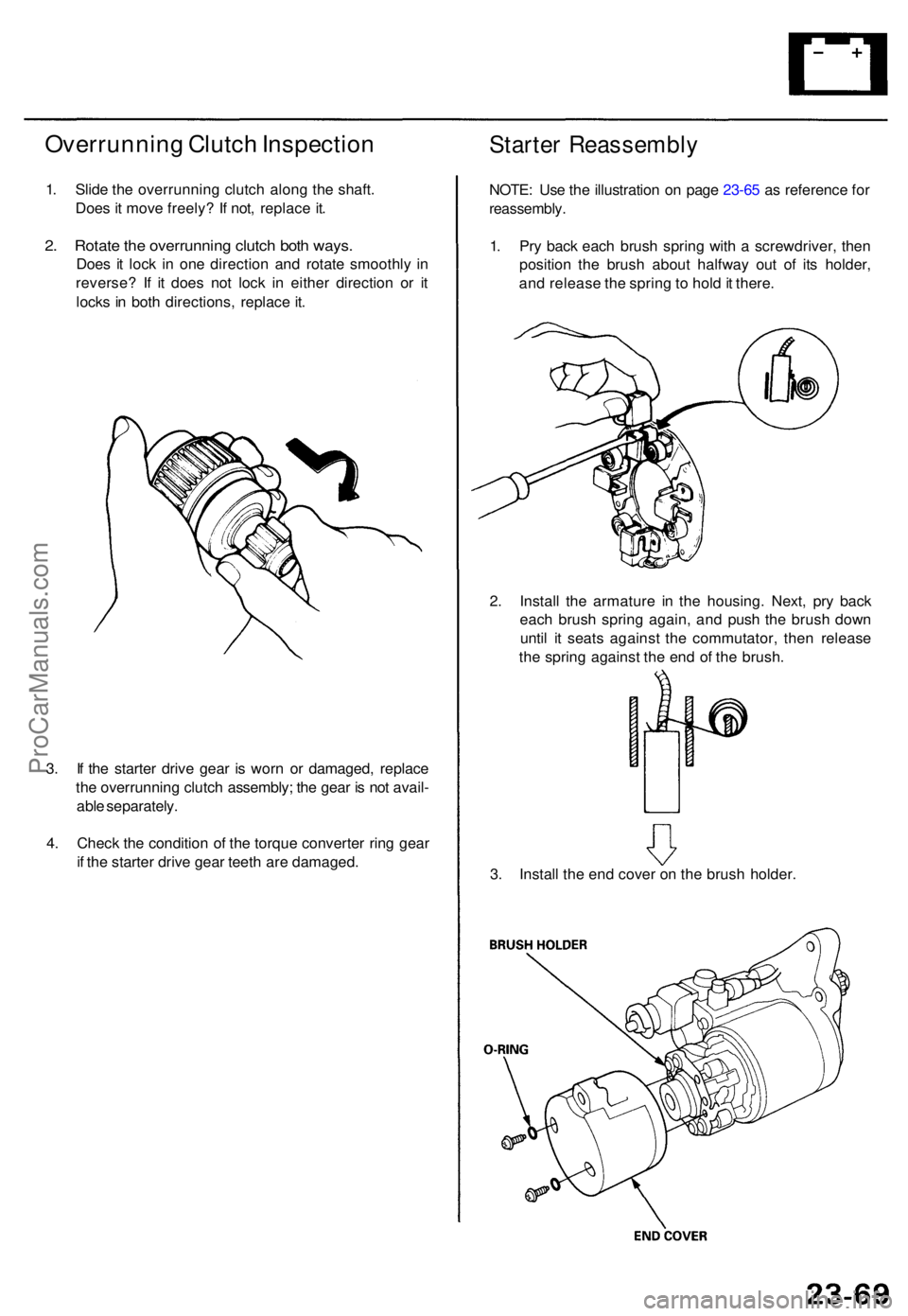
Overrunning Clutc h Inspectio n
1. Slid e th e overrunnin g clutc h alon g th e shaft .
Doe s i t mov e freely ? I f not , replac e it .
2. Rotat e th e overrunnin g clutc h bot h ways .
Does i t loc k i n on e directio n an d rotat e smoothl y i n
reverse ? I f i t doe s no t loc k i n eithe r directio n o r i t
lock s i n bot h directions , replac e it .
Starte r Reassembl y
NOTE: Us e th e illustratio n o n pag e 23-6 5 a s referenc e fo r
reassembly .
1. Pr y bac k eac h brus h sprin g wit h a screwdriver , the n
positio n th e brus h abou t halfwa y ou t o f it s holder ,
an d releas e th e sprin g to hol d it there .
2 . Instal l th e armatur e i n th e housing . Next , pr y bac k
eac h brus h sprin g again , an d pus h th e brus h dow n
unti l i t seat s agains t th e commutator , the n releas e
th e sprin g agains t th e en d o f th e brush .
3 . Instal l th e en d cove r o n th e brus h holder .
3
. I f th e starte r driv e gea r i s wor n o r damaged , replac e
th e overrunnin g clutc h assembly ; th e gea r i s no t avail -
abl e separately .
4 . Chec k th e conditio n o f th e torqu e converte r rin g gea r
i f th e starte r driv e gea r teet h ar e damaged .
ProCarManuals.com
Page 606 of 1771
Alternator Replacemen t
1. Mak e sur e yo u hav e th e anti-thef t cod e fo r th e radio ,
the n writ e dow n th e frequencie s fo r th e radio' s pre -
set buttons .
2. Disconnec t th e batter y negativ e cable , the n discon -
nec t th e positiv e cable .
3 . Remov e th e lowe r mountin g bolt , adjustin g loc k
bol t an d adjustin g rod , the n remov e th e bel t fro m
th e pulley . 4
. A s show n i n th e illustration , rotat e th e alternato r 9 0
degree s counterclockwis e an d pul l i t ou t towar d you .
5 . Disconnec t th e 4 P connecto r an d th e harnes s cli p
bracket , the n remov e th e termina l nu t an d th e BL K
wir e fro m th e B terminal . Tak e ou t th e alternator .
6 . Instal l i n th e revers e orde r o f removal .
7 . Adjus t th e alternato r bel t tensio n (se e pag e 23-89 ).
8 . Ente r th e anti-theft code fo r th e radio , the n ente r th e
customer' s radi o statio n presets .
ProCarManuals.com
Page 607 of 1771
STATOR/DRIVE EN D HOUSIN G
Test , pag e 23-8 8
ROTO
R
Test , pag e 23-8 8
Chargin g Syste m
Alternato r Overhau l
NOTE: D o no t remov e th e pulle y unles s th e fron t bear -
in g need s replacement .
T o loose n th e pulle y locknut , us e th e tool s a s shown . I f
necessary , us e a n impac t wrench .
BRUSH ASSEMBL Y
Inspection , pag e 23-8 7
RECTIFIE R ASSEMBL Y
Test , pag e 23-8 7
ProCarManuals.com
Page 615 of 1771

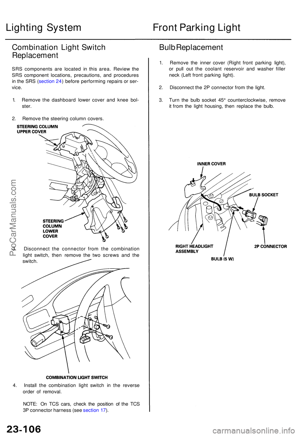
4. Instal l th e combinatio n ligh t switc h i n th e revers e
orde r o f removal .
NOTE : O n TC S cars , chec k th e positio n o f th e TC S
3 P connecto r harnes s (se e sectio n 17 ).
Lightin g Syste m
Combinatio n Ligh t Switc h
Replacemen t
SRS component s ar e locate d i n thi s area . Revie w th e
SR S componen t locations , precautions , an d procedure s
i n th e SR S (sectio n 24 ) befor e performin g repair s o r ser -
vice .
1 . Remov e th e dashboar d lowe r cove r an d kne e bol -
ster .
2 . Remov e th e steerin g colum n covers .
3 . Disconnec t th e connecto r fro m th e combinatio n
ligh t switch , the n remov e th e tw o screw s an d th e
switch .
Front Parkin g Ligh t
Bulb Replacemen t
1. Remov e th e inne r cove r (Righ t fron t parkin g light) ,
o r pul l ou t th e coolan t reservoi r an d washe r fille r
nec k (Lef t fron t parkin g light) .
2 . Disconnec t th e 2 P connecto r fro m th e light .
3 . Tur n th e bul b socke t 45 ° counterclockwise , remov e
i t fro m th e ligh t housing , the n replac e th e bulb .
ProCarManuals.com
Page 621 of 1771

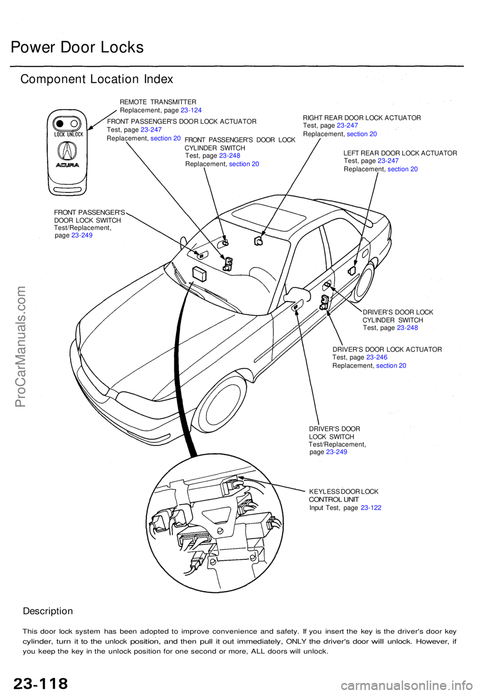
Power Doo r Lock s
Componen t Locatio n Inde x
REMOT E TRANSMITTE R
Replacement , pag e 23-12 4
FRON T PASSENGER' S DOO R LOC K ACTUATO R RIGH
T REA R DOO R LOC K ACTUATO R
FRONT PASSENGER' SDOOR LOC K SWITC H
DRIVER'S DOO R LOC K
CYLINDE R SWITC H
DRIVER' S DOO R LOC K ACTUATO R
LEF
T REA R DOO R LOC K ACTUATO R
DRIVER' S DOO R
LOC K SWITC H
KEYLES S DOO R LOC K
CONTRO L UNI TInpu t Test , pag e 23-12 2
Descriptio n
This doo r loc k syste m ha s bee n adopte d t o improv e convenienc e an d safety . I f yo u inser t th e ke y i s th e driver' s doo r ke y
cylinder , turn it t o th e unloc k position , and the n pull it ou t immediately , ONLY the driver' s door will unlock . However , if
yo u kee p th e ke y i n th e unloc k positio n fo r on e secon d o r more , AL L door s wil l unlock .
FRONT PASSENGER' S DOO R LOC K
CYLINDE R SWITC H
Test
, pag e 23- 247
Replacement , section 20
Test /Replacement ,
pag e 23-24 9 Test
, pag e 23-24 8
Replacement , section 20 Test
, pag e 23-247
Replacement , section 20
Test , pag e 23-247
Replacement , section 20
Test , pag e 23-24 8
Test , pag e 23-24 6
Replacement , section 20
Test/Replacement ,
pag e 23-249
ProCarManuals.com
Page 622 of 1771
Troubleshooting
NOTE: Th e number s i n th e tabl e sho w th e troubleshootin g sequence .
CAUTION : T o preven t damag e to th e motor , appl y batter y voltag e onl y momentarily .
NOTE:
• Whe n th e remot e transmitte r butto n i s presse d th e firs t time , onl y th e driver' s doo r wil l unlock . Whe n th e butto n i s
presse d th e secon d time , al l th e door s wil l unlock .
• Th e door s wil l reloc k automaticall y afte r 2 0 second s i f a doo r i s no t opened , o r th e ke y i s ou t o f th e ignitio n switch .
• Th e keyles s entr y syste m wil l no t loc k th e door s whe n th e ke y i s i n th e ignitio n switch .
ProCarManuals.com