1995 ACURA TL lock
[x] Cancel search: lockPage 475 of 1771
Disassembly
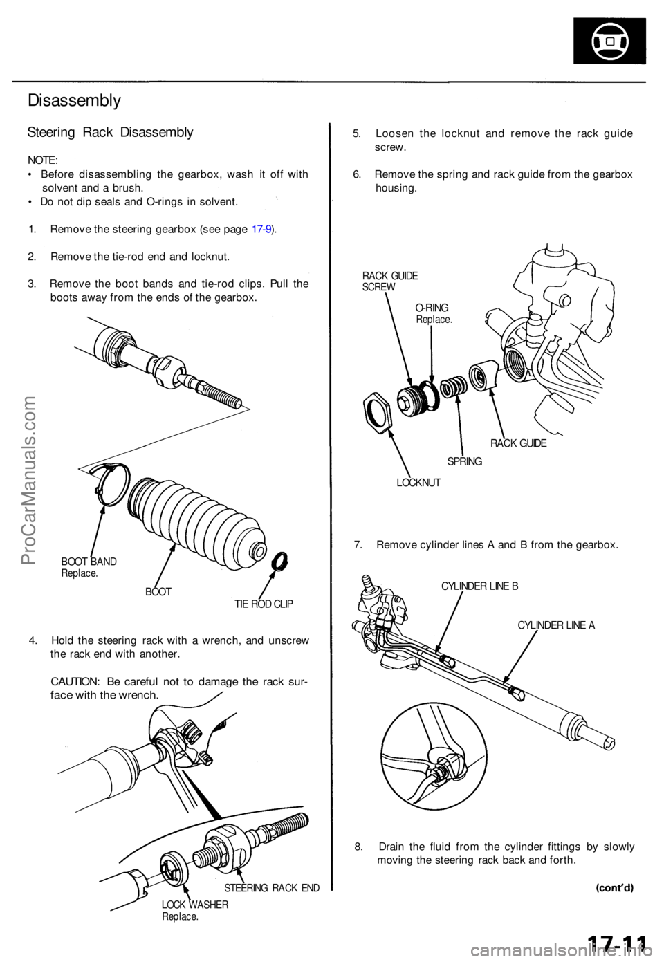
Steering Rac k Disassembl y
NOTE:
• Befor e disassemblin g th e gearbox , was h i t of f wit h
solven t an d a brush .
• D o no t di p seal s an d O-ring s i n solvent .
1 . Remov e th e steerin g gearbo x (se e pag e 17-9 ).
2 . Remov e th e tie-ro d en d an d locknut .
3 . Remov e th e boo t band s an d tie-ro d clips . Pul l th e
boot s awa y fro m th e end s o f th e gearbox .
BOOT BAN DReplace .
BOOTTIE RO D CLI P
4. Hol d th e steerin g rac k wit h a wrench , an d unscre w
th e rac k en d wit h another .
CAUTION : B e carefu l no t t o damag e th e rac k sur -
face wit h th e wrench .
STEERIN G RAC K EN D
LOC K WASHE RReplace.
5. Loose n th e locknu t an d remov e th e rac k guid e
screw .
6 . Remov e th e sprin g an d rac k guid e fro m th e gearbo x
housing .
RACK GUID ESCRE W
RACK GUID E
SPRIN G
LOCKNU T
7. Remov e cylinde r line s A an d B fro m th e gearbox .
CYLINDER LIN E B
CYLINDE R LIN E A
8. Drai n th e flui d fro m th e cylinde r fitting s b y slowl y
movin g th e steerin g rac k bac k an d forth .
O-RIN GReplace .
ProCarManuals.com
Page 479 of 1771
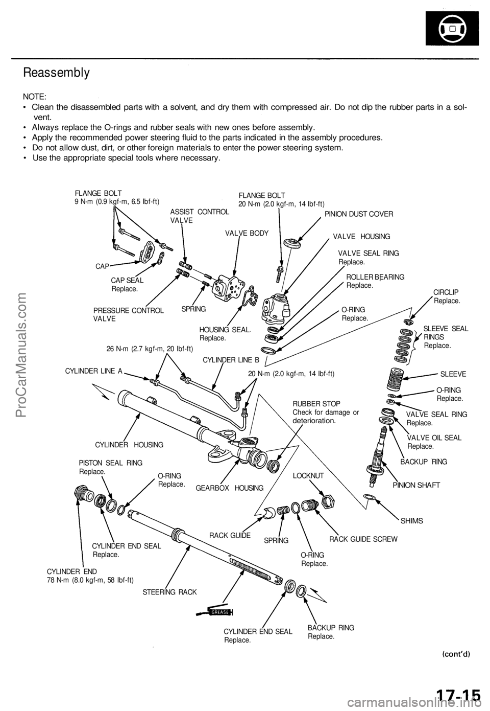
Reassembly
NOTE:
• Clean the disassembled parts with a solvent, and dry them with compressed air. Do not dip the rubber parts in a sol-
vent.
• Always replace the O-rings and rubber seals with new ones before assembly.
• Apply the recommended power steering fluid to the parts indicated in the assembly procedures.
• Do not allow dust, dirt, or other foreign materials to enter the power steering system.
• Use the appropriate special tools where necessary.
FLANGE BOLT
9 N-m (0.9 kgf-m, 6.5 Ibf-ft)
FLANGE BOLT
20 N-m (2.0 kgf-m, 14 Ibf-ft)
CAP
PINION DUST COVER
VALVE HOUSING
26 N-m (2.7 kgf-m, 20 Ibf-ft)
CYLINDER LINE A
VALVE OIL SEAL
Replace.
SHIMS
CYLINDER END
78 N-m (8.0 kgf-m, 58 Ibf-ft)
CYLINDER END SEAL
Replace.
BACKUP RING
Replace.
CAP SEAL
Replace.
PRESSURE CONTROL
VALVE
SPRING
HOUSING SEAL
Replace.
CYLINDER LINE B
VALVE BODY
ASSIST CONTROL
VALVE
VALVE SEAL RING
Replace.
ROLLER BEARING
Replace.
O-RING
Replace.
SLEEVE SEAL
RINGS
Replace.
CIRCLIP
Replace.
SLEEVE
20 N-m (2.0 kgf-m, 14 Ibf-ft)
BACKUP RING
PINION SHAFT
LOCKNUT
RACK GUIDE SCREW
O-RING
Replace.
SPRING
RACK GUIDE
STEERING RACK
CYLINDER END SEAL
Replace.
PISTON SEAL RING
Replace.
CYLINDER HOUSING
GEARBOX HOUSING
O-RING
Replace.
RUBBER STOP
Check for damage or
deterioration.
VALVE SEAL RING
Replace.
O-RING
Replace.ProCarManuals.com
Page 484 of 1771
Steering Gearbo x
Reassembl y (cont'd )
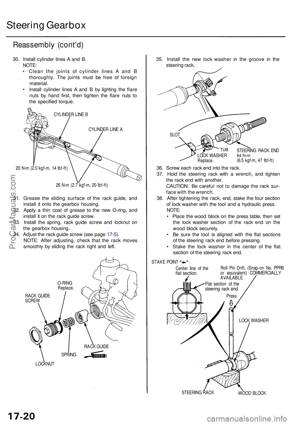
30. Instal l cylinde r line s A an d B .
NOTE :
• Clea n th e joint s o f cylinde r line s A an d B
thoroughly . Th e joint s mus t b e fre e o f foreig n
material .
• Instal l cylinde r line s A an d B by lightin g th e flar e
nut s b y han d first , the n tighte n th e flar e nut s t o
th e specifie d torque .
CYLINDE R LIN E B
CYLINDE R LIN E A
2 0 N- m (2. 0 kgf-m , 1 4 Ibf-ft )
2 6 N- m (2. 7 kgf-m , 2 0 Ibf-ft )
31. Greas e th e slidin g surfac e o f th e rac k guide , an d
instal l i t ont o th e gearbo x housing .
32 . Appl y a thi n coa t o f greas e t o th e ne w O-ring , an d
instal l i t o n th e rac k guid e screw .
33 . Instal l th e spring , rac k guid e scre w an d locknu t o n
th e gearbo x housing .
34 . Adjus t th e rac k guid e scre w (se e pag e 17-5 ).
NOTE : Afte r adjusting , chec k tha t th e rac k move s
smoothl y b y slidin g th e rac k righ t an d left .
RAC K GUID ESCRE W
LOCKNU T
35. Instal l th e ne w loc k washe r i n th e groov e i n th e
steerin g rack .
Cente r lin e o f th eflat section .Roll Pi n Drift , (Snap-o n No . PPR 8
o r equivalent ) COMMERCIALL Y
AVAILABLE
LOCK WASHE R
STEERIN G RAC K
WOOD BLOC K
SLO
T
TUB
36. Scre w eac h rac k en d int o th e rack .
37 . Hol d th e steerin g rac k wit h a wrench , an d tighte n
th e rac k en d wit h another .
CAUTION : B e carefu l no t t o damag e th e rac k sur -
fac e wit h th e wrench .
38 . Afte r tightenin g th e rack , end , stak e th e fou r sectio n
o f loc k washe r wit h th e too l an d a hydrauli c press .
NOTE:
• Plac e th e woo d bloc k o n th e pres s table , the n se t
th e loc k washe r sectio n o f th e rac k en d o n th e
woo d bloc k securely .
• B e sur e th e too l i s aligne d wit h th e fla t section s
o f th e steerin g rac k en d befor e pressing .
• Stak e th e loc k washe r i n th e cente r o f th e fla t
sectio n o f th e steerin g rac k end .
STEERIN G RAC K EN D64 N- m(6.5 kgf-m , 4 7 Ibf-ft )
LOC
K WASHE RReplace.
STAKE POIN T
Flat sectio n o f th e
steerin g rac k end .
Pres s
SPRIN GRAC
K GUID E
O-RIN
G
Replace .
ProCarManuals.com
Page 485 of 1771
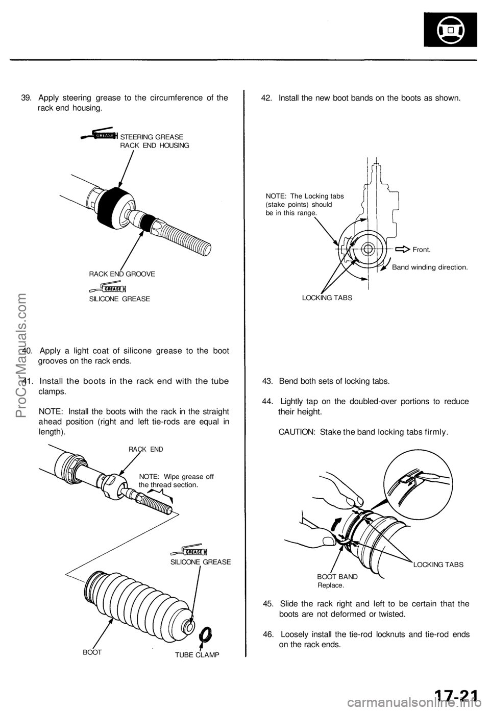
39. Appl y steerin g greas e t o th e circumferenc e o f th e
rac k en d housing .
STEERIN G GREAS E
RAC K EN D HOUSIN G
RAC K EN D GROOV E
40. Appl y a ligh t coa t o f silicon e greas e t o th e boo t
groove s o n th e rac k ends .
41. Instal l th e boot s i n th e rac k en d wit h th e tub e
clamps .
NOTE : Instal l th e boot s wit h th e rac k i n th e straigh t
ahea d positio n (righ t an d lef t tie-rod s ar e equa l i n
length) .
NOTE: Wip e greas e of fthe threa d section .
SILICON E GREAS E
BOO T
TUBE CLAM P
42. Instal l th e ne w boo t band s o n th e boot s a s shown .
NOTE: Th e Lockin g tab s
(stak e points ) shoul d
b e i n thi s range .
LOCKIN G TAB S
43. Ben d bot h set s o f lockin g tabs .
44 . Lightl y ta p o n th e doubled-ove r portion s t o reduc e
their height .
CAUTION : Stak e th e ban d lockin g tab s firmly .
LOCKIN G TAB S
BOO T BAN D
Replace .
45. Slid e th e rac k righ t an d lef t t o b e certai n tha t th e
boot s ar e no t deforme d o r twisted .
46 . Loosel y instal l th e tie-ro d locknut s an d tie-ro d end s
o n th e rac k ends .
SILICON E GREAS E
Band windin g direction .
Front.
RACK EN D
ProCarManuals.com
Page 486 of 1771
Steering Gearbox
Installation
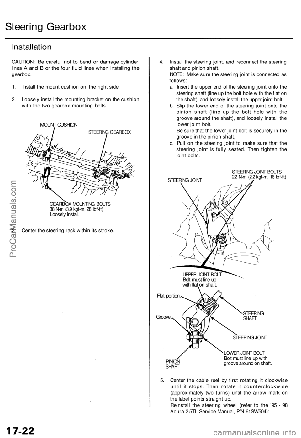
CAUTION: Be careful not to bend or damage cylinder
lines A and B or the four fluid lines when installing the
gearbox.
1. Install the mount cushion on the right side.
2. Loosely install the mounting bracket on the cushion
with the two gearbox mounting bolts.
MOUNT CUSHION
STEERING GEARBOX
GEARBOX MOUNTING BOLTS
38 N-m (3.9 kgf-m, 28 Ibf-ft)
Loosely install.
3. Center the steering rack within its stroke.
4. Install the steering joint, and reconnect the steering
shaft and pinion shaft.
NOTE: Make sure the steering joint is connected as
follows:
a. Insert the upper end of the steering joint onto the
steering shaft (line up the bolt hole with the flat on
the shaft), and loosely install the upper joint bolt,
b. Slip the lower end of the steering joint onto the
pinion shaft (line up the bolt hole with the
groove around the shaft), and loosely install the
lower joint bolt.
Be sure that the lower joint bolt is securely in the
groove in the pinion shaft,
c. Pull on the steering joint to make sure that the
steering joint is fully seated. Then tighten the
joint bolts.
STEERING JOINT
STEERING JOINT BOLTS
2.2 N-m (2.2 kgf-m, 16 Ibf-ft)
UPPER JOINT BOLT
Bolt must line up
with flat on shaft.
Flat portion.
Groove.
STEERING
SHAFT
PINION
SHAFT
STEERING JOINT
LOWER JOINT BOLT
Bolt must line up with
groove around on shaft.
5. Center the cable reel by first rotating it clockwise
until it stops. Then rotate it counterclockwise
(approximately two turns) until the arrow mark on
the label points straight up.
Reinstall the steering wheel (refer to the '95 - 98
Acura 2.5TL Service Manual, P/N 61SW504):ProCarManuals.com
Page 488 of 1771
Steering Gearbo x
Installatio n (cont'd )
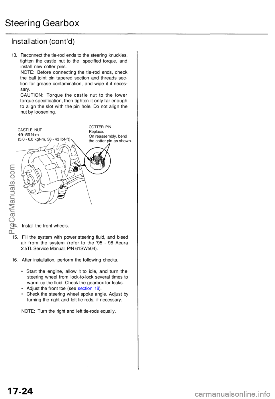
13. Reconnec t th e tie-ro d end s t o th e steerin g knuckles ,
tighte n th e castl e nu t t o th e specifie d torque , an d
instal l ne w cotte r pins .
NOTE : Befor e connectin g th e tie-ro d ends , chec k
th e bal l join t pi n tapere d sectio n an d thread s sec -
tio n fo r greas e contamination , an d wip e i t i f neces -
sary.
CAUTION : Torqu e th e castl e nu t t o th e lowe r
torqu e specification , the n tighte n it onl y fa r enoug h
t o alig n th e slo t wit h th e pi n hole . D o no t alig n th e
nu t b y loosening .
14 . Instal l th e fron t wheels .
15 . Fil l th e syste m wit h powe r steerin g fluid , an d blee d
ai r fro m th e syste m (refe r t o th e '9 5 - 9 8 Acur a
2.5T L Servic e Manual , P/ N 61SW504) .
16 . Afte r installation , perfor m th e followin g checks .
• Star t th e engine , allo w it t o idle , an d tur n th e
steerin g whee l fro m lock-to-loc k severa l time s t o
war m u p th e fluid . Chec k th e gearbo x fo r leaks .
• Adjus t th e fron t to e (se e sectio n 18 ).
• Chec k th e steerin g whee l spok e angle . Adjus t b y
turning the righ t an d lef t tie-rods , i f necessary .
NOTE : Tur n th e righ t an d lef t tie-rod s equally .
CASTLE NU T49 - 5 9 N- m(5. 0 - 6. 0 kgf-m , 3 6 - 4 3 Ibf-ft )
COTTE R PI NReplace .On reassembly , ben d
th e cotte r pi n a s shown .
ProCarManuals.com
Page 493 of 1771
Torque Specification s
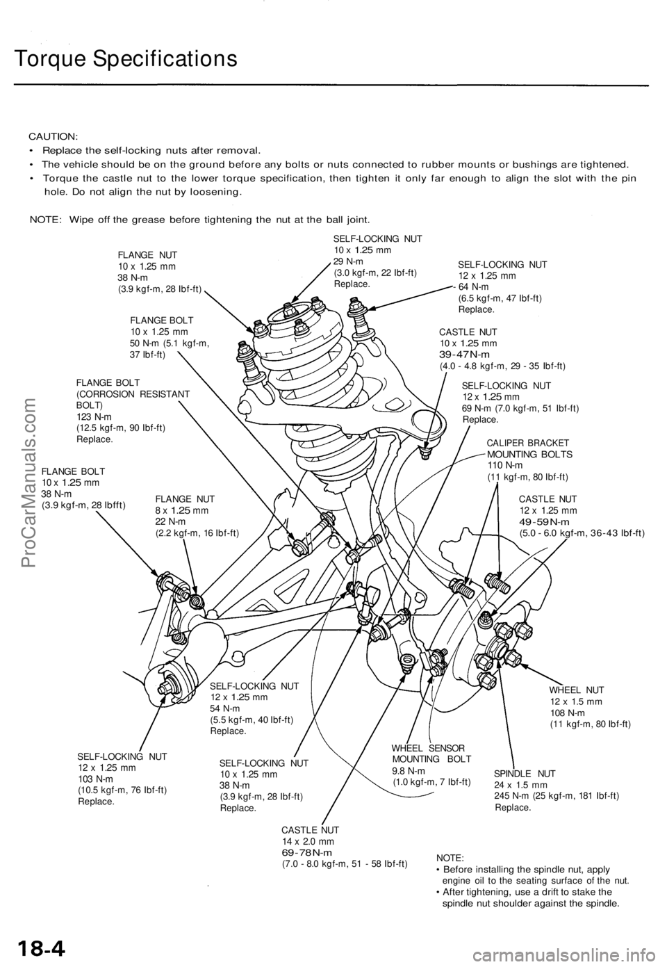
CAUTION:
• Replac e th e self-lockin g nut s afte r removal .
• Th e vehicl e shoul d b e o n th e groun d befor e an y bolt s o r nut s connecte d t o rubbe r mount s o r bushing s ar e tightened .
• Torqu e th e castl e nu t t o th e lowe r torqu e specification , the n tighte n i t onl y fa r enoug h t o alig n th e slo t wit h th e pi n
hole . D o no t alig n th e nu t b y loosening .
NOTE : Wip e of f th e greas e befor e tightenin g th e nu t a t th e bal l joint .
SELF-LOCKIN G NU T10 x 1.2 5 mm29 N- m(3.0 kgf-m , 2 2 Ibf-ft )Replace .
FLANGE BOL T10 x 1.2 5 mm38 N- m(3.9 kgf-m , 2 8 Ibfft )
SELF-LOCKIN G NU T12 x 1.2 5 mm
- 6 4 N- m
(6.5 kgf-m , 4 7 Ibf-ft )Replace .
CASTLE NU T10 x 1.2 5 mm39 - 4 7 N- m(4. 0 - 4. 8 kgf-m , 2 9 - 3 5 Ibf-ft )
SELF-LOCKIN G NU T
12 x 1.2 5 mm69 N- m (7. 0 kgf-m , 5 1 Ibf-ft )
Replace .
CALIPER BRACKE TMOUNTING BOLT S110 N- m(11 kgf-m , 8 0 Ibf-ft )
CASTL E NU T
12 x 1.2 5 mm49 - 5 9 N- m(5. 0 - 6. 0 kgf-m , 36-4 3 Ibf-ft )
SELF-LOCKIN G NU T12 x 1.2 5 mm103 N- m(10. 5 kgf-m , 7 6 Ibf-ft )Replace .
SELF-LOCKIN G NU T10 x 1.2 5 mm38 N- m(3.9 kgf-m , 2 8 Ibf-ft )Replace .
CASTLE NU T14 x 2. 0 m m69 - 7 8 N- m(7. 0 - 8. 0 kgf-m , 5 1 - 5 8 Ibf-ft ) WHEE
L NU T
12 x 1. 5 m m108 N- m(11 kgf-m , 8 0 Ibf-ft )
SPINDL E NU T
24 x 1. 5 m m245 N- m (2 5 kgf-m , 18 1 Ibf-ft )Replace .
NOTE:• Befor e installin g th e spindl e nut , appl yengin e oi l t o th e seatin g surfac e o f th e nut .• Afte r tightening , us e a drif t t o stak e th espindl e nu t shoulde r agains t th e spindle .
FLANGE NU T10 x 1.2 5 mm38 N- m(3.9 kgf-m , 2 8 Ibf-ft )
FLANG E BOL T
10 x 1.2 5 mm50 N- m (5. 1 kgf-m ,
3 7 Ibf-ft )
FLANG E NU T
8 x 1.2 5 mm22 N- m(2.2 kgf-m , 1 6 Ibf-ft )
FLANG
E BOL T
(CORROSIO N RESISTAN T
BOLT)123 N- m(12. 5 kgf-m , 9 0 Ibf-ft )Replace .
WHEEL SENSO R
MOUNTIN G BOL T
9.8 N- m(1.0 kgf-m , 7 Ibf-ft )
SELF-LOCKIN
G NU T
12 x 1.2 5 mm54 N- m(5.5 kgf-m , 4 0 Ibf-ft )Replace .
ProCarManuals.com
Page 496 of 1771
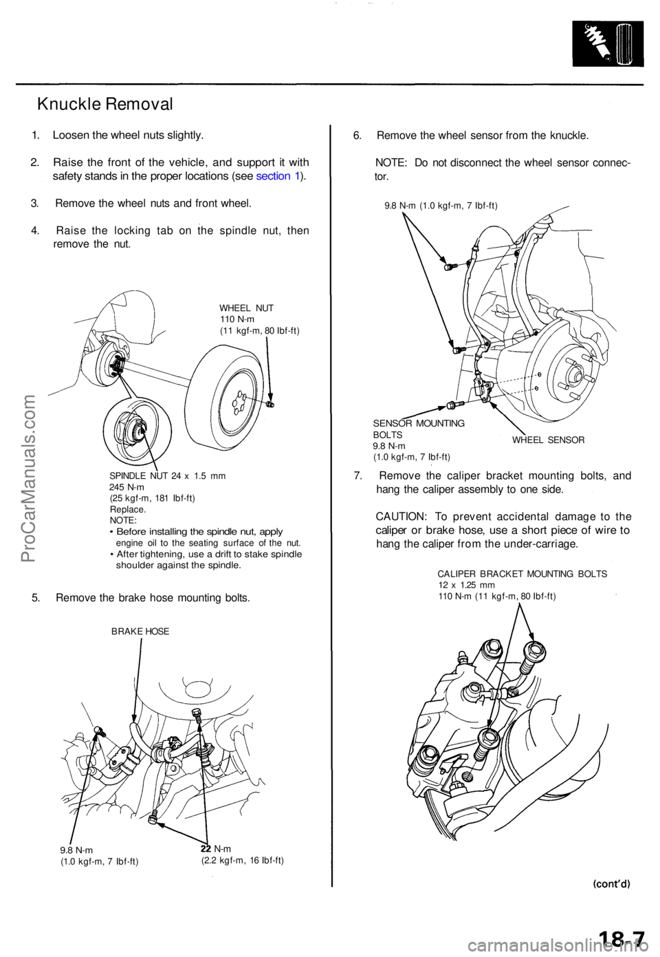
1. Loose n th e whee l nut s slightly .
2. Rais e th e fron t o f th e vehicle , an d suppor t i t wit h
safet y stand s in th e prope r location s (se e sectio n 1 ).
3 . Remov e th e whee l nut s an d fron t wheel .
4 . Rais e th e lockin g ta b o n th e spindl e nut , the n
remov e th e nut .
WHEE L NU T110 N- m(11 kgf-m , 8 0 Ibf-ft )
SPINDL E NU T 2 4 x 1. 5 m m
245 N- m(25 kgf-m , 18 1 Ibf-ft )
Replace .
NOTE :
• Befor e installin g th e spindl e nut , appl yengin e oi l t o th e seating surface o f th e nut .• Afte r tightening , us e a drif t t o stak e spindl eshoulde r agains t th e spindle .
5. Remov e th e brak e hos e mountin g bolts .
BRAK E HOS E
9.8 N- m(1.0 kgf-m , 7 Ibf-ft )
N-m(2. 2 kgf-m , 1 6 Ibf-ft )
6. Remov e th e whee l senso r fro m th e knuckle .
NOTE : D o no t disconnec t th e whee l senso r connec -
tor.
9.8 N- m (1. 0 kgf-m , 7 Ibf-ft )
SENSO R MOUNTIN GBOLTS9.8 N- m(1.0 kgf-m , 7 Ibf-ft ) WHEE
L SENSO R
7. Remov e th e calipe r bracke t mountin g bolts , an d
han g th e calipe r assembl y t o on e side .
CAUTION : T o preven t accidenta l damag e t o th e
calipe r o r brak e hose , us e a shor t piec e o f wir e t o
han g th e calipe r fro m th e under-carriage .
CALIPER BRACKE T MOUNTIN G BOLT S12 x 1.2 5 mm110 N- m (1 1 kgf-m , 8 0 Ibf-ft )
Knuckle Removal
ProCarManuals.com