Page 651 of 1771

Precautions/Procedures
Steering-related Precaution s
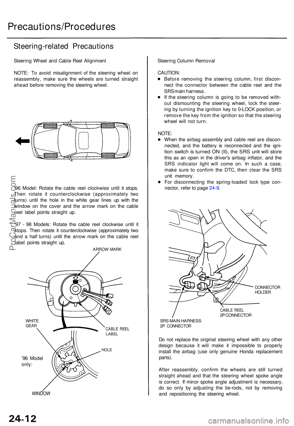
Steering Whee l an d Cabl e Ree l Alignmen t
NOTE : T o avoi d misalignmen t o f th e steerin g whee l o n
reassembly , mak e sur e th e wheel s ar e turne d straigh t
ahea d befor e removin g th e steerin g wheel .
'9 6 Model : Rotat e th e cabl e ree l clockwis e unti l i t stops .
The n rotat e i t counterclockwis e (approximatel y tw o
turns ) unti l th e hol e i n th e whit e gea r line s u p wit h th e
windo w o n th e cove r an d th e arro w mar k o n th e cabl e
ree l labe l point s straigh t up .
'9 7 - 9 8 Models : Rotat e th e cabl e ree l clockwis e unti l i t
stops . The n rotat e i t counterclockwis e (approximatel y tw o
an d a hal f turns ) unti l th e arro w mar k o n th e cabl e ree l
labe l point s straigh t up .
ARRO W MAR K
WHITEGEARCABL E REE LLABE L
HOLE
'96 Mode l
only:
WINDO W
Steering Colum n Remova l
CAUTION :
Before removin g th e steerin g column , firs t discon -
nec t th e connecto r betwee n th e cabl e ree l an d th e
SR S mai n harness .
I f th e steerin g colum n is goin g t o b e remove d with -
ou t dismountin g th e steerin g wheel , loc k th e steer -
in g b y turnin g th e ignitio n ke y t o 0-LOC K position , o r
remov e th e ke y fro m th e ignitio n s o tha t th e steerin g
whee l wil l no t turn .
NOTE :
Whe n th e airba g assembl y an d cabl e ree l ar e discon -
nected , an d th e batter y i s reconnecte d an d th e igni -
tion switc h is turne d O N (II) , th e SR S uni t wil l stor e
this a s a n ope n i n th e driver' s airba g inflator , an d th e
SR S indicato r ligh t wil l com e on . I n suc h a case ,
mak e sur e t o confir m th e DTC , the n clea r th e SR S
uni t memory .
Fo r disconnectin g th e spring-loade d loc k typ e con -
nector , refe r t o pag e 24-9 .
CONNECTO RHOLDER
CABLE REE L2P CONNECTO R
SRS MAI N HARNES S2P CONNECTO R
Do no t replac e th e origina l steerin g whee l wit h an y othe r
desig n becaus e i t will mak e i t impossibl e t o properl y
instal l th e airba g (us e onl y genuin e Hond a replacemen t
parts).
After reassembly , confir m th e wheel s ar e stil l turne d
straigh t ahea d an d tha t th e steerin g whee l spok e angl e
i s correct . I f mino r spok e angl e adjustmen t i s necessary ,
d o s o onl y b y adjustin g th e tie-rods , no t b y removin g
an d repositionin g th e steerin g wheel .
ProCarManuals.com
Page 666 of 1771

Cable Reel
Replacement (cont'd)
12.
NOTE:
Before installing the steering wheel, the front
wheels should be aligned straight ahead.
Be sure to install the harness wires so that they
are not pinched or interfering with other parts.
After reassembly, confirm that the wheels are
still turned straight ahead and that the steering
wheel spoke angle is correct (road test). If minor
spoke angle adjustment is necessary, do so only
by adjusting the tie-rods, not by removing and
repositioning the steering wheel.
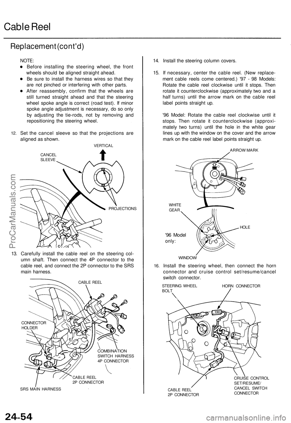
Set the cancel sleeve so that the projections are
aligned as shown.
VERTICAL
CANCEL
SLEEVE
PROJECTIONS
13. Carefully install the cable reel on the steering col-
umn shaft. Then connect the 4P connector to the
cable reel, and connect the 2P connector to the SRS
main harness.
CABLE REEL
CONNECTOR
HOLDER
COMBINATION
SWITCH HARNESS
4P CONNECTOR
CABLE REEL
2P CONNECTOR
SRS MAIN HARNESS
14. Install the steering column covers.
15. If necessary, center the cable reel. (New replace-
ment cable reels come centered.) '97 - 98 Models:
Rotate the cable reel clockwise until it stops. Then
rotate it counterclockwise (approximately two and a
half turns) until the arrow mark on the cable reel
label points straight up.
'96 Model: Rotate the cable reel clockwise until it
stops. Then rotate it counterclockwise (approxi-
mately two turns) until the hole in the white gear
lines up with the window on the cover and the arrow
mark on the cable reel label points straight up.
ARROW MARK
WHITE
GEAR
'96 Model
only:
HOLE
16.
WINDOW
Install the steering wheel, then connect the horn
connector and cruise control set/resume/cancel
switch connector.
STEERING WHEEL
BOLT
HORN CONNECTOR
CABLE REEL
2P CONNECTOR
CRUISE CONTROL
SET/RESUME/
CANCEL SWITCH
CONNECTORProCarManuals.com
Page 670 of 1771
EngineEngine Removal/Installation5±1 . . . . . . . . . . . . . . . . . . . . . . . .
Cylinder Head/Valve Train6±1 . . . . . . . . . . . . . . . . . . . . . . . . . . .
Engine Block7±1 . . . . . . . . . . . . . . . . . . . . . . . . . . . . . . . . . . . . . .
Engine Lubrication8±1 . . . . . . . . . . . . . . . . . . . . . . . . . . . . . . . . .
Intake Manifold/Exhaust System9±1 . . . . . . . . . . . . . . . . . . . .
Cooling10±1 . . . . . . . . . . . . . . . . . . . . . . . . . . . . . . . . . . . . . . . . . . . .
ProCarManuals.com
Page 686 of 1771
Lift and Support Points
Lift and Safety Stands
1. Place the lift blocks as shown.
2. Raise the hoist a few inches (centimeters), and rock the vehicle to be sure it is firmly supported.
3. Raise the hoist to full height, and inspect lift points for solid support.
NOTE: Use the same support points to support the vehicle on safety stands.
FRONT SUPPORT POINT
LIFT BLOCKS
REAR SUPPORT POINTProCarManuals.com
Page 687 of 1771
Floor Jack
1. Set the parking brake, and block the wheels that are
not being lifted.
2. When lifting the rear of the vehicle, put the shift
lever in position.
3. Raise the vehicle high enough to insert the safety
stands.
4. Adjust and place the safety stands so the vehicle
will be approximately level, then lower the vehicle
onto them.
• Always use safety stands when working on or under
any vehicle that is supported by only a jack.
• Never attempt to use a bumper jack for lifting or
supporting the vehicle.
Front
Center the jack
bracket in the middle
of the jack lift platform.
JACK LIFT PLATFORM
Rear
Center the jack
bracket in the middle
of the jack lift platform.
JACK LIFT PLATFORMProCarManuals.com
Page 705 of 1771
NOTE: Lubricate all hinges, latches, and locks once a year.
In corrosive areas, more frequent lubrication is necessary.
We recommend Honda White Lithium Grease.ProCarManuals.com
Page 720 of 1771
Engine Removal/Installation
Removal (cont'd)
7. Remove the battery cables from the under-hood fuse/
relay box.
BATTERY
CABLES
8.
9.
UNDER-HOOD
FUSE/RELAY BOX
Disconnect the engine wire harness connector on
the right (passenger's) side of the engine compart-
ment.
Remove the battery cable from the under-hood ABS
fuse/relay box.
BATTERY
CABLE
ENGINE WIRE
HARNESS
UNDER-HOOD ABS
FUSE/RELAY BOX
10. Remove the intake air duct and vacuum hose.
INTAKE AIR
DUCT
11.
VACUUM
HOSE
Remove the adjusting bolt, locknut and mounting
bolt, then remove the power steering (P/S) pump
belt and pump.
MOUNTING BOLT
10 x
1.25
mm
49 N-m (5.0 kgf-m, 36 Ibf-ft)
ADJUSTING
BOLT
P/S PUMP
BELT
LOCKNUT
8 x
1.25
mm
22 N-m (2.2 kgf-m,
16 Ibf-ft)ProCarManuals.com
Page 721 of 1771

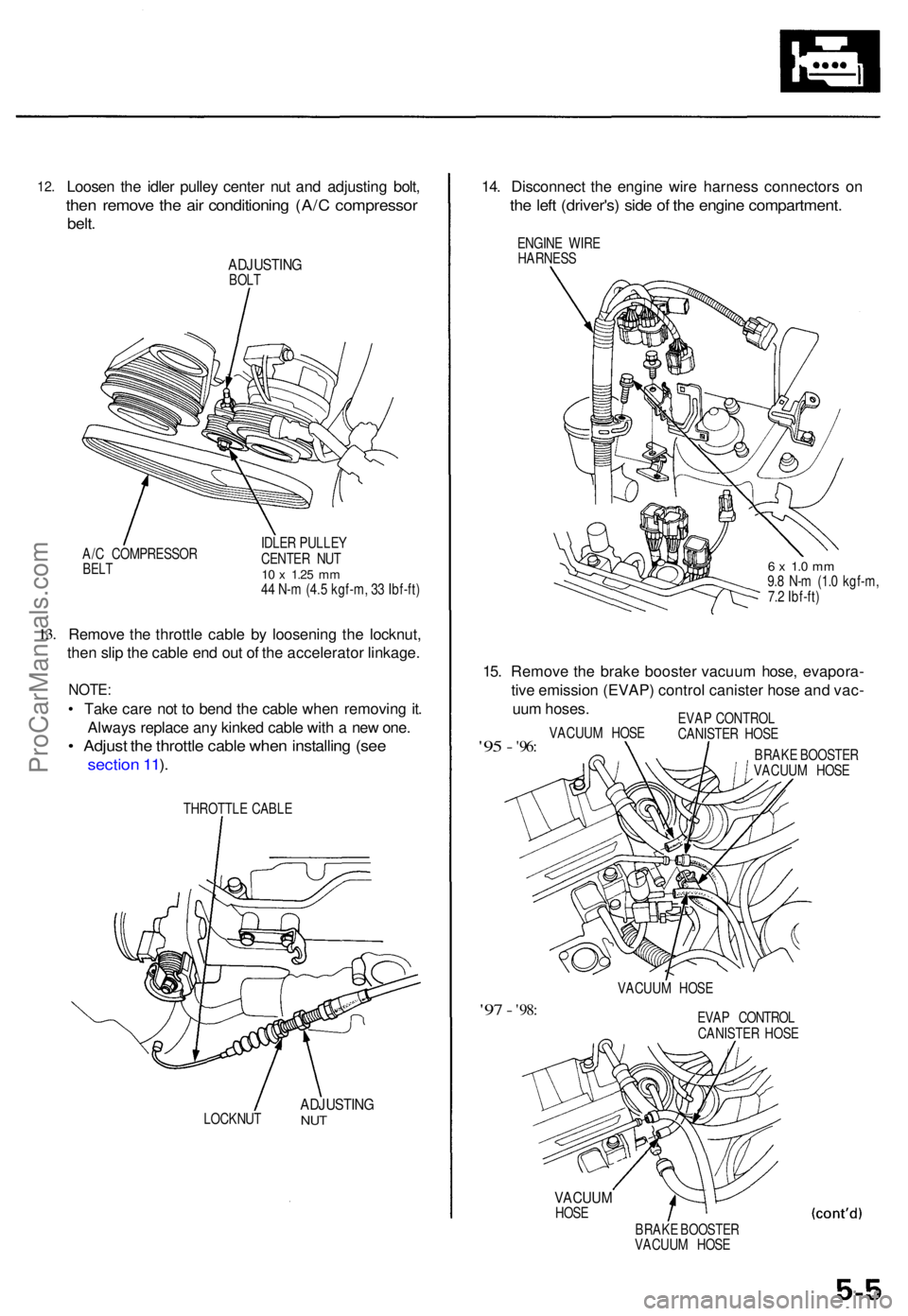
12.Loose n th e idle r pulle y cente r nu t an d adjustin g bolt ,
then remov e th e ai r conditionin g (A/ C compresso r
belt.
ADJUSTIN GBOLT
A/ C COMPRESSO R
BELT
IDLE R PULLE Y
CENTE R NU T
10 x 1.2 5 mm44 N- m (4.5 kgf-m , 3 3 Ibf-ft )
13.Remov e th e throttl e cabl e b y loosenin g th e locknut ,
the n sli p th e cabl e en d ou t o f th e accelerato r linkage .
NOTE:
• Tak e car e no t t o ben d th e cabl e whe n removin g it .
Alway s replac e an y kinke d cabl e wit h a ne w one .
• Adjus t th e throttl e cabl e whe n installin g (se e
sectio n 11 ).
THROTTL E CABL E
LOCKNU T
ADJUSTIN GNUT
14. Disconnec t th e engin e wir e harnes s connector s o n
the lef t (driver's ) sid e o f th e engin e compartment .
ENGINE WIR E
HARNES S
6 x 1. 0 m m9.8 N- m (1. 0 kgf-m ,
7. 2 Ibf-ft )
15. Remov e th e brak e booste r vacuu m hose , evapora -
tiv e emissio n (EVAP ) contro l caniste r hos e an d vac -
uu m hoses .
'95 - '96 :VACUU M HOS E EVA
P CONTRO L
CANISTE R HOS E
BRAK E BOOSTE R
VACUU M HOS E
VACUU M HOS E
'97 - '98 :EVA P CONTRO L
CANISTE R HOS E
VACUU MHOSE
BRAKE BOOSTE R
VACUU M HOS E
ProCarManuals.com