1995 ACURA TL lock
[x] Cancel search: lockPage 808 of 1771
Oil Filter
Replacement
Be careful when loosening the oil filter
while the engine is hot. Burns can result because the oil
temperature is very high.
1. Remove the oil filter with the special oil filter wrench.
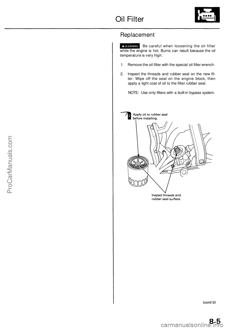
2. Inspect the threads and rubber seal on the new fil-
ter. Wipe off the seat on the engine block, then
apply a light coat of oil to the filter rubber seal.
NOTE: Use only filters with a built-in bypass system.ProCarManuals.com
Page 809 of 1771
Oil Filte r
Replacemen t (cont'd )
3. Instal l th e oi l filte r b y hand .
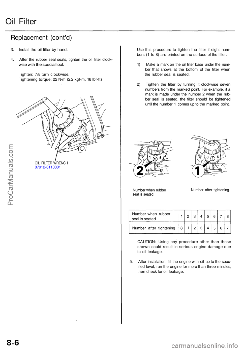
4. Afte r th e rubbe r sea l seats , tighte n th e oi l filte r clock -
wise wit h th e specia l tool .
Tighten : 7/ 8 tur n clockwise .
Tightenin g torque : 2 2 N- m (2. 2 kgf-m , 1 6 Ibf-ft )
OIL FILTE R WRENC H07912-611000 1
Use thi s procedur e t o tighte n th e filte r i f eigh t num -
ber s ( 1 t o 8 ) ar e printe d o n th e surfac e o f th e filter .
1 ) Mak e a mar k o n th e oi l filte r bas e unde r th e num -
be r tha t show s a t th e botto m o f th e filte r whe n
th e rubber seal i s seated .
2 ) Tighte n th e filte r b y turnin g i t clockwis e seve n
number s fro m th e marke d point . Fo r example , i f a
mar k i s mad e unde r th e numbe r 2 whe n th e rub -
be r sea l i s seated , th e filte r shoul d b e tightene d
unti l th e numbe r 1 come s u p to th e marke d point .
Numbe r whe n rubbe rseal i s seated .Number afte r tightening .
Number whe n rubbe r
sea l i s seate d
Numbe r afte r tightenin g1
8
2
1
3
2
4
3
5
4
6
5
7
6
8
7
CAUTION : Usin g an y procedur e othe r tha n thos e
show n coul d resul t i n seriou s engin e damag e du e
t o oi l leakage .
5 . Afte r installation , fil l th e engin e wit h oi l u p to th e spec -
ifie d level , ru n th e engin e fo r mor e tha n thre e minutes ,
the n chec k fo r oi l leakage .
ProCarManuals.com
Page 813 of 1771
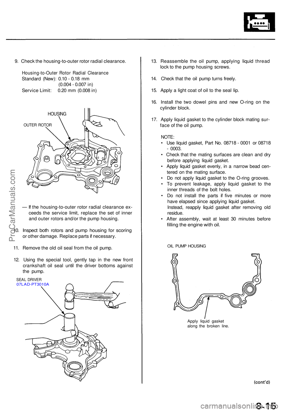
9. Chec k th e housing-to-oute r roto r radia l clearance .
Housing-to-Oute r Roto r Radia l Clearanc e
Standard (New) : 0.1 0 - 0.1 8 m m
(0.00 4 - 0.00 7 in )
Servic e Limit : 0.2 0 m m (0.00 8 in )
HOUSIN G
OUTER ROTO R
— If th e housing-to-oute r roto r radia l clearanc e ex -
ceed s th e servic e limit , replac e th e se t o f inne r
an d oute r rotor s and/o r th e pum p housing .
10. Inspec t bot h rotor s an d pum p housin g fo r scorin g
or othe r damage . Replac e part s if necessary .
11 . Remov e th e ol d oi l sea l fro m th e oi l pump .
12 . Usin g th e specia l tool , gentl y ta p i n th e ne w fron t
crankshaf t oi l sea l unti l th e drive r bottom s agains t
th e pump .
SEAL DRIVE R07LAD-PT3010 A
13. Reassembl e th e oi l pump , applyin g liqui d threa d
loc k t o th e pum p housin g screws .
14 . Chec k tha t th e oi l pum p turn s freely .
15 . Appl y a ligh t coa t o f oi l t o th e sea l lip .
16 . Instal l th e tw o dowe l pin s an d ne w O-rin g o n th e
cylinde r block .
17 . Appl y liqui d gaske t t o th e cylinde r bloc k matin g sur -
fac e o f th e oi l pump .
NOTE:
• Us e liqui d gasket , Par t No . 0871 8 - 000 1 o r 0871 8
- 0003 .
• Chec k tha t th e matin g surfaces are clea n an d dr y
befor e applyin g liqui d gasket .
• Appl y liqui d gaske t evenly , i n a narro w bea d cen -
tere d o n th e matin g surface .
• D o no t appl y liqui d gaske t t o th e O-rin g grooves .
• T o preven t leakage , appl y liqui d gaske t t o th e
inne r thread s o f th e bol t holes .
• D o no t instal l th e part s i f fiv e minute s o r mor e
hav e elapse d sinc e applyin g liqui d gasket .
Instead , reappl y liqui d gaske t afte r removin g ol d
residue .
• Afte r assembly , wai t a t leas t 3 0 minute s befor e
filling th e engin e wit h oil .
OIL PUM P HOUSIN G
Apply liqui d gaske t
alon g th e broke n line .
ProCarManuals.com
Page 814 of 1771
Removal/lnspection/lnstallation
(cont'd)
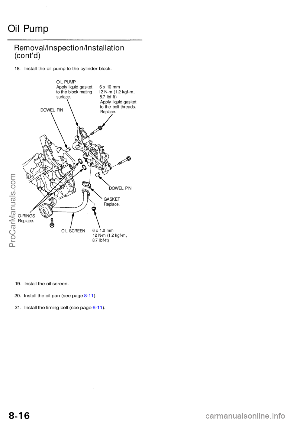
18. Instal l th e oi l pum p to th e cylinde r block .
OIL PUM P
Appl y liqui d gaske t 6 x 10 m m
t o th e bloc k matin g 1 2 N- m (1. 2 kgf-m ,
surface . 8. 7 Ibf-ft )Apply liqui d gaske t
t o th e bol t threads .
Replace .DOWEL PI N
O-RING SReplace .
OIL SCREE N6 x 1. 0 m m12 N- m (1. 2 kgf-m ,8.7 Ibf-ft )
19. Instal l th e oi l screen .
20 . Instal l th e oi l pa n (se e pag e 8-11 ).
21 . Instal l th e timin g bel t (se e pag e 6-11 ).
DOWE L PI N
GASKE TReplace .
Oil Pum p
ProCarManuals.com
Page 817 of 1771
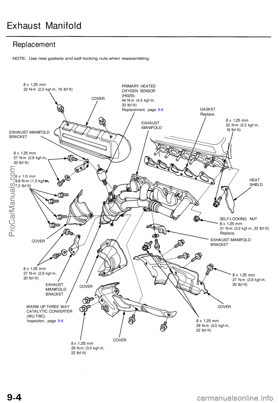
Exhaust Manifol d
Replacemen t
NOTE: Us e ne w gasket s an d self-lockin g nut s whe n reassembling .
8 x 1.2 5 mm22 N- m (2. 2 kgf-m , 1 6 Ibf-ft )
COVER PRIMAR
Y HEATE D
OXYGE N SENSO R
(H02S)44 N- m (4. 5 kgf-m ,
3 3 Ibf-ft )
Replacement , pag e 9- 6 GASKE
T
Replace .
EXHAUS T MANIFOL DBRACKET
8 x 1.2 5 mm27 N- m (2. 8 kgf- m
2 0 Ibf-ft )
6 x 1. 0 m m9.8 N- m (1. 0 kg f7.2 Ibf-ft )
8 x 1.2 5 mm22 N- m (2. 2 kgf-m ,
1 6 Ibf-ft )
HEAT
SHIEL D
SELF-LOCKIN G NU T
8 x 1.2 5 m m31 N- m (3. 2 kgf-m , 2 3 Ibf-ft )Replace .
8 x 1.2 5 mm27 N- m (2. 8 kgf-m ,
2 0 Ibf-ft )
EXHAUS T
MANIFOL DBRACKET
WARM U P THRE E WA Y
CATALYTI C CONVERTE R
(WU-TWC )
Inspection , pag e 9- 6
8 x 1.2 5 mm27 N- m (2. 8 kgf-m ,
2 0 Ibf-ft )
COVE R
8 x 1.2 5 mm29 N- m (3. 0 kgf-m ,
2 2 Ibf-ft )
8 x 1.2 5 mm29 N- m (3. 0 kgf-m ,
2 2 Ibf-ft )
COVE R
EXHAUS TMANIFOL D
EXHAUST MANIFOL DBRACKETCOVER
COVER
ProCarManuals.com
Page 818 of 1771
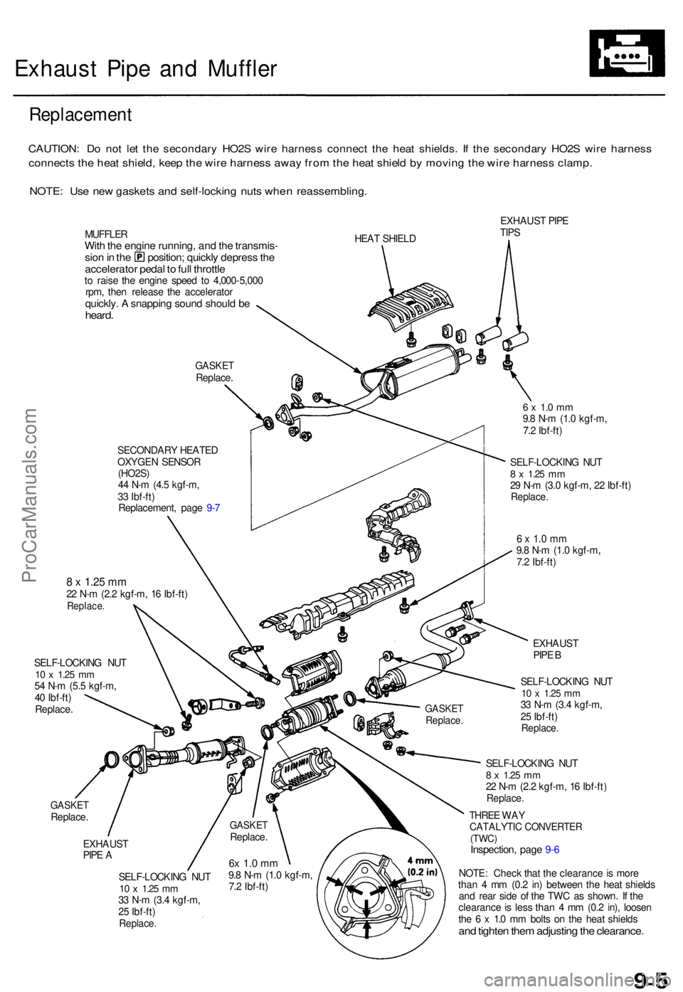
Exhaust Pip e an d Muffle r
Replacemen t
CAUTION: D o no t le t th e secondar y HO2 S wir e harnes s connec t th e hea t shields . I f th e secondar y HO2 S wir e harnes s
connect s th e hea t shield , kee p th e wir e harnes s awa y fro m th e hea t shiel d b y movin g th e wir e harnes s clamp .
NOTE: Us e ne w gasket s an d self-lockin g nut s whe n reassembling .
MUFFLERWith th e engin e running , an d th e transmis -sion in th e position ; quickl y depres s th eaccelerato r peda l t o ful l throttl eto rais e th e engin e spee d t o 4,00 0-5,00 0
rpm , the n releas e th e accelerato r
quickly. A snappin g soun d shoul d b eheard .
GASKE TReplace .
SECONDAR Y HEATE D
OXYGE N SENSO R
(HO2S )
4 4 N- m (4. 5 kgf-m ,
3 3 Ibf-ft )
Replacement , pag e 9- 7 HEA
T SHIEL D EXHAUS
T PIP E
TIP S
GASKE TReplace .
8 x 1.2 5 mm22 N- m (2. 2 kgf-m , 1 6 Ibf-ft )Replace .
SELF-LOCKIN G NU T10 x 1.2 5 mm54 N- m (5. 5 kgf-m ,
4 0 Ibf-ft )
Replace .
6 x 1. 0 m m9.8 N- m (1. 0 kgf-m ,
7. 2 Ibf-ft )
SELF-LOCKIN G NU T
8 x 1.2 5 mm29 N- m (3. 0 kgf-m , 2 2 Ibf-ft )Replace .
6 x 1. 0 m m9.8 N- m (1. 0 kgf-m ,
7. 2 Ibf-ft )
EXHAUS T
PIP E A
SELF-LOCKIN G NU T
10 x 1.2 5 mm33 N- m (3. 4 kgf-m ,
2 5 Ibf-ft )
Replace .
EXHAUS T
PIP E B
SELF-LOCKIN G NU T
10 x 1.2 5 mm33 N- m (3. 4 kgf-m ,
2 5 Ibf-ft )
Replace .
SELF-LOCKIN G NU T8 x 1.2 5 mm22 N- m (2. 2 kgf-m , 1 6 Ibf-ft )Replace .
THREE WA YCATALYTI C CONVERTE R(TWC)Inspection , pag e 9- 6
NOTE : Chec k tha t th e clearanc e is mor e
tha n 4 m m (0. 2 in ) betwee n th e hea t shield s
an d rea r sid e o f th e TW C a s shown . I f th e
clearanc e is les s tha n 4 m m (0. 2 in) , loose n
th e 6 x 1. 0 m m bolt s o n th e hea t shield s
and tighte n the m adjustin g th e clearance .
6x 1. 0 m m9.8 N- m (1. 0 kgf-m ,
7. 2 Ibf-ft )
GASKE TReplace .
GASKETReplace .
ProCarManuals.com
Page 822 of 1771
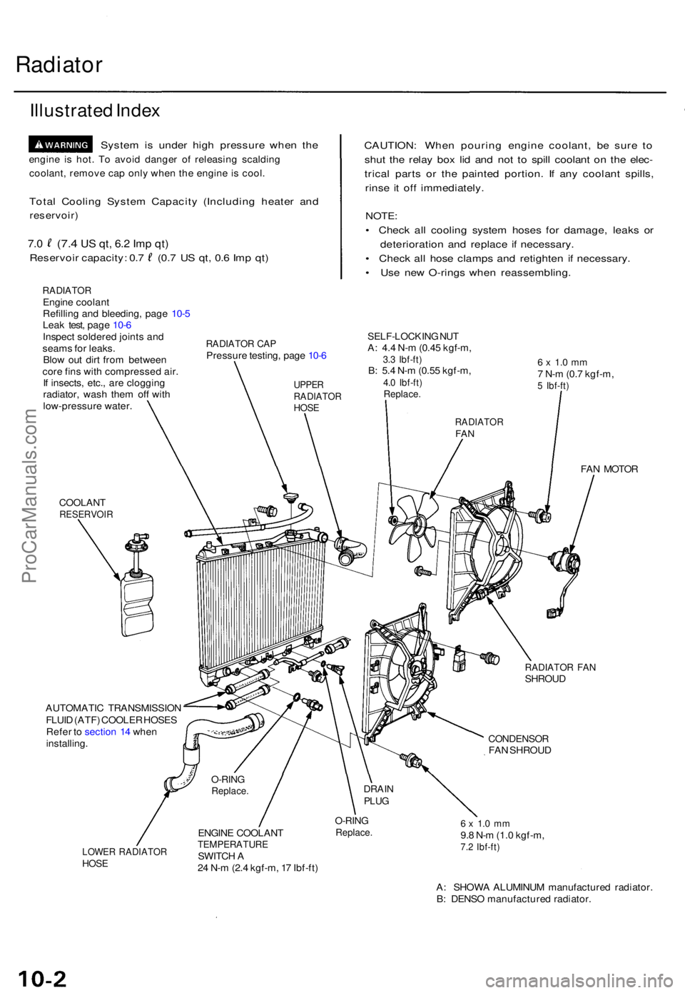
Radiator
Illustrate d Inde x
Syste m is unde r hig h pressur e whe n th e
engin e i s hot . T o avoi d dange r o f releasin g scaldin g
coolant , remov e ca p onl y whe n th e engin e i s cool .
Total Coolin g Syste m Capacit y (Includin g heate r an d
reservoir )
7.0 (7. 4 US qt , 6. 2 Im p qt )
Reservoi r capacity : 0. 7 (0. 7 U S qt , 0. 6 Im p qt )
RADIATO REngine coolan t
Refillin g an d bleeding , pag e 10- 5
Lea k test , pag e 10- 6
Inspec t soldere d joint s an d
seam s fo r leaks .
Blo w ou t dir t fro m betwee n
cor e fin s wit h compresse d air .
I f insects , etc. , ar e cloggin g
radiator , was h the m of f wit h
low-pressur e water .
CAUTION : Whe n pourin g engin e coolant , b e sur e t o
shu t th e rela y bo x li d an d no t t o spil l coolan t o n th e elec -
trica l part s o r th e painte d portion . I f an y coolan t spills ,
rins e i t of f immediately .
NOTE:
• Chec k al l coolin g syste m hose s fo r damage , leak s o r
deterioratio n an d replac e i f necessary .
• Chec k al l hos e clamp s an d retighte n i f necessary .
• Us e ne w O-ring s whe n reassembling .
RADIATOR CA PPressur e testing , pag e 10- 6
SELF-LOCKIN G NU TA: 4. 4 N- m (0.4 5 kgf-m ,3.3 Ibf-ft )B: 5. 4 N- m (0.5 5 kgf-m ,4.0 Ibf-ft )Replace .
6 x 1. 0 m m7 N- m (0. 7 kgf-m ,5 Ibf-ft )
COOLAN TRESERVOI R
FAN MOTO R
RADIATO R FA NSHROU D
AUTOMATI C TRANSMISSIO N
FLUI D (ATF ) COOLE R HOSE S
Refe r t o sectio n 1 4 whe n
installing .
CONDENSO RFAN SHROU D
LOWER RADIATO RHOSE
ENGIN E COOLAN TTEMPERATUR ESWITCH A
2 4 N- m (2. 4 kgf-m , 1 7 Ibf-ft )
O-RIN GReplace .6 x 1. 0 m m9.8 N- m (1. 0 kgf-m ,7.2 Ibf-ft )
A: SHOW A ALUMINU M manufacture d radiator .
B : DENS O manufacture d radiator .
O-RINGReplace .DRAINPLUG
UPPE RRADIATO RHOSE
RADIATO RFAN
ProCarManuals.com
Page 825 of 1771
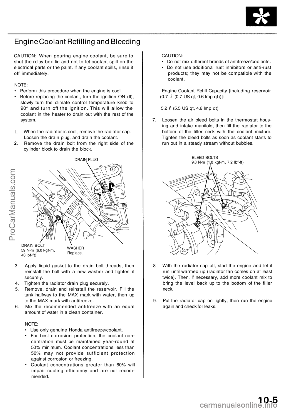
Engine Coolan t Refillin g an d Bleedin g
CAUTION : Whe n pourin g engin e coolant , b e sur e t o
shu t th e rela y bo x li d an d no t t o le t coolan t spil l o n th e
electrica l part s o r th e paint . I f an y coolan t spills , rins e it
of f immediately .
NOTE:
• Perfor m thi s procedur e whe n th e engin e i s cool .
• Befor e replacin g th e coolant , tur n th e ignitio n O N (II) ,
slowl y tur n th e climat e contro l temperatur e kno b t o
90 ° an d tur n of f th e ignition . Thi s wil l allo w th e
coolan t i n th e heate r t o drai n ou t wit h th e res t o f th e
system .
1.Whe n th e radiato r i s cool , remov e th e radiato r cap .
Loose n th e drai n plug , an d drai n th e coolant .
Remov e th e drai n bol t fro m th e righ t sid e o f th e
cylinde r bloc k t o drai n th e block .
DRAIN PLU G
DRAI N BOL T59 N- m (6. 0 kgf-m ,
4 3 Ibf-ft )WASHE RReplace.
3. Appl y liqui d gaske t t o th e drai n bol t threads , the n
reinstal l th e bol t wit h a ne w washe r an d tighte n i t
securely .
4. Tighte n th e radiato r drai n plu g securely .
5 . Remove , drai n an d reinstal l th e reservoir . Fil l th e
tan k halfwa y t o th e MA X mar k wit h water , the n u p
t o th e MA X mar k wit h antifreeze .
6 . Mi x th e recommende d antifreez e wit h a n equa l
amoun t o f wate r i n a clea n container .
NOTE:
• Us e onl y genuin e Hond a antifreeze/coolant .
• Fo r bes t corrosio n protection , th e coolan t con -
centratio n mus t b e maintaine d year-roun d a t
50 % minimum . Coolan t concentration s les s tha n
50 % ma y no t provid e sufficien t protectio n
agains t corrosio n o r freezing .
• Coolan t concentration s greate r tha n 60 % wil l
impai r coolin g efficienc y an d ar e no t recom -
mended .
7.
8.
9 .
CAUTION :
• D o no t mi x differen t brand s o f antifreeze/coolants .
• D o no t us e additiona l rus t inhibitor s o r anti-rus t
products ; the y ma y no t b e compatibl e wit h th e
coolant.
Engin e Coolan t Refil l Capacit y [includin g reservoi r
(0.7 (0. 7 U S qt , 0. 6 Im p qt))] :
5.2 (5. 5 US qt , 4. 6 Im p qt )
Loose n th e ai r blee d bolt s i n th e thermosta t hous -
in g an d intak e manifold , the n fil l th e radiato r t o th e
botto m o f th e fille r nec k wit h th e coolan t mixture .
Tighte n th e blee d bolt s a s soo n a s coolan t start s t o
ru n ou t i n a stead y strea m withou t bubbles .
BLEED BOLT S9.8 N- m (1. 0 kgf-m , 7. 2 Ibf-ft )
With th e radiato r ca p off , star t th e engin e an d le t i t
ru n unti l warme d u p (radiato r fa n come s o n a t leas t
twice) . Then , i f necessary , ad d mor e coolan t mi x t o
brin g th e leve l bac k u p t o th e botto m o f th e fille r
neck.
Put th e radiato r ca p o n tightly , the n ru n th e engin e
agai n an d chec k fo r leaks .
ProCarManuals.com