1995 ACURA TL lock
[x] Cancel search: lockPage 980 of 1771
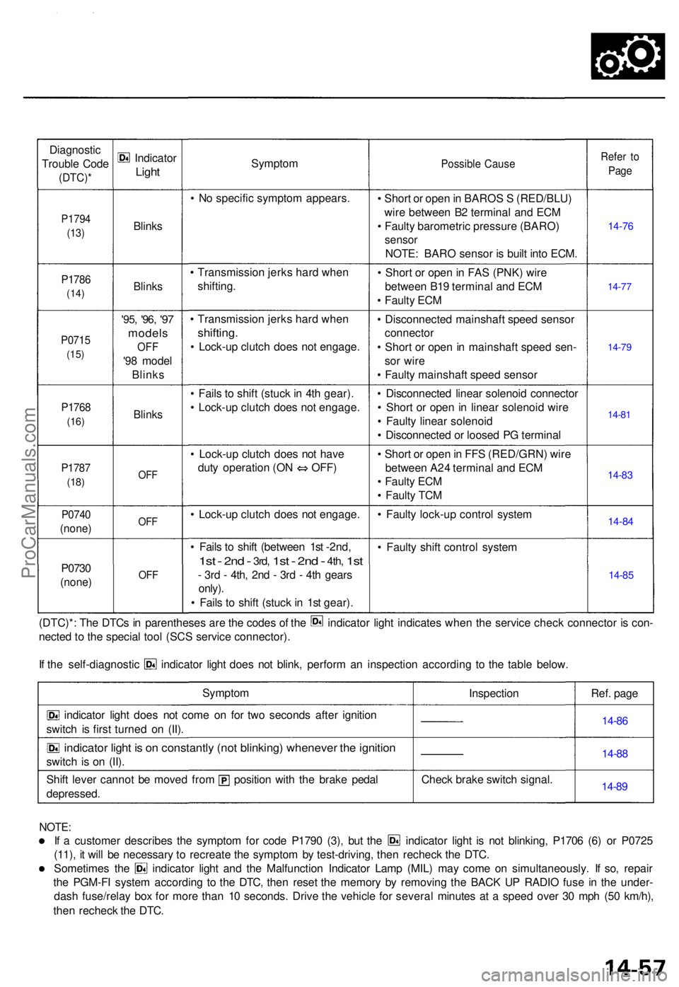
Diagnostic
Troubl e Cod e
(DTC) *
P1794
(13)
P178 6
(14)
P071 5
(15)
P176 8
(16)
P178 7
(18)
P074 0
(none )
P0730
(none )
Indicato r
Light
Blink s
Blinks
'95, '96 , '97
model s
OFF
'98 mode l
Blink s
Blinks
OFF
OF F
OFF
Sympto m
• N o specifi c sympto m appears .
• Transmissio n jerk s har d whe n
shifting .
• Transmissio n jerk s har d whe n
shifting .
• Lock-u p clutc h doe s no t engage .
• Fail s t o shif t (stuc k in 4t h gear) .
• Lock-u p clutc h doe s no t engage .
• Lock-u p clutc h doe s no t hav e
duty operatio n (O N OFF )
• Lock-u p clutc h doe s no t engage .
• Fail s t o shif t (betwee n 1s t -2nd,
1s t - 2n d - 3rd , 1st - 2nd - 4th , 1st
- 3r d - 4th , 2n d - 3r d - 4t h gear s
only) .
• Fail s t o shif t (stuc k in 1s t gear) .
Possibl e Caus e
• Shor t o r ope n in BARO S S (RED/BLU )
wir e betwee n B 2 termina l an d EC M
• Fault y barometri c pressur e (BARO )
sensor
NOTE : BAR O senso r i s buil t int o ECM .
• Shor t o r ope n in FA S (PNK ) wir e
betwee n B1 9 termina l an d EC M
• Fault y EC M
• Disconnecte d mainshaf t spee d senso r
connecto r
• Shor t o r ope n in mainshaf t spee d sen -
so r wir e
• Fault y mainshaf t spee d senso r
• Disconnecte d linea r solenoi d connecto r
• Shor t o r ope n in linea r solenoi d wir e
• Fault y linea r solenoi d
• Disconnecte d o r loose d P G termina l
• Shor t o r ope n in FF S (RED/GRN ) wir e
betwee n A2 4 termina l an d EC M
• Fault y EC M
• Fault y TC M
• Fault y lock-u p contro l syste m
• Fault y shif t contro l syste m
Refer t o
Pag e
14-7 6
14-77
14-7 9
14-8 1
14-8 3
14-8 4
14-8 5
(DTC)* : Th e DTC s i n parenthese s ar e th e code s o f th e indicato r ligh t indicate s whe n th e servic e chec k connecto r i s con -
necte d t o th e specia l too l (SC S servic e connector) .
If th e self-diagnosti c indicato r ligh t doe s no t blink , perfor m a n inspectio n accordin g t o th e tabl e below .
Sympto m
indicator ligh t doe s no t com e o n fo r tw o second s afte r ignitio n
switc h i s firs t turne d o n (II) .
indicato r ligh t i s o n constantl y (no t blinking ) wheneve r th e ignitio n
switch i s o n (II) .
Shif t leve r canno t b e move d fro m positio n wit h th e brak e peda l
depressed . Inspectio
n
Chec k brak e switc h signal . Ref
. pag e
14-86
14-8 8
14-8 9
NOTE :
If a custome r describe s th e sympto m fo r cod e P179 0 (3) , bu t th e indicato r ligh t i s no t blinking , P170 6 (6 ) o r P072 5
(11) , i t wil l b e necessar y t o recreat e th e sympto m b y test-driving , the n rechec k th e DTC .
Sometime s th e indicato r ligh t an d th e Malfunctio n Indicato r Lam p (MIL ) ma y com e o n simultaneously . I f so , repai r
th e PGM-F I syste m accordin g t o th e DTC , the n rese t th e memor y b y removin g th e BAC K U P RADI O fus e i n th e under -
das h fuse/rela y bo x fo r mor e tha n 1 0 seconds . Driv e th e vehicl e fo r severa l minute s a t a spee d ove r 3 0 mp h (5 0 km/h) ,
the n rechec k th e DTC .
ProCarManuals.com
Page 981 of 1771
Lock-up Contro l Solenoi d Valv e A/ B
Tes t
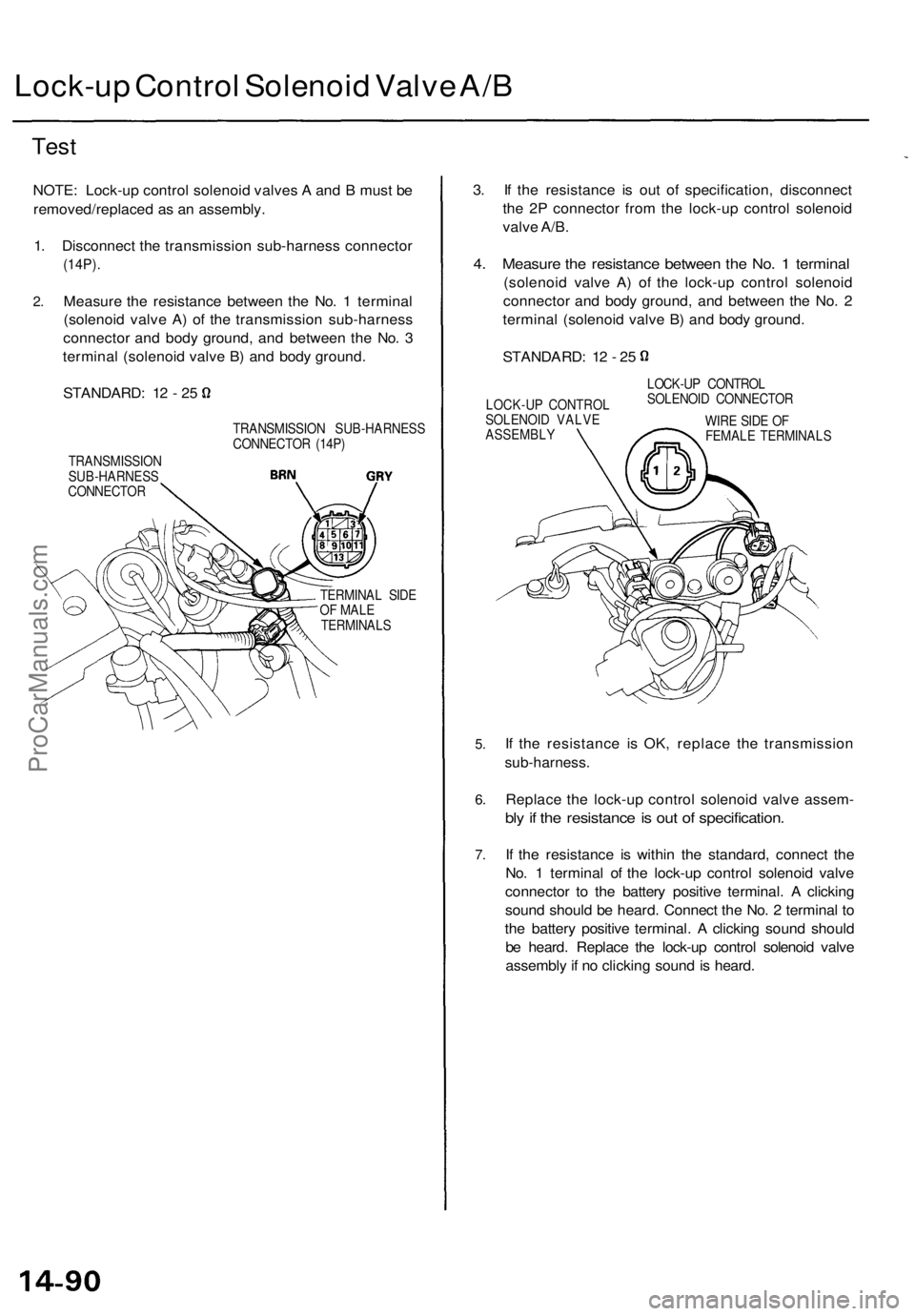
NOTE : Lock-u p contro l solenoi d valve s A an d B mus t b e
removed/replace d a s a n assembly .
1 . Disconnec t th e transmissio n sub-harnes s connecto r
(14P).
2.Measur e th e resistanc e betwee n th e No . 1 termina l
(solenoi d valv e A ) o f th e transmissio n sub-harnes s
connecto r an d bod y ground , an d betwee n th e No . 3
termina l (solenoi d valv e B ) an d bod y ground .
STANDARD : 1 2 - 2 5
TRANSMISSIO N
SUB-HARNES S
CONNECTO R TRANSMISSIO
N SUB-HARNES S
CONNECTO R (14P )
TERMINA L SID E
O F MAL E
TERMINAL S
3. I f th e resistanc e i s ou t of specification , disconnec t
th e 2 P connecto r fro m th e lock-u p contro l solenoi d
valv e A/B .
4. Measur e th e resistanc e betwee n th e No . 1 termina l
(solenoi d valv e A ) of the lock-u p contro l solenoi d
connecto r an d bod y ground , an d betwee n th e No . 2
termina l (solenoi d valv e B ) an d bod y ground .
STANDARD : 1 2 - 2 5
LOCK-U P CONTRO L
SOLENOI D VALV E
ASSEMBL Y LOCK-U
P CONTRO L
SOLENOI D CONNECTO R
WIR E SID E O F
FEMAL E TERMINAL S
5.
6.
7 .
If th e resistanc e i s OK , replac e th e transmissio n
sub-harness.
Replace th e lock-u p contro l solenoi d valv e assem -
bly if th e resistanc e is ou t o f specification .
If th e resistanc e i s withi n th e standard , connec t th e
No . 1 termina l o f th e lock-u p contro l solenoi d valv e
connecto r t o th e batter y positiv e terminal . A clickin g
soun d shoul d b e heard . Connec t th e No . 2 termina l t o
th e batter y positiv e terminal . A clickin g soun d shoul d
b e heard . Replac e th e lock-u p contro l solenoi d valv e
assembl y if n o clickin g soun d is heard .
ProCarManuals.com
Page 982 of 1771
Replacement
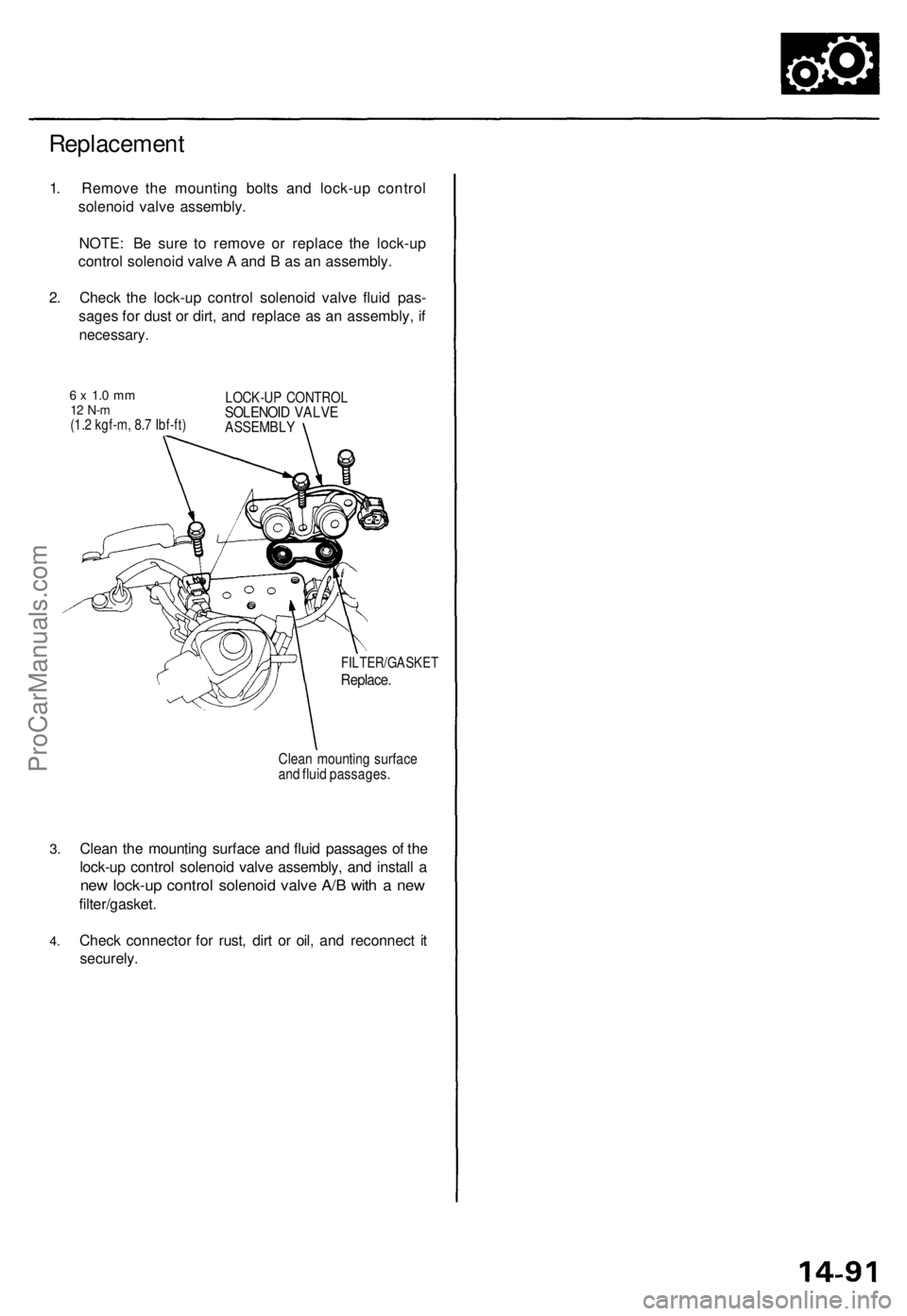
1. Remov e th e mountin g bolt s an d lock-u p contro l
solenoi d valv e assembly .
NOTE : B e sur e t o remov e o r replac e th e lock-u p
contro l solenoi d valv e A an d B as a n assembly .
2 . Chec k th e lock-u p contro l solenoi d valv e flui d pas -
sage s fo r dus t o r dirt , an d replac e a s a n assembly , i f
necessary .
6 x 1. 0 m m12 N- m(1.2 kgf-m , 8. 7 Ibf-ft )
LOCK-U P CONTRO LSOLENOID VALV EASSEMBL Y
3.
4 .
FILTER/GASKE T
Replace.
Clean mountin g surfac eand flui d passages .
Clean th e mountin g surfac e an d flui d passage s o f th e
lock-u p contro l solenoi d valv e assembly , an d instal l a
ne w lock-u p contro l solenoi d valv e A/ B wit h a ne w
filter/gasket .
Chec k connecto r fo r rust , dir t o r oil , an d reconnec t i t
securely .
ProCarManuals.com
Page 984 of 1771
Linear Solenoi d
Test
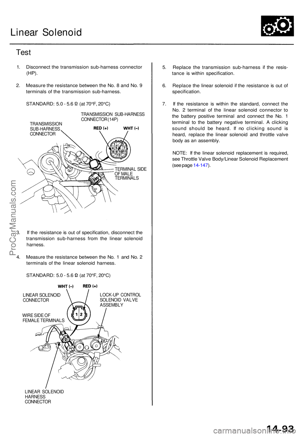
1. Disconnec t th e transmissio n sub-harnes s connecto r
(HP).
2. Measur e th e resistanc e betwee n th e No . 8 an d No . 9
terminal s o f th e transmissio n sub-harness .
STANDARD: 5. 0 - 5. 6 (a t 70°F , 20°C )
TRANSMISSIO NSUB-HARNESSCONNECTOR TRANSMISSIO
N SUB-HARNES S
CONNECTO R (14P )
TERMINA L SID E
O F MAL E
TERMINAL S
3. I f th e resistanc e is ou t o f specification , disconnec t th e
transmissio n sub-harnes s fro m th e linea r solenoi d
harness.
4. Measur e th e resistanc e betwee n th e No . 1 an d No . 2
terminal s of the linea r solenoi d harness .
STANDARD : 5. 0 - 5. 6 (a t 70°F , 20°C )
LINEA R SOLENOI DCONNECTO R
WIRE SID E O F
FEMAL E TERMINAL S LOCK-U
P CONTRO L
SOLENOI D VALV E
ASSEMBL Y
LINEA R SOLENOI D
HARNESSCONNECTO R
5. Replac e th e transmissio n sub-harnes s i f th e resis -
tanc e i s withi n specification .
6 . Replac e th e linea r solenoi d i f th e resistanc e is ou t o f
specification .
7 . I f th e resistanc e i s withi n th e standard , connec t th e
No . 2 termina l o f th e linea r solenoi d connecto r t o
th e batter y positiv e termina l an d connec t th e No . 1
termina l t o th e batter y negativ e terminal . A clickin g
soun d shoul d b e heard . I f n o clickin g soun d i s
heard , replac e th e linea r solenoi d an d throttl e valv e
bod y a s a n assembly .
NOTE : I f th e linea r solenoi d replacemen t i s required ,
se e Throttl e Valv e Body/Linea r Solenoi d Replacemen t
(se e pag e 14-147 ).
ProCarManuals.com
Page 997 of 1771
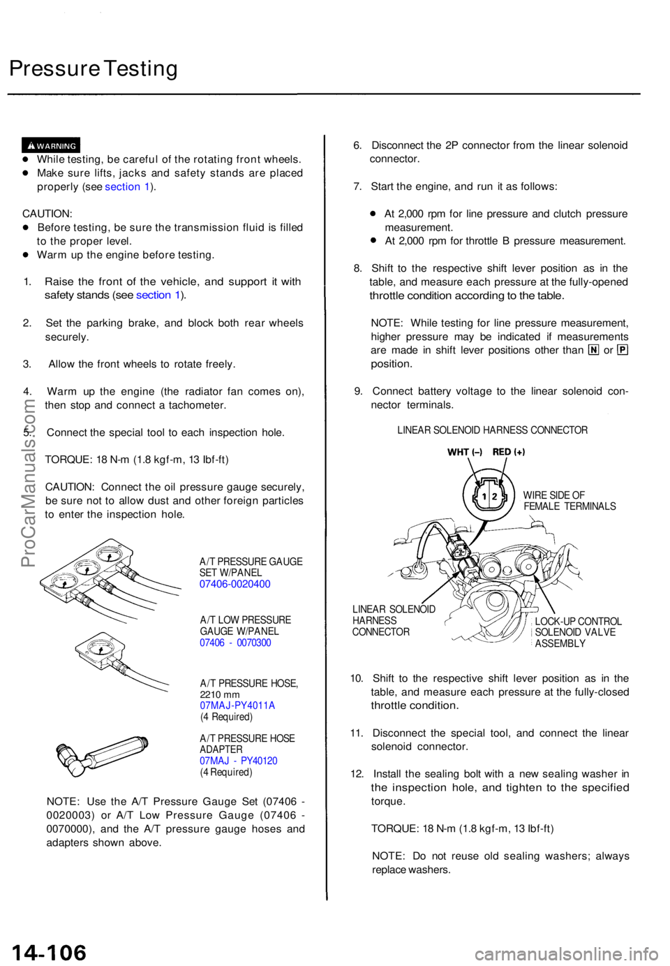
Pressure Testin g
While testing , b e carefu l o f th e rotatin g fron t wheels .
Mak e sur e lifts , jack s an d safet y stand s ar e place d
properl y (se e sectio n 1 ).
CAUTION :
Befor e testing , b e sur e th e transmissio n flui d is fille d
t o th e prope r level .
War m u p th e engin e befor e testing .
1. Rais e th e fron t o f th e vehicle , an d suppor t i t wit h
safet y stand s (se e sectio n 1 ).
2 . Se t th e parkin g brake , an d bloc k bot h rea r wheel s
securely .
3. Allo w th e fron t wheel s t o rotat e freely .
4 . War m u p th e engin e (th e radiato r fa n come s on) ,
the n sto p an d connec t a tachometer .
5 . Connec t th e specia l too l t o eac h inspectio n hole .
TORQUE : 1 8 N- m (1. 8 kgf-m , 1 3 Ibf-ft )
CAUTION : Connec t th e oi l pressur e gaug e securely ,
b e sur e no t t o allo w dus t an d othe r foreig n particle s
t o ente r th e inspectio n hole .
A/T PRESSUR E GAUG E
SE T W/PANE L
07406-002040 0
A/T LO W PRESSUR E
GAUG E W/PANE L
0740 6 - 007030 0
A/ T PRESSUR E HOSE ,
2210 mm07MAJ-PY4011 A
( 4 Required )
A/ T PRESSUR E HOS E
ADAPTE R07MAJ - PY4012 0
( 4 Required )
NOTE: Us e th e A/ T Pressur e Gaug e Se t (0740 6 -
0020003 ) o r A/ T Lo w Pressur e Gaug e (0740 6 -
0070000) , an d th e A/ T pressur e gaug e hose s an d
adapter s show n above . 6
. Disconnec t th e 2 P connecto r fro m th e linea r solenoi d
connector .
7 . Star t th e engine , an d ru n i t a s follows :
A t 2,00 0 rp m fo r lin e pressur e an d clutc h pressur e
measurement .
A t 2,00 0 rp m fo r throttl e B pressur e measurement .
8 . Shif t t o th e respectiv e shif t leve r positio n a s i n th e
table , an d measur e eac h pressur e a t th e fully-opene d
throttle conditio n accordin g to th e table .
NOTE : Whil e testin g fo r lin e pressur e measurement ,
highe r pressur e ma y b e indicate d i f measurement s
are mad e i n shif t leve r position s othe r tha n o r
position .
9. Connec t batter y voltag e t o th e linea r solenoi d con -
necto r terminals .
LINEAR SOLENOI D HARNES S CONNECTO R
WIR E SID E O F
FEMAL E TERMINAL S
LINEA R SOLENOI D
HARNES S
CONNECTO R LOCK-U
P CONTRO L
SOLENOI D VALV E
ASSEMBL Y
10. Shif t t o th e respectiv e shif t leve r positio n a s i n th e
table , an d measur e eac h pressur e a t th e fully-close d
throttle condition .
11. Disconnec t th e specia l tool , an d connec t th e linea r
solenoi d connector .
12 . Instal l th e sealin g bol t wit h a ne w sealin g washe r i n
th e inspectio n hole , an d tighte n t o th e specifie d
torque.
TORQUE : 1 8 N- m (1. 8 kgf-m , 1 3 Ibf-ft )
NOTE : D o no t reus e ol d sealin g washers ; alway s
replac e washers .
ProCarManuals.com
Page 1009 of 1771
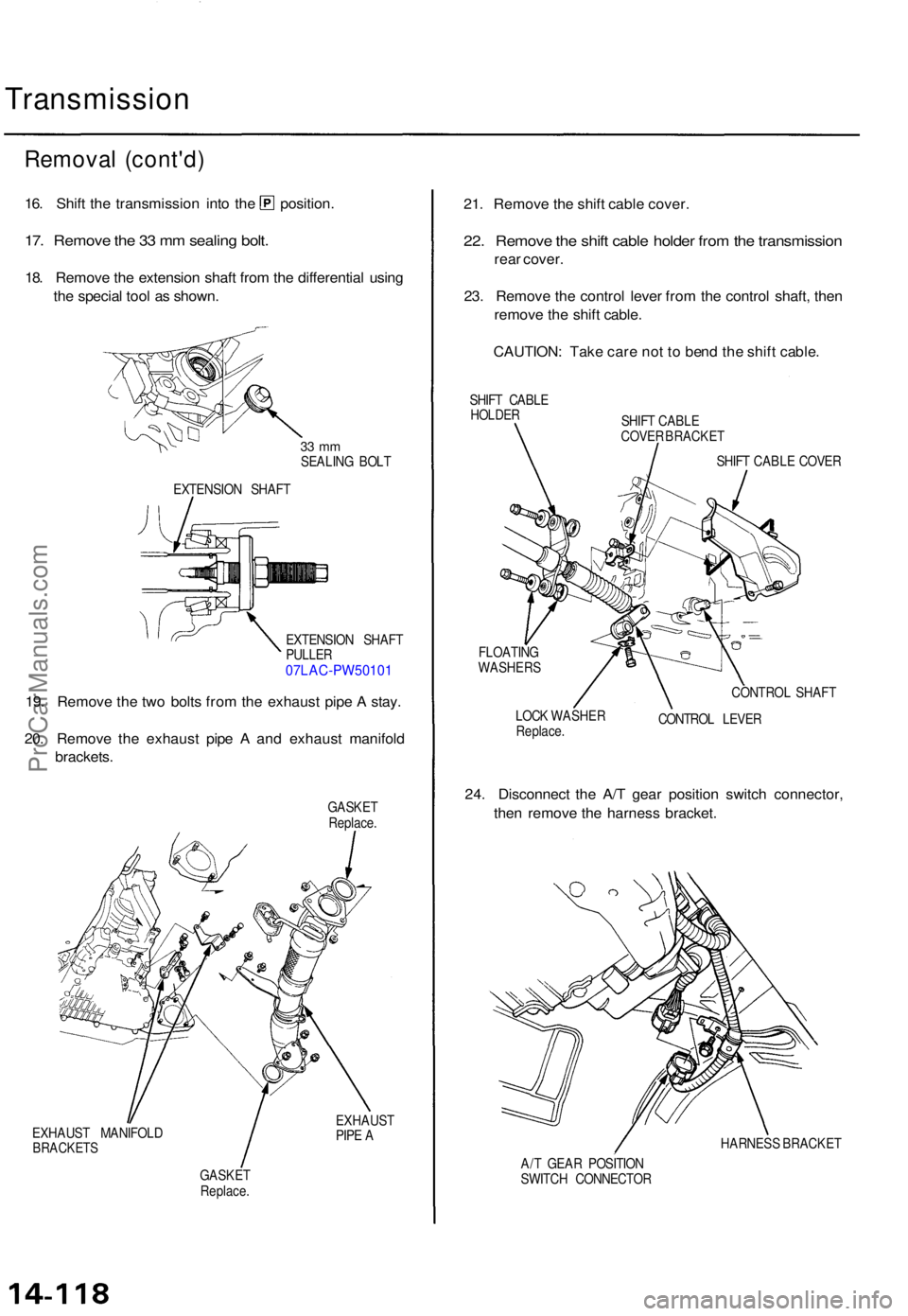
Transmission
Removal (cont'd )
16. Shif t th e transmissio n int o th e position .
17. Remov e th e 3 3 m m sealin g bolt .
18. Remov e th e extensio n shaf t fro m th e differentia l usin g
th e specia l too l a s shown .
33 m mSEALIN G BOL T
EXTENSIO N SHAF T
EXTENSIO N SHAF T
PULLE R
07LAC-PW5010 1
19. Remov e th e tw o bolt s fro m th e exhaus t pip e A stay .
20 . Remov e th e exhaus t pip e A an d exhaus t manifol d
brackets .
GASKET
Replace .
EXHAUS T MANIFOL D
BRACKETS
EXHAUST
PIP E A
GASKE T
Replace .
21. Remov e th e shif t cabl e cover .
22. Remov e th e shif t cabl e holde r fro m th e transmissio n
rear cover .
23 . Remov e th e contro l leve r fro m th e contro l shaft , the n
remov e th e shif t cable .
CAUTION : Tak e car e no t t o ben d th e shif t cable .
SHIFT CABL EHOLDE RSHIFT CABL E
COVE R BRACKE T
SHIF T CABL E COVE R
FLOATIN G
WASHER S
LOCK WASHE R
Replace . CONTRO
L SHAF T
CONTRO L LEVE R
24. Disconnec t th e A/ T gea r positio n switc h connector ,
the n remov e th e harnes s bracket .
HARNES S BRACKE T
A/ T GEA R POSITIO N
SWITC H CONNECTO R
ProCarManuals.com
Page 1014 of 1771
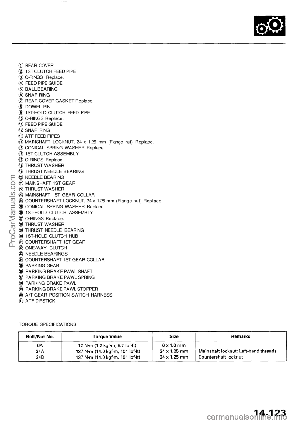
REAR COVE R
1ST CLUTC H FEE D PIP E
O-RING S Replace .
FEE D PIP E GUID E
BAL L BEARIN G
SNAP RIN G
REA R COVE R GASKE T Replace .
DOWE L PI N
1ST-HOL D CLUTC H FEE D PIP E
O-RING S Replace .
FEE D PIP E GUID E
SNA P RIN G
AT F FEE D PIPE S
MAINSHAF T LOCKNUT , 2 4 x 1.2 5 m m (Flang e nut ) Replace .
CONICA L SPRIN G WASHE R Replace .
1S T CLUTC H ASSEMBL Y
O-RING S Replace .
THRUS T WASHE R
THRUS T NEEDL E BEARIN G
NEEDL E BEARIN G
MAINSHAF T 1S T GEA R
THRUS T WASHE R
MAINSHAF T 1S T GEA R COLLA R
COUNTERSHAF T LOCKNUT , 2 4 x 1.2 5 m m (Flang e nut ) Replace .
CONICA L SPRIN G WASHE R Replace .
1ST-HOL D CLUTC H ASSEMBL Y
O-RING S Replace .
THRUS T WASHE R
THRUS T NEEDL E BEARIN G
1ST-HOL D CLUTC H HU B
COUNTERSHAF T 1S T GEA R
ONE-WA Y CLUTC H
NEEDL E BEARING S
COUNTERSHAF T 1S T GEA R COLLA R
PARKIN G GEA R
PARKIN G BRAK E PAW L SHAF T
PARKIN G BRAK E PAW L SPRIN G
PARKIN G BRAK E PAW L
PARKIN G BRAK E PAW L STOPPE R
A/ T GEA R POSITIO N SWITC H HARNES S
AT F DIPSTIC K
TORQU E SPECIFICATION S
ProCarManuals.com
Page 1021 of 1771
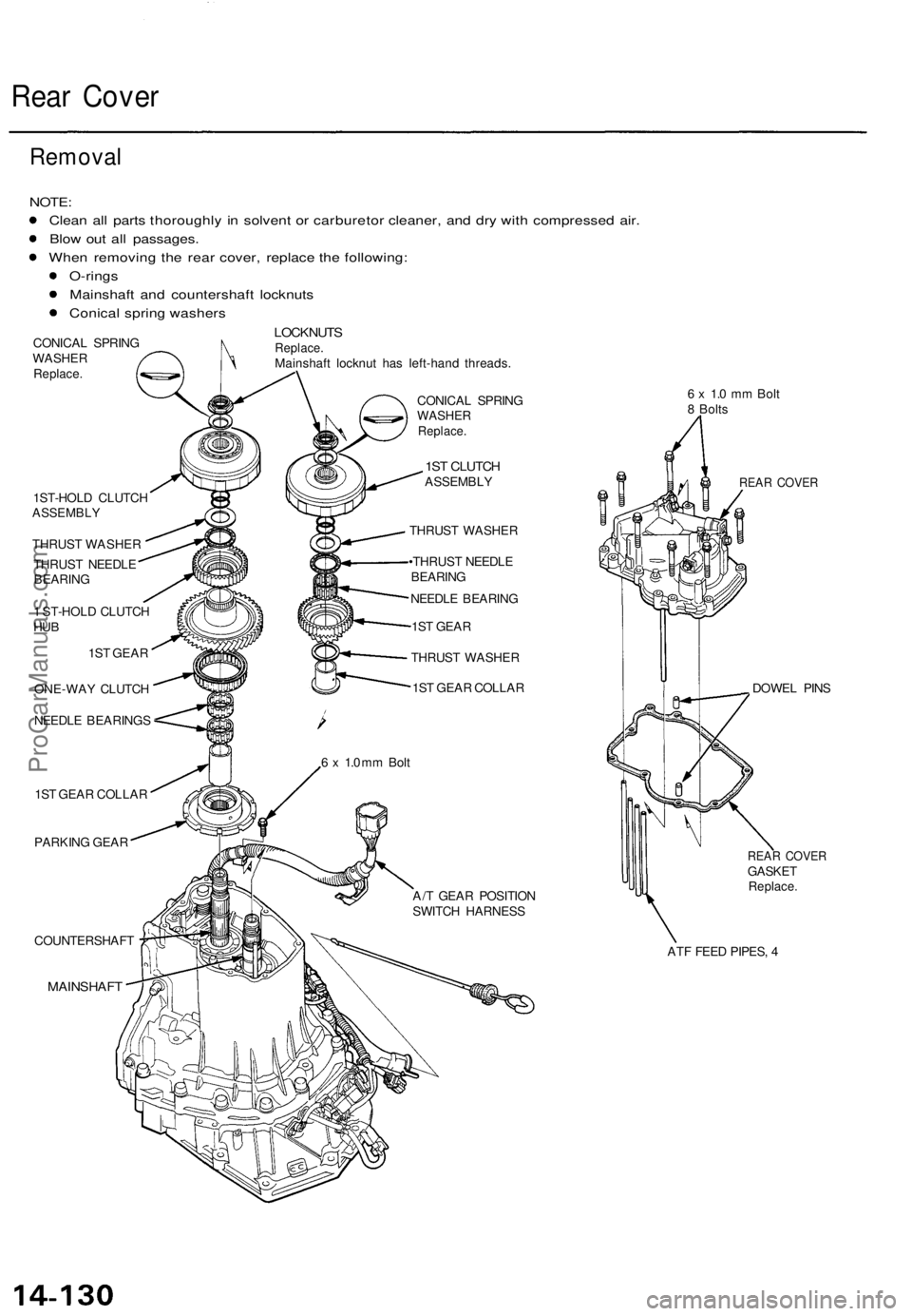
Rear Cover
Removal
NOTE:
Clean all parts thoroughly in solvent or carburetor cleaner, and dry with compressed air.
Blow out all passages.
When removing the rear cover, replace the following:
O-rings
Mainshaft and countershaft locknuts
Conical spring washers
LOCKNUTS
Replace.
Mainshaft locknut has left-hand threads.
CONICAL SPRING
WASHER
Replace.
1ST-HOLD CLUTCH
ASSEMBLY
THRUST WASHER
THRUST NEEDLE
BEARING
1 ST-HOLD CLUTCH
HUB
1ST GEAR
ONE-WAY CLUTCH
NEEDLE BEARINGS
1ST GEAR COLLAR
PARKING GEAR
COUNTERSHAFT
MAINSHAFT
CONICAL SPRING
WASHER
Replace.
1ST CLUTCH
ASSEMBLY
THRUST WASHER
•THRUST NEEDLE
BEARING
NEEDLE BEARING
1ST GEAR
THRUST WASHER
1ST GEAR COLLAR
6 x 1.0 mm Bolt
8 Bolts
REAR COVER
DOWEL PINS
REAR COVER
GASKET
Replace.
ATF FEED PIPES, 4
A/T GEAR POSITION
SWITCH HARNESS
6 x 1.0 mm BoltProCarManuals.com