Page 1088 of 1771
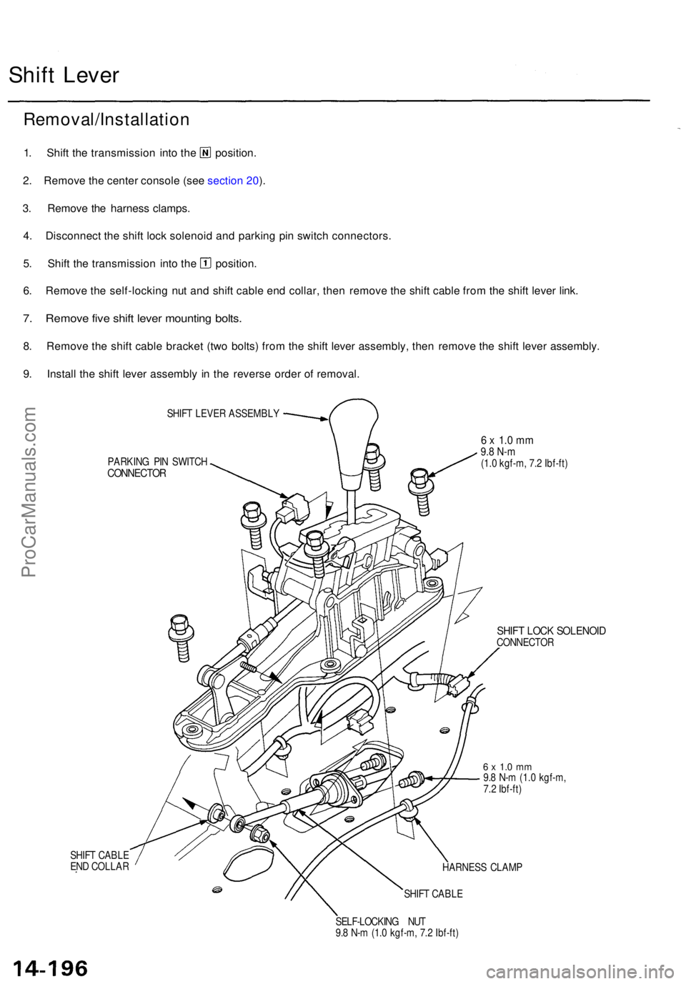
Shift Leve r
Removal/Installatio n
1. Shif t th e transmissio n int o th e position .
2 . Remov e th e cente r consol e (se e sectio n 20 ).
3 . Remov e th e harnes s clamps .
4 . Disconnec t th e shif t loc k solenoi d an d parkin g pi n switc h connectors .
5. Shif t th e transmissio n int o th e position .
6 . Remov e th e self-lockin g nu t an d shif t cabl e en d collar , the n remov e th e shif t cabl e fro m th e shif t leve r link .
7. Remov e fiv e shif t leve r mountin g bolts .
8. Remov e th e shif t cabl e bracke t (tw o bolts ) fro m th e shif t leve r assembly , the n remov e th e shif t leve r assembly .
9 . Instal l th e shif t leve r assembl y i n th e revers e orde r o f removal .
SHIFT LEVE R ASSEMBL Y
PARKIN G PI N SWITC H
CONNECTO R
SHIFT CABL E
EN D COLLA R
6 x 1. 0 m m9.8 N- m(1.0 kgf-m , 7. 2 Ibf-ft )
SHIFT LOC K SOLENOI DCONNECTO R
6 x 1. 0 m m9.8 N- m (1. 0 kgf-m ,
7. 2 Ibf-ft )
HARNES S CLAM P
SHIF T CABL E
SELF-LOCKIN G NU T
9. 8 N- m (1. 0 kgf-m , 7. 2 Ibf-ft )
ProCarManuals.com
Page 1089 of 1771
Disassembly
SHIFT LEVER KNOB
SHIFT LOCK
RELEASE LEVER
LEVER COVER
SHIFT LOCK
STOPPER
6 x 1.0 mm
9.8 N-m (1.0 kgf-m,
7.2 Ibf-ft)
SHIFT LOCK SOLENOID
6 x 1.0 mm
8 N-m (0.8 kgf-m, 6 Ibf-ft)
A/T GEAR POSITION
PANEL
LOCK PIN
LINK ADJUSTER
LOCKNUT
7 N-m (0.7 kgf-m, 5 Ibf-ft)
BRACKET BASE
CONTROL SEAL
PARKING PIN SWITCH
5 x 0.8 mm
4 N-m (0.4 kgf-m, 3 Ibf-ft)
COLLAR
RUBBERProCarManuals.com
Page 1090 of 1771
Shift Leve r
Link Adjustmen t
Make sur e lifts , jack s an d safet y stand s ar e place d
properl y (se e sectio n 1 ).
Appl y parkin g brake , an d bloc k rea r wheel s s o vehi -
cl e wil l no t rol l of f stand s an d fal l o n yo u whil e work -
in g unde r it .
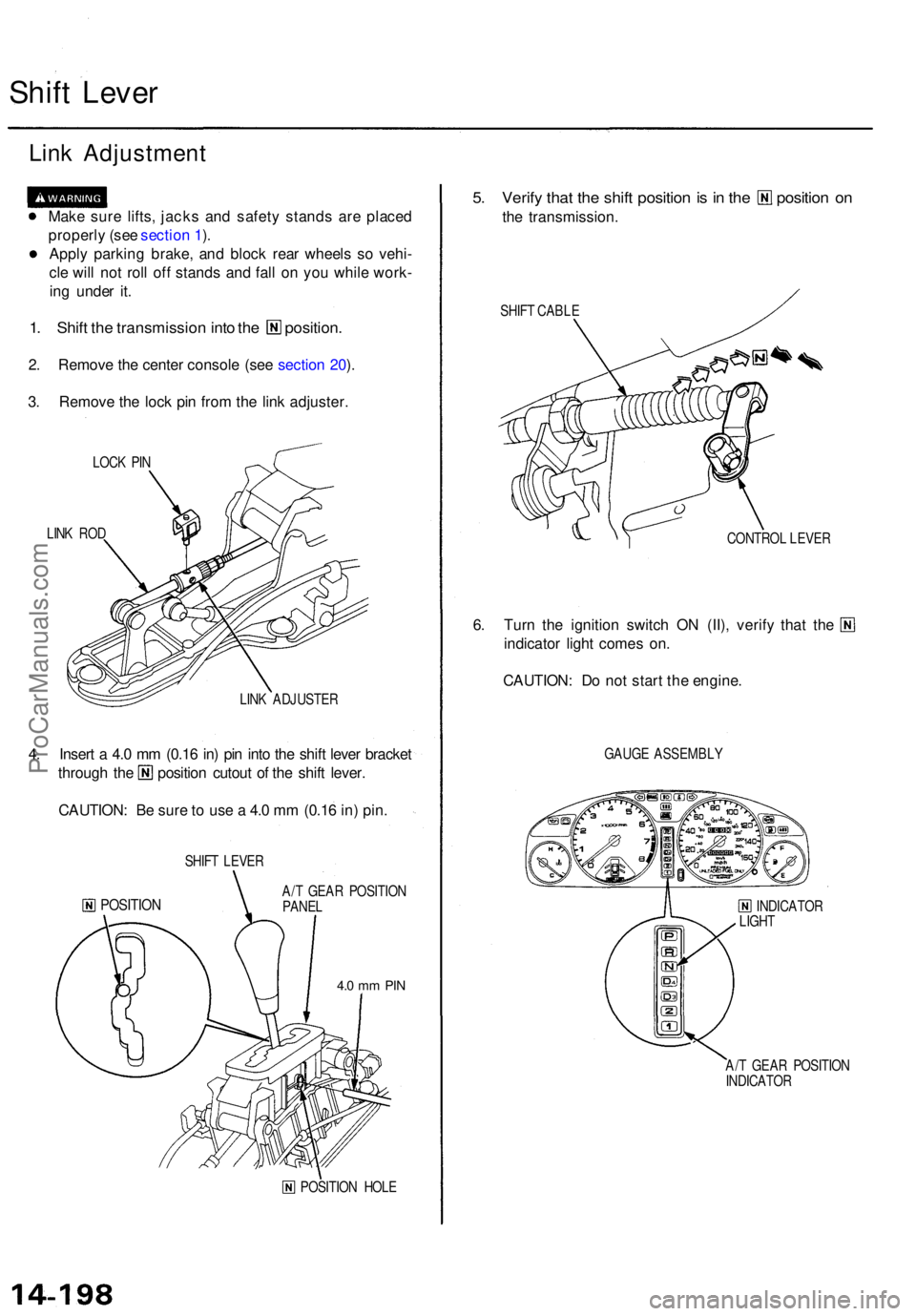
1. Shif t th e transmissio n int o th e position .
2. Remov e th e cente r consol e (se e sectio n 20 ).
3 . Remov e th e loc k pi n fro m th e lin k adjuster .
LOCK PI N
LIN K RO D
LINK ADJUSTE R
4. Inser t a 4. 0 m m (0.1 6 in ) pi n int o th e shif t leve r bracke t
through th e positio n cutou t o f th e shif t lever .
CAUTION : B e sur e to us e a 4. 0 m m (0.1 6 in ) pin .
SHIF T LEVE R
POSITIO NA/T GEA R POSITIO N
PANE L
4.0 m m PI N
POSITIO N HOL E
5. Verif y tha t th e shif t positio n is i n th e positio n o n
the transmission .
SHIFT CABL E
CONTROL LEVE R
6. Tur n th e ignitio n switc h O N (II) , verif y tha t th e
indicator light come s on .
CAUTION : D o no t star t th e engine .
GAUGE ASSEMBL Y
INDICATO R
LIGH T
A/ T GEA R POSITIO N
INDICATO R
ProCarManuals.com
Page 1091 of 1771
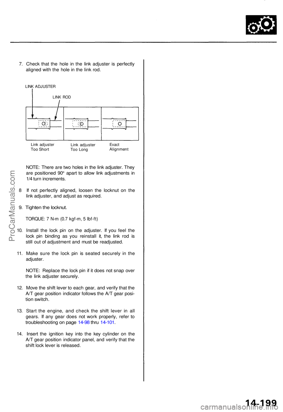
7. Chec k tha t th e hol e i n th e lin k adjuste r i s perfectl y
aligne d wit h th e hol e in th e lin k rod .
LINK ADJUSTE R
LINK RO D
Link adjuste rToo Shor tLink adjuste rToo Lon gExac tAlignmen t
NOTE: Ther e ar e tw o hole s in th e lin k adjuster . The y
ar e positione d 90 ° apar t t o allo w lin k adjustment s i n
1/ 4 tur n increments .
8 I f no t perfectl y aligned , loose n th e locknu t o n th e
lin k adjuster , an d adjus t a s required .
9. Tighte n th e locknut .
TORQUE : 7 N- m (0. 7 kgf-m , 5 Ibf-ft )
10. Instal l th e loc k pi n o n th e adjuster . I f yo u fee l th e
loc k pi n bindin g a s yo u reinstal l it , th e lin k ro d i s
stil l ou t o f adjustmen t an d mus t b e readjusted .
11 . Mak e sur e th e loc k pi n i s seate d securel y i n th e
adjuster .
NOTE : Replac e th e loc k pi n if i t doe s no t sna p ove r
th e lin k adjuste r securely .
12 . Mov e th e shif t leve r t o eac h gear , an d verif y tha t th e
A/ T gea r positio n indicato r follow s th e A/ T gea r posi -
tion switch .
13. Star t th e engine , an d chec k th e shif t leve r i n al l
gears . I f an y gea r doe s no t wor k properly , refe r t o
troubleshootin g o n pag e 14-9 8 thr u 14-101 .
14. Inser t th e ignitio n ke y int o th e ke y cylinde r o n th e
A/ T gea r positio n indicato r panel , an d verif y tha t th e
shif t loc k leve r i s released .
ProCarManuals.com
Page 1092 of 1771
Shift Cabl e
Replacemen t
Make sur e th e lifts , jack s an d safet y stand s ar e place d
properl y (se e sectio n 1 ).
Appl y parkin g brake , an d bloc k rea r wheel s s o th e
vehicl e wil l no t rol l of f stand s an d fal l o n yo u whil e
workin g unde r it .
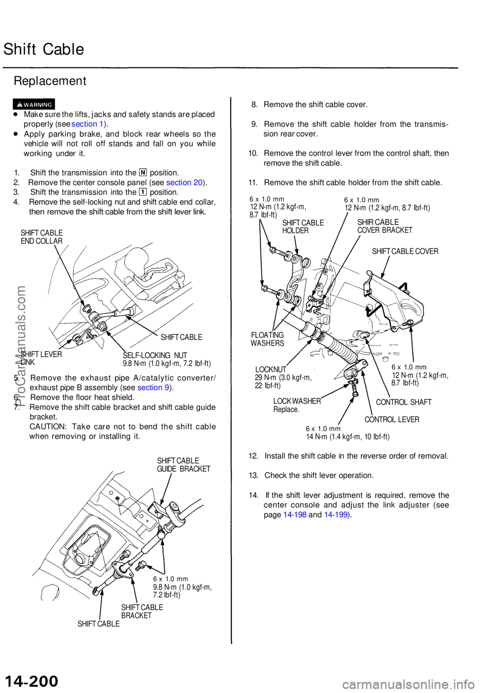
1. Shif t th e transmissio n int o th e position .
2 . Remov e th e cente r consol e pane l (se e sectio n 20 ).
3 . Shif t th e transmissio n int o th e position .
4 . Remov e th e self-lockin g nu t an d shif t cabl e en d collar ,
then remov e th e shif t cabl e fro m th e shif t leve r link .
SHIF T CABL E
EN D COLLA R
SHIF T LEVE R
LIN K SHIF
T CABL E
SELF-LOCKIN G NU T
9. 8 N- m (1. 0 kgf-m , 7. 2 Ibf-ft )
5. Remov e th e exhaus t pip e A/catalyti c converter /
exhaus t pip e B assembl y (se e sectio n 9 ).
6 . Remov e th e floo r hea t shield .
7 . Remov e th e shif t cabl e bracke t an d shif t cabl e guid e
bracket .
CAUTION : Tak e car e no t t o ben d th e shif t cabl e
whe n removin g o r installin g it .
SHIF T CABL E
GUID E BRACKE T
6 x 1. 0 m m9.8 N- m (1. 0 kgf-m ,
7. 2 Ibf-ft )
SHIF T CABL E
BRACKE TSHIFT CABL E
8. Remov e th e shif t cabl e cover .
9 . Remov e th e shif t cabl e holde r fro m th e transmis -
sio n rea r cover .
10 . Remov e th e contro l leve r fro m th e contro l shaft , the n
remov e th e shif t cable .
11 . Remov e th e shif t cabl e holde r fro m th e shif t cable .
6 x 1. 0 m m12 N- m (1. 2 kgf-m ,
8. 7 Ibf-ft )
SHIF T CABL E
HOLDE R
6 x 1. 0 m m12 N- m (1. 2 kgf-m , 8. 7 Ibf-ft )
SHIR CABL ECOVER BRACKE T
SHIFT CABL E COVE R
FLOATIN G
WASHER S
LOCKNUT
2 9 N- m (3. 0 kgf-m ,
2 2 Ibf-ft )
LOC K WASHE R
Replace .
6 x 1. 0 m m12 N- m (1. 2 kgf-m ,
8. 7 Ibf-ft )
CONTRO L SHAF T
CONTRO L LEVE R
6 x 1. 0 m m14 N- m (1. 4 kgf-m , 1 0 Ibf-ft )
12. Instal l th e shif t cabl e in th e revers e orde r o f removal .
13 . Chec k th e shif t leve r operation .
14 . I f th e shif t leve r adjustmen t i s required , remov e th e
cente r consol e an d adjus t th e lin k adjuste r (se e
pag e 14-19 8 an d 14-199 ).
ProCarManuals.com
Page 1099 of 1771
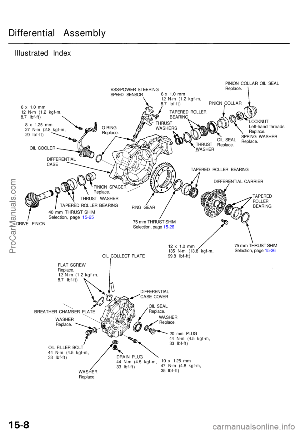
Differential Assembl y
Illustrated Inde x
VSS/POWE R STEERIN G
SPEE D SENSO R PINIO
N COLLA R OI L SEA L
Replace .
6 x 1. 0 m m12 N- m (1. 2 kgf-m ,
8. 7 Ibf-ft )
8 x 1.2 5 mm27 N- m (2. 8 kgf-m ,
2 0 Ibf-ft )
OI L COOLE R
6 x 1. 0 m m12 N- m (1. 2 kgf-m ,
8. 7 Ibf-ft )
LOCKNUT
Left-hand thread sReplace .
SPRIN G WASHE R
Replace.
DIFFERENTIA LCASE
PINIO N SPACE R
Replace .
THRUS T WASHE R
TAPERE D ROLLE R BEARIN G
40 m m THRUS T SHI MSelection , pag e 15-2 5
TAPERE D ROLLE R BEARIN G
DIFFERENTIA L CARRIE R
DRIV E PINIO N
75 m m THRUS T SHI MSelection , pag e 15-2 6
OIL COLLEC T PLAT E
12 x 1. 0 m m135 N- m (13. 8 kgf-m ,
99. 8 Ibf-ft )
TAPERE DROLLERBEARIN G
75 m m THRUS T SHI MSelection , pag e 15-2 6
FLA T SCRE W
Replace .
12 N- m (1. 2 kgf-m ,8.7 Ibf-ft )
BREATHE R CHAMBE R PLAT E
WASHE R
Replace .
OI L FILLE R BOL T
4 4 N- m (4. 5 kgf-m ,
3 3 Ibf-ft )
WASHE R
Replace . DIFFERENTIA
L
CAS E COVE R
OI L SEA L
Replace .
WASHE R
Replace .
DRAI N PLU G
4 4 N- m (4. 5 kgf-m ,
3 3 Ibf-ft ) 2
0 m m PLU G
4 4 N- m (4. 5 kgf-m ,
3 3 Ibf-ft )
10 x 1.2 5 mm47 N- m (4. 8 kgf-m ,
3 5 Ibf-ft ) OI
L SEA L
Replace .
THRUS
T
WASHE R
PINIO
N COLLA R
TAPERE D ROLLE RBEARING
O-RIN G
Replace .
THRUST
WASHER S
RIN G GEA R
ProCarManuals.com
Page 1103 of 1771
Differential Assembl y
Disassembl y (cont'd )
5. Remov e th e differentia l carrie r fro m th e differentia l
case.
DIFFERENTIA L CARRIE R
DIFFERENTIA L
CAS E
6. Remov e th e oi l cooler .
OIL COOLE R
O-RINGReplace .
DIFFERENTIA L
CAS E
7. Rais e th e locknu t ta b fro m th e groov e of the driv e
pinion .
CAUTION : Mak e sur e tha t th e ta b completel y clear s
the groov e t o preven t damagin g th e driv e pinio n
threads .
TAB
8. Hol d th e driv e pinio n usin g a 1 1/4 " (3 2 mm ) he x
bi t an d socke t a s shown .
1 1/4 " (3 2 mm ) HE X BI T an d SOCKE T
(Commerciall y available )
ProCarManuals.com
Page 1104 of 1771
9. Remov e th e locknu t an d th e sprin g washe r fro m th e
driv e pinion .
NOTE : Th e locknu t ha s left-han d threads .
LOCKNU T
Replace .
SPRIN G WASHE R
DRIV E PINIO N
10. Remov e th e pinio n colla r an d th e oi l seal , the n ta p
th e driv e pinio n throug h th e tapere d rolle r bearing .
PINION COLLA R
OI L SEA L
Replace .
TAPERE D ROLLE R
BEARIN G
DRIV E PINIO N
11. Remov e th e driv e pinion , th e pinio n spacer , an d th e
thrus t washers .
THRUST WASHER S
PINIO N SPACE R
Replace.
DRIVE PINIO N
DIFFERENTIA L
CAS E
12. Remov e th e tapere d rolle r bearin g an d 4 0 m m thrus t
shi m usin g a pres s a s shown .
PRESS
BEARIN GSEPARATOR ,0-4 1/ 2 in .(Commerciall y available )
TAPERE
D
ROLLERBEARIN G
40 m m THRUS TSHIM
ProCarManuals.com