Page 1044 of 1771
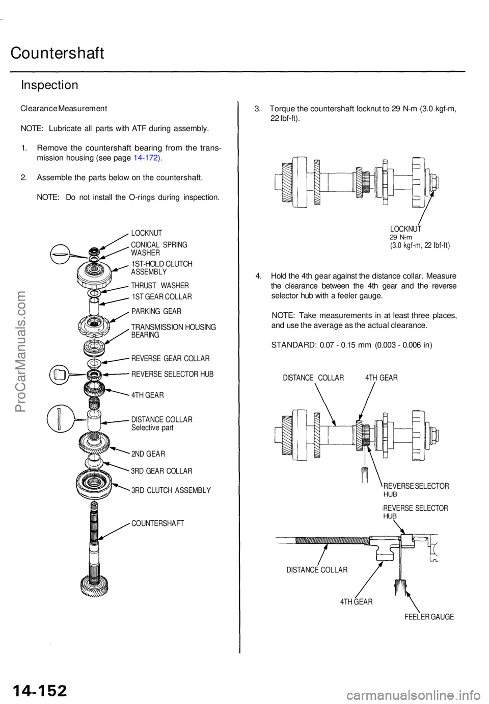
Countershaft
Inspection
Clearance Measuremen t
NOTE : Lubricat e al l part s wit h AT F durin g assembly .
1. Remov e th e countershaf t bearin g fro m th e trans -
missio n housin g (se e pag e 14-172 ).
2 . Assembl e th e part s belo w o n th e countershaft .
NOTE : D o no t instal l th e O-ring s durin g inspection .
LOCKNUT
CONICA L SPRIN G
WASHE R
1ST-HOL D CLUTC HASSEMBL Y
THRUS T WASHE R
1S T GEA R COLLA R
PARKIN G GEA R
TRANSMISSIO N HOUSIN GBEARING
REVERS E GEA R COLLA R
REVERS E SELECTO R HU B
4T H GEA R
3. Torqu e th e countershaf t locknu t t o 2 9 N- m (3. 0 kgf-m ,
2 2 Ibf-ft) .
LOCKNU T29 N- m(3.0 kgf-m , 2 2 Ibf-ft )
4. Hol d th e 4t h gea r agains t th e distanc e collar . Measur e
th e clearanc e betwee n th e 4t h gea r an d th e revers e
selecto r hu b wit h a feele r gauge .
NOTE : Tak e measurement s i n a t leas t thre e places ,
an d us e th e averag e a s th e actua l clearance .
STANDARD : 0.0 7 - 0.1 5 m m (0.00 3 - 0.00 6 in )
DISTANC E COLLA R 4T H GEA R
4T H GEA R
FEELER GAUG E
REVERS
E SELECTO R
HUB
REVERS E SELECTO RHUB
DISTANC E COLLA R
DISTANC
E COLLA R
Selective par t
2ND GEA R
3R D GEA R COLLA R
3R D CLUTC H ASSEMBL Y
COUNTERSHAF T
ProCarManuals.com
Page 1068 of 1771
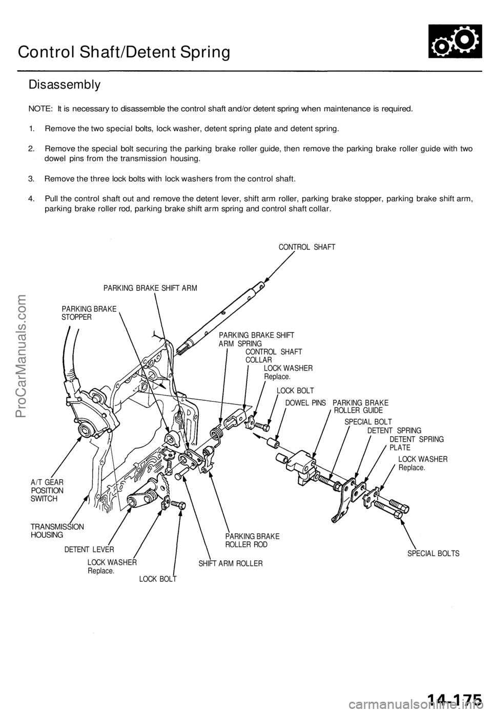
Control Shaft/Detent Spring
Disassembly
NOTE: It is necessary to disassemble the control shaft and/or detent spring when maintenance is required.
1. Remove the two special bolts, lock washer, detent spring plate and detent spring.
2. Remove the special bolt securing the parking brake roller guide, then remove the parking brake roller guide with two
dowel pins from the transmission housing.
3. Remove the three lock bolts with lock washers from the control shaft.
4. Pull the control shaft out and remove the detent lever, shift arm roller, parking brake stopper, parking brake shift arm,
parking brake roller rod, parking brake shift arm spring and control shaft collar.
CONTROL SHAFT
PARKING BRAKE SHIFT ARM
PARKING BRAKE
STOPPER
DOWEL PINS PARKING BRAKE
ROLLER GUIDE
A/T GEAR
POSITION
SWITCH
TRANSMISSION
HOUSING
DETENT LEVER
LOCK WASHER
Replace.
SHIFT ARM ROLLER
SPECIAL BOLT
DETENT SPRING
DETENT SPRING
PLATE
LOCK WASHER
Replace.
SPECIAL BOLTS
LOCK BOLT
PARKING BRAKE
ROLLER ROD
LOCK BOLT
LOCK WASHER
Replace.
CONTROL SHAFT
COLLAR
PARKING BRAKE SHIFT
ARM SPRINGProCarManuals.com
Page 1069 of 1771
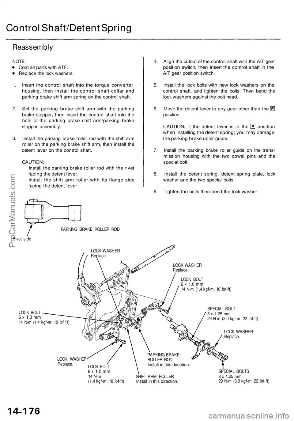
Control Shaft/Deten t Sprin g
Reassembl y
NOTE:
Coat al l part s wit h ATF .
Replac e th e loc k washers .
1. Inser t th e contro l shaf t int o th e torqu e converte r
housing, the n instal l th e contro l shaf t colla r an d
parkin g brak e shif t ar m sprin g o n th e contro l shaft .
2 . Se t th e parkin g brak e shif t ar m wit h th e parkin g
brak e stopper , the n inser t th e contro l shaf t int o th e
hol e o f th e parkin g brak e shif t arm/parkin g brak e
stoppe r assembly .
3 . Instal l th e parkin g brak e rolle r ro d wit h th e shif t ar m
rolle r o n th e parkin g brak e shif t arm , the n instal l th e
deten t leve r o n th e contro l shaft .
CAUTION :
Instal l th e parkin g brak e rolle r ro d wit h th e rive t
facin g th e deten t lever .
Instal l th e shif t ar m rolle r wit h it s flang e sid e
facin g th e deten t lever .
Rivet sid e PARKIN
G BRAK E ROLLE R RO D
LOC K WASHE R
Replace.
LOCK BOL T6 x 1. 0 m m14 N- m (1. 4 kgf-m , 1 0 Ib f ft )
4. Alig n th e cutou t o f th e contro l shaf t wit h th e A/ T gea r
positio n switch , the n inser t th e contro l shaf t i n th e
A/T gea r positio n switch .
5. Instal l th e loc k bolt s wit h ne w loc k washer s o n th e
contro l shaft , an d tighte n th e bolts . The n ben d th e
loc k washer s agains t th e bol t head .
6. Mov e th e deten t leve r t o an y gea r othe r tha n th e
position .
CAUTION : I f th e deten t leve r i s i n th e positio n
when installin g th e deten t spring ; yo u ma y damag e
the parkin g brak e rolle r guide .
7 . Instal l th e parkin g brak e rolle r guid e o n th e trans -
missio n housin g wit h th e tw o dowe l pin s an d th e
specia l bolt .
8 . Instal l th e deten t spring , deten t sprin g plate , loc k
washe r an d th e tw o specia l bolts .
9 . Tighte n th e bolt s the n ben d th e loc k washer .
LOCK WASHE RReplace.
LOCK BOL T6 x 1. 0 m m14 N- m (1. 4 kgf-m , 1 0 Ibf-ft )
LOC K WASHE R
Replace.LOCK BOL T6 x 1. 0 m m14 N- m(1.4 kgf-m , 1 0 Ibf-ft ) SPECIA
L BOL T
8 x 1.2 5 mm29 N- m (3. 0 kgf-m , 2 2 Ibf-ft )
LOC K WASHE R
Replace.
PARKING BRAK E
ROLLE R RO D
Instal l i n thi s directio n
SHIFT AR M ROLLE RInstall i n thi s direction .
SPECIAL BOLT S8 x 1.2 5 mm29 N- m (3. 0 kgf-m , 2 2 Ibf-ft )
ProCarManuals.com
Page 1070 of 1771
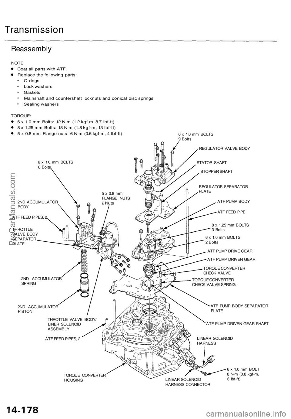
Transmission
Reassembly
NOTE:
Coat all parts with ATF.
Replace the following parts:
O-rings
Lock washers
Gaskets
Mainshaft and countershaft locknuts and conical disc springs
Sealing washers
TORQUE:
6 x 1.0 mm Bolts: 12 N-m (1.2 kgf-m, 8.7 Ibf-ft)
8 x 1.25 mm Bolts: 18 N-m (1.8 kgf-m, 13 Ibf-ft)
5 x 0.8 mm Flange nuts: 6 N-m (0.6 kgf-m, 4 Ibf-ft)
6 x 1.0 mm BOLTS
6 Bolts
6 x 1.0 mm BOLTS
9 Bolts
2ND ACCUMULATOR
BODY
ATF FEED PIPES, 2.
THROTTLE
VALVE BODY
SEPARATOR
PLATE
2ND ACCUMULATOR
SPRING
2ND ACCUMULATOR
PISTON
THROTTLE VALVE BODY/
LINER SOLENOID
ASSEMBLY
ATF FEED PIPES, 2
REGULATOR VALVE BODY
STATOR SHAFT
STOPPER SHAFT
REGULATOR SEPARATOR
PLATE
ATF PUMP BODY
ATF FEED PIPE
8 x 1.25 mm BOLTS
3 Bolts
6 x 1.0 mm BOLTS
2 Bolts
ATF PUMP DRIVE GEAR
ATF PUMP DRIVEN GEAR
TORQUE CONVERTER
CHECK VALVE
TORQUE CONVERTER
CHECK VALVE SPRING
ATF PUMP BODY SEPARATOR
PLATE
ATF PUMP DRIVEN GEAR SHAFT
LINEAR SOLENOID
HARNESS
TORQUE CONVERTER
HOUSING
LINEAR SOLENOID
HARNESS CONNECTOR
6 x 1.0 mm BOLT
8 N-m (0.8 kgf-m,
6 Ibf-ft)
5 x 0.8 mm
FLANGE NUTS
2 NutsProCarManuals.com
Page 1074 of 1771
Transmission
Reassembly (cont'd)
LOCKNUTS
Replace.
Mainshaft locknut has left-hand threads.
CONICAL SPRING WASHER
Replace.
1ST-HOLD CLUTCH
ASSEMBLY
THRUST WASHER
THRUST NEEDLE BEARING
1ST-HOLD CLUTCH HUB
1ST GEAR
ONE-WAY CLUTCH
NEEDLE BEARINGS
1ST GEAR COLLAR
PARKING GEAR
COUNTERSHAFT
MAINSHAFT
CONICAL SPRING WASHER
Replace.
1ST CLUTCH ASSEMBLY
THRUST WASHER
THRUST NEEDLE BEARING
NEEDLE BEARING
1ST GEAR
THRUST WASHER
1ST GEAR COLLAR
A/T GEAR POSITION
SWITCH HARNESSProCarManuals.com
Page 1075 of 1771
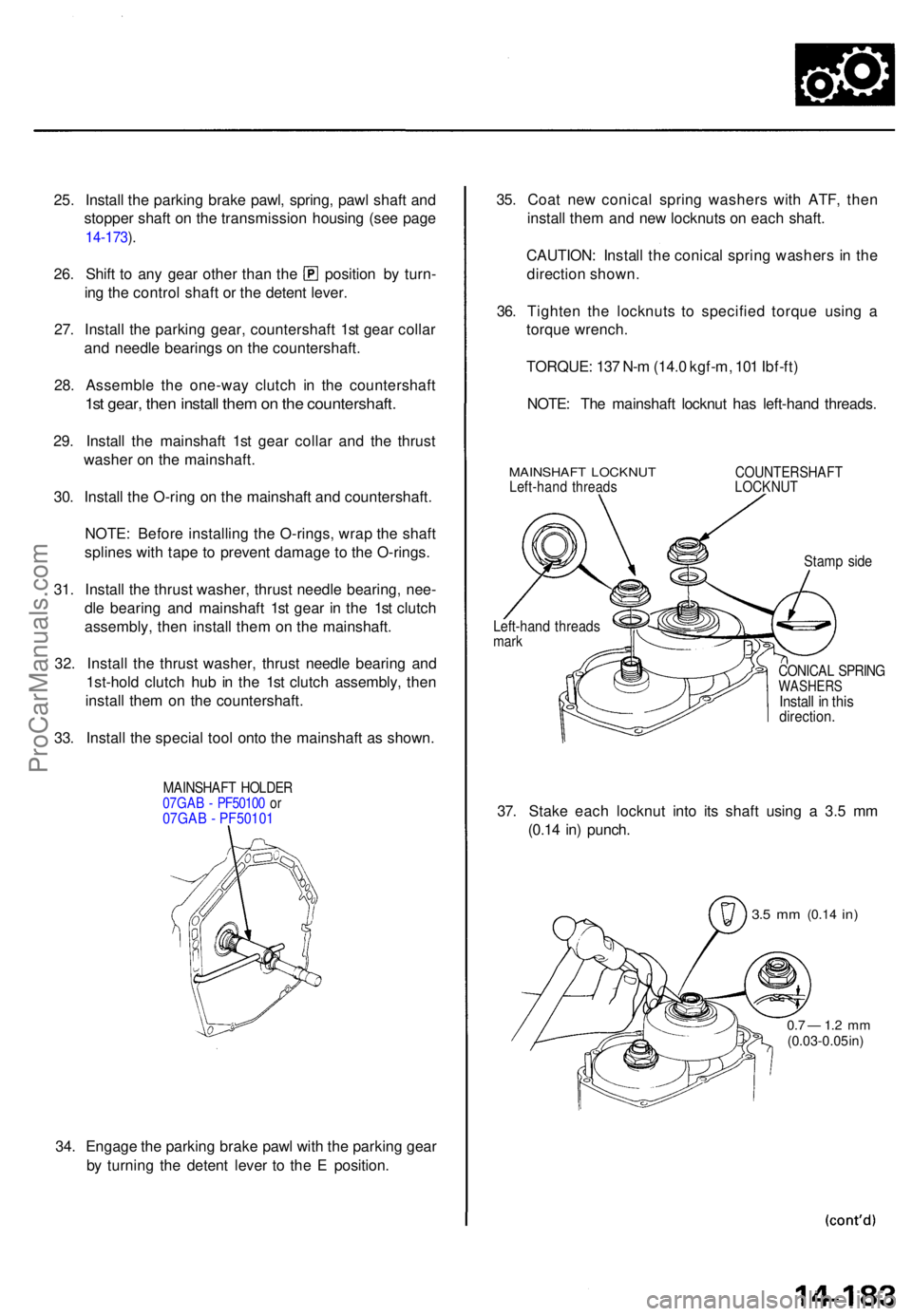
25. Instal l th e parkin g brak e pawl , spring , paw l shaf t an d
stoppe r shaf t o n th e transmissio n housin g (se e pag e
14-173 ).
26 . Shif t t o an y gea r othe r tha n th e positio n b y turn -
in g th e contro l shaf t o r th e deten t lever .
27 . Instal l th e parkin g gear , countershaf t 1s t gea r colla r
an d needl e bearing s o n th e countershaft .
28 . Assembl e th e one-wa y clutc h i n th e countershaf t
1st gear , the n instal l the m on th e countershaft .
29. Instal l th e mainshaf t 1s t gea r colla r an d th e thrus t
washe r o n th e mainshaft .
30 . Instal l th e O-rin g o n th e mainshaf t an d countershaft .
NOTE : Befor e installin g th e O-rings , wra p th e shaf t
spline s wit h tap e t o preven t damag e t o th e O-rings .
31 . Instal l th e thrus t washer , thrus t needl e bearing , nee -
dl e bearin g an d mainshaf t 1s t gea r i n th e 1s t clutc h
assembly , the n instal l the m o n th e mainshaft .
32 . Instal l th e thrus t washer , thrus t needl e bearin g an d
1st-hol d clutc h hu b i n th e 1s t clutc h assembly , the n
instal l the m o n th e countershaft .
33 . Instal l th e specia l too l ont o th e mainshaf t a s shown .
MAINSHAF T HOLDE R07GAB - PF5010 0 o r07GAB - PF50101
34 . Engag e th e parkin g brak e paw l wit h th e parkin g gea r
b y turnin g th e deten t leve r t o th e E position . 35
. Coa t ne w conica l sprin g washer s wit h ATF , the n
instal l the m an d ne w locknuts on eac h shaft .
CAUTION : Instal l th e conica l sprin g washer s in th e
directio n shown .
36 . Tighte n th e locknut s t o specifie d torqu e usin g a
torqu e wrench .
TORQUE : 13 7 N- m (14. 0 kgf-m , 10 1 Ibf-ft )
NOTE : Th e mainshaf t locknu t ha s left-han d threads .
MAINSHAF T LOCKNU TLeft-hand thread sCOUNTERSHAF TLOCKNUT
Stamp sid e
CONICA L SPRIN GWASHER SInstall i n thi sdirection .
37. Stak e eac h locknu t int o it s shaf t usin g a 3. 5 m m
(0.1 4 in ) punch .
3.5 m m (0.1 4 in)
0.7 — 1. 2 m m(0.03-0.0 5 in )
Left-han d thread smark
ProCarManuals.com
Page 1082 of 1771
Transmission
Installation (cont'd )
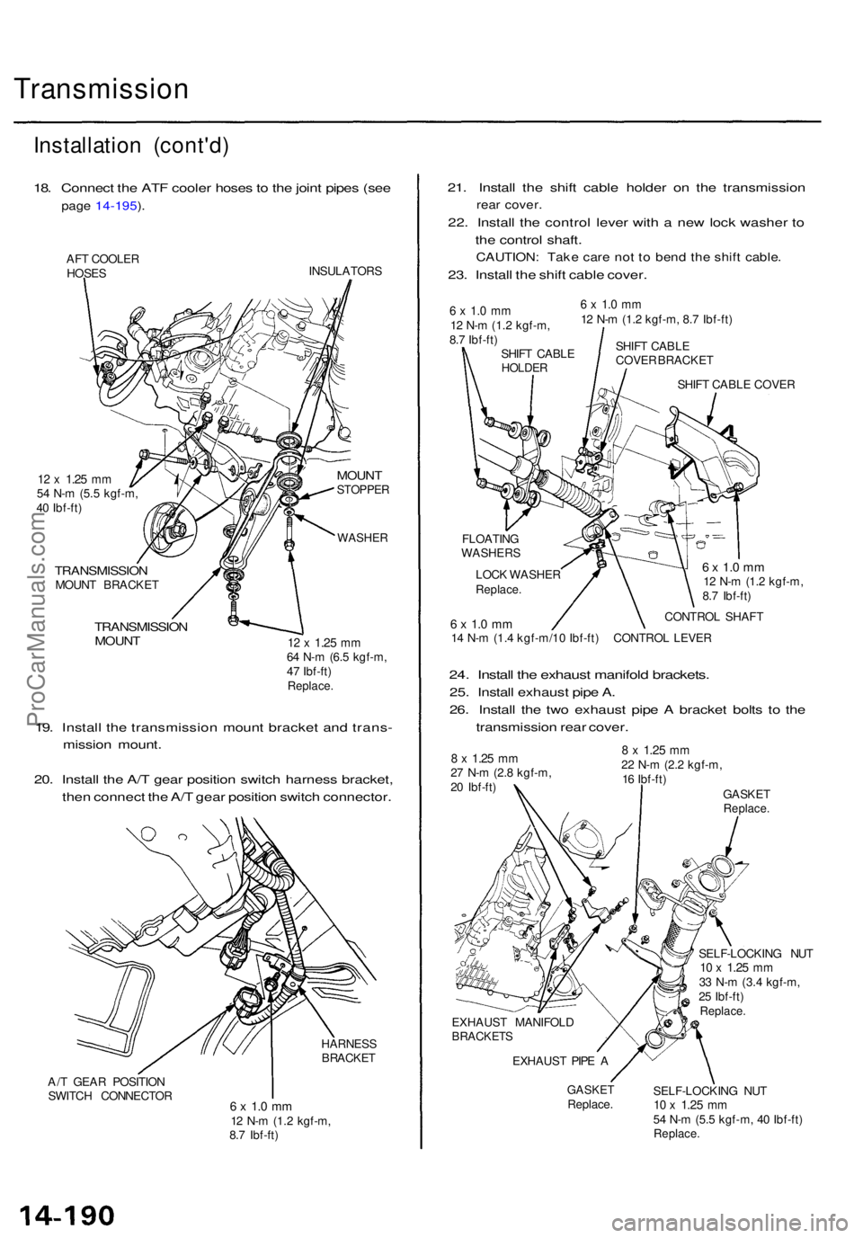
18. Connec t th e AT F coole r hose s t o th e join t pipe s (se e
pag e 14-195 ).
AF T COOLE R
HOSE S INSULATOR
S
12 x 1.2 5 mm54 N- m (5. 5 kgf-m ,
4 0 Ibf-ft )
TRANSMISSIO NMOUNT BRACKE T
TRANSMISSIO NMOUNT
MOUN TSTOPPE R
WASHER
12 x 1.2 5 mm64 N- m (6. 5 kgf-m ,
4 7 Ibf-ft )
Replace .
19. Instal l th e transmissio n moun t bracke t an d trans -
missio n mount .
20 . Instal l th e A/ T gea r positio n switc h harnes s bracket ,
the n connec t th e A/ T gea r positio n switc h connector .
HARNESS
BRACKE T
A/ T GEA R POSITIO N
SWITC H CONNECTO R
6 x 1. 0 m m12 N- m (1.2 kgf-m ,
8. 7 Ibf-ft )
21. Instal l th e shif t cabl e holde r o n th e transmissio n
rear cover .
22. Instal l th e contro l leve r wit h a ne w loc k washe r t o
th e contro l shaft .
CAUTION : Tak e car e no t t o ben d th e shif t cable .
23. Instal l th e shif t cabl e cover .
6 x 1. 0 m m12 N- m (1. 2 kgf-m ,
8. 7 Ibf-ft )
SHIF T CABL E
HOLDE R
6 x 1. 0 m m12 N- m (1. 2 kgf-m , 8. 7 Ibf-ft )
SHIF T CABL E
COVE R BRACKE T
SHIF T CABL E COVE R
FLOATIN G
WASHER S
LOC K WASHE R
Replace.
6 x 1. 0 m m12 N- m (1. 2 kgf-m ,
8. 7 Ibf-ft )
CONTRO L SHAF T
6 x 1. 0 m m14 N- m (1. 4 kgf-m/1 0 Ibf-ft ) CONTRO L LEVE R
24. Instal l th e exhaus t manifol d brackets .
25. Instal l exhaus t pip e A .
26 . Instal l th e tw o exhaus t pip e A bracke t bolt s t o th e
transmissio n rea r cover .
8 x 1.2 5 mm27 N- m (2. 8 kgf-m ,
2 0 Ibf-ft )
8 x 1.2 5 mm22 N- m (2. 2 kgf-m ,
1 6 Ibf-ft )
GASKET
Replace .
EXHAUS T MANIFOL DBRACKETS
EXHAUST PIP E A
GASKE TReplace . SELF-LOCKIN
G NU T
10 x 1.2 5 mm33 N- m (3. 4 kgf-m ,
2 5 Ibf-ft )
Replace .
SELF-LOCKIN G NU T10 x 1.2 5 mm54 N- m (5. 5 kgf-m , 4 0 Ibf-ft )Replace .
ProCarManuals.com
Page 1086 of 1771
Transmission
Cooler Flushin g (cont'd )
17. Mak e sur e th e transmissio n i s i n th e position .
Then fil l i t wit h ATF , an d ru n th e engin e fo r 3 0 sec -
onds o r unti l approximatel y 0.9 5 (1. 0 U S qt. , 0. 8
Im p qt. ) i s discharged .
18. Remov e th e drai n hose , an d reconnec t th e coole r
return hos e t o th e transmissio n (se e pag e 14-195 ).
19 . Refil l th e transmissio n wit h AT F to th e prope r leve l
(see pag e 14-105 ). TOO
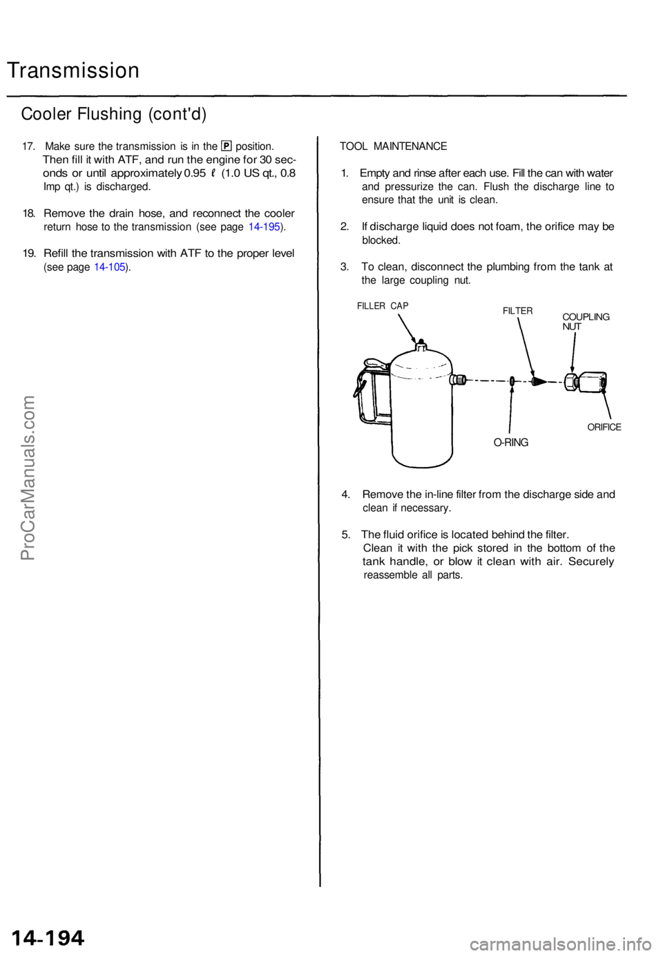
L MAINTENANC E
1. Empt y an d rins e afte r eac h use . Fil l th e ca n wit h wate r
and pressuriz e th e can . Flus h th e discharg e lin e t o
ensur e tha t th e uni t i s clean .
2. I f discharg e liqui d doe s no t foam , th e orific e ma y b e
blocked .
3. T o clean , disconnec t th e plumbin g fro m th e tan k a t
the larg e couplin g nut .
FILLE R CA PFILTE RCOUPLIN GNUT
ORIFIC E
O-RING
4. Remov e th e in-lin e filte r fro m th e discharg e sid e an d
clea n i f necessary .
5. Th e flui d orific e is locate d behin d th e filter .
Clea n i t wit h th e pic k store d i n th e botto m o f th e
tan k handle , o r blo w it clea n wit h air . Securel y
reassembl e al l parts .
ProCarManuals.com