Page 1110 of 1771

Differential Assembl y
Reassembl y (cont'd )
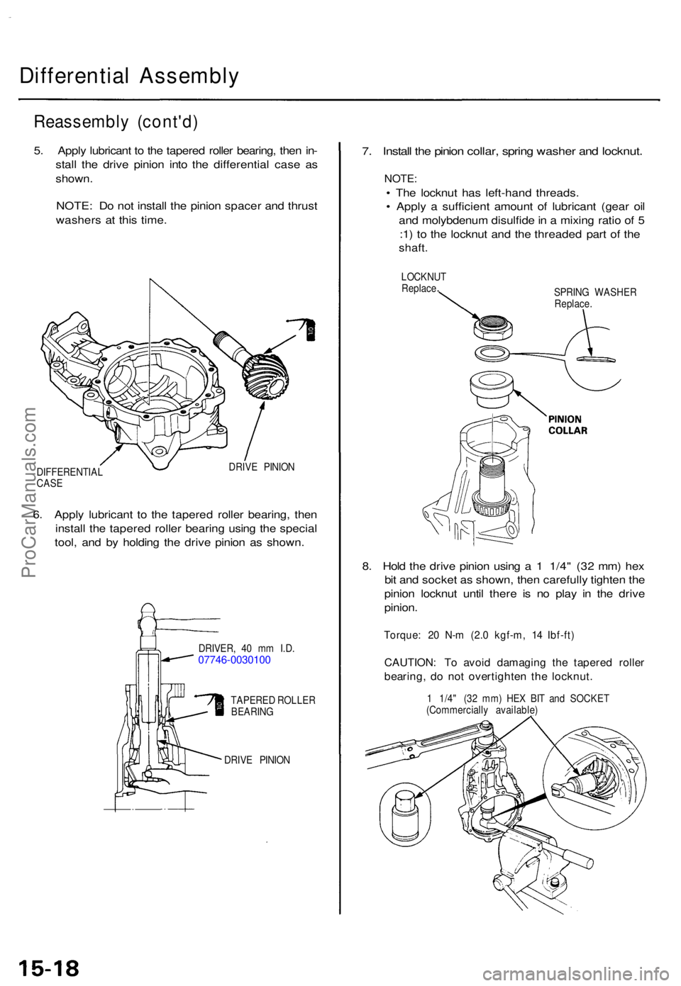
5. Appl y lubrican t t o th e tapere d rolle r bearing , the n in -
stal l th e driv e pinio n int o th e differentia l cas e a s
shown .
NOTE : D o no t instal l th e pinio n space r an d thrus t
washer s a t thi s time .
DIFFERENTIA L
CAS E DRIV
E PINIO N
6. Appl y lubrican t t o th e tapere d rolle r bearing , the n
instal l th e tapere d rolle r bearin g usin g th e specia l
tool , an d b y holdin g th e driv e pinio n a s shown .
DRIVER , 4 0 m m I.D .07746-0030100
TAPERE D ROLLE R
BEARIN G
DRIV E PINIO N
7. Instal l th e pinio n collar , sprin g washe r an d locknut .
NOTE:
• Th e locknu t ha s left-han d threads .
• Appl y a sufficien t amoun t o f lubrican t (gea r oi l
an d molybdenu m disulfid e in a mixin g rati o o f 5
: 1 ) t o th e locknu t an d th e threade d par t o f th e
shaft .
LOCKNU T
Replac e
SPRING WASHE R
Replace .
8. Hol d th e driv e pinio n usin g a 1 1/4 " (3 2 mm ) he x
bi t an d socke t a s shown , the n carefull y tighte n th e
pinio n locknu t unti l ther e i s n o pla y i n th e driv e
pinion .
Torque : 2 0 N- m (2. 0 kgf-m , 1 4 Ibf-ft )
CAUTION : T o avoi d damagin g th e tapere d rolle r
bearing , d o no t overtighte n th e locknut .
1 1/4 " (3 2 mm ) HE X BI T an d SOCKE T
(Commerciall y available )
ProCarManuals.com
Page 1112 of 1771
Differential Assembl y
Reassembl y (cont'd )
1 5 . Appl y lubrican t t o th e tapere d rolle r bearing , the n in -
stal l i t usin g th e specia l too l whil e holdin g th e driv e
pinio n a s shown .
DRIVER , 4 0 m m I.D .07746-0030100
TAPERE D ROLLE RBEARING
DRIVE PINIO N
16. Instal l a ne w oi l sea l usin g th e specia l tool s a s shown .
PINION COVE R
DRIVE R ATTACHMEN T
07LAD-PW50500
DRIVER07749-0010000
OIL SEA L
Replace .
17. Instal l th e pinio n collar , sprin g washe r an d locknut .
NOTE:
• Th e locknu t ha s left-han d threads .
• Appl y a sufficien t amoun t o f lubrican t (gea r oi l
an d molybdenu m disulfid e in a mixin g rati o o f 5
: 1 ) t o th e locknu t an d th e threade d par t o f th e
shaft .
LOCKNU T
Replace .
SPRING WASHE R
Replace .
18. Hol d th e driv e pinio n usin g a 1 1/4 " (3 2 mm ) he x
bi t an d socke t a s shown.
1 1/4 " (3 2 mm ) HE X BI T an d SOCKE T
(Commerciall y available )
ProCarManuals.com
Page 1113 of 1771

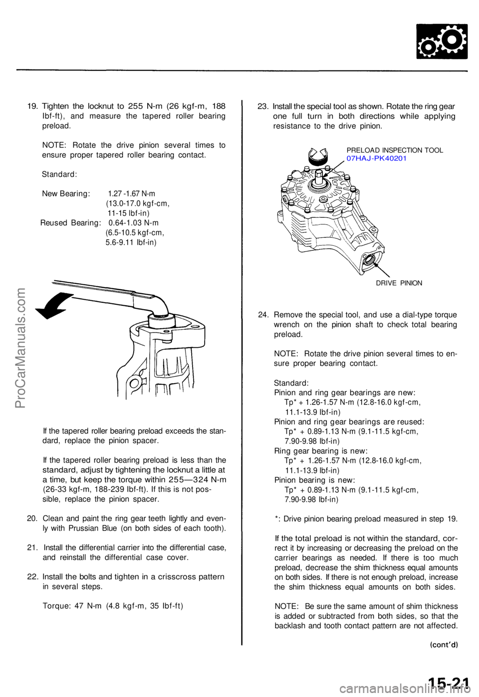
19. Tighte n th e locknu t t o 25 5 N- m (2 6 kgf-m , 18 8
Ibf-ft) , an d measur e th e tapere d rolle r bearin g
preload .
NOTE : Rotat e th e driv e pinio n severa l time s t o
ensur e prope r tapere d rolle r bearin g contact .
Standard :
New Bearing: 1.27 -1.67 N-m
(13.0-17.0 kgf-cm, 11-15 lbf-in)
Reuse d Bearing : 0.64-1.03 N-m
(6.5-10. 5 kgf-cm ,
5.6-9.1 1 Ibf-in )
If th e tapere d rolle r bearin g preloa d exceed s th e stan -
dard , replac e th e pinio n spacer .
I f th e tapere d rolle r bearin g preloa d i s les s tha n th e
standard , adjus t b y tightenin g th e locknu t a littl e a t
a time , bu t kee p th e torqu e withi n 255—32 4 N- m
(26-33 kgf-m, 188-239 Ibf-ft). If this is not pos-
sible , replac e th e pinio n spacer .
20 . Clea n an d pain t th e rin g gea r teet h lightl y an d even -
l y wit h Prussia n Blu e (o n bot h side s o f eac h tooth) .
21 . Instal l th e differentia l carrie r int o th e differentia l case ,
an d reinstal l th e differentia l cas e cover .
22. Instal l th e bolt s an d tighte n in a crisscros s patter n
in severa l steps.
Torque : 4 7 N- m (4. 8 kgf-m , 3 5 Ibf-ft )
23. Instal l th e specia l too l a s shown . Rotat e th e rin g gea r
one ful l tur n i n bot h direction s whil e applyin g
resistanc e t o th e driv e pinion .
PRELOA D INSPECTIO N TOO L07HAJ-PK40201
DRIVE PINIO N
24. Remov e th e specia l tool , an d us e a dial-typ e torqu e
wrenc h o n th e pinio n shaf t t o chec k tota l bearin g
preload .
NOTE: Rotat e th e driv e pinio n severa l time s t o en -
sur e prope r bearin g contact .
Standard :
Pinion an d rin g gea r bearing s ar e new :
Tp* + 1.26-1.57 N-m (12.8-16.0 kgf-cm,
11.1-13.9 Ibf-in)
Pinio n an d rin g gea r bearing s ar e reused :
Tp* + 0.89-1.1 3 N- m (9.1-11. 5 kgf-cm ,
7.90-9.9 8 Ibf-in )
Ring gea r bearin g is new :
Tp* + 1.26-1.5 7 N- m (12.8-16. 0 kgf-cm ,
11.1-13. 9 Ibf-in )
Pinion bearin g is new :
Tp* + 0.89-1.1 3 N- m (9.1-11. 5 kgf-cm ,
7.90-9.9 8 Ibf-in )
*: Driv e pinio n bearin g preloa d measure d in ste p 19 .
If th e tota l preloa d is no t withi n th e standard , cor -
rect i t b y increasin g o r decreasin g th e preloa d o n th e
carrie r bearing s a s needed . I f ther e i s to o muc h
preload , decreas e th e shi m thicknes s equa l amount s
o n bot h sides . I f ther e is no t enoug h preload , increas e
th e shi m thicknes s equa l amount s o n bot h sides .
NOTE : B e sur e th e sam e amoun t o f shi m thicknes s
i s adde d o r subtracte d fro m bot h sides , s o tha t th e
backlas h an d toot h contac t patter n ar e no t affected .
ProCarManuals.com
Page 1115 of 1771
32. Instal l th e differentia l cas e cover .
NOTE: Torqu e th e bolt s i n a crisscros s pattern , i n
severa l steps .
DIFFERENTIA L
CAS E COVE R10 x 1.2 5 m m47 N- m (4. 8 kgf-m , 3 5 Ibf-ft )
33. Instal l th e oi l sea l usin g th e specia l tool s a s shown .
DRIVER07749-001000 0
DRIVER ATTACHMEN T07947-6110501 o r
07947-611050 0
OIL SEA L
Replace .
PILOT,
28 x 30 m m07JAD-PH80400
34. Instal l th e O-rin g an d th e oi l cooler .
OIL COOLE R
O-RIN G
Replace .
8 x 1.2 5 mm27 N- m (2. 8 kgf-m , 2 0 Ibf-ft )
6 x 1. 0 m m12 N- m (1. 2 kgf-m ,8.7 Ibf-ft )
35. Stak e th e locknu t ta b int o th e groove .
1.0 m m (0.04 in)
3.5 m m (0.1 4 in)
ProCarManuals.com
Page 1124 of 1771
Driveshafts
Removal
1. Loose n th e whee l nut s slightly .
2. Rais e th e fron t o f vehicle , an d suppor t i t wit h safet y
stand s in th e prope r location s (se e sectio n 1 ).
3 . Remov e th e whee l nut s an d fron t wheels .
4 . Drai n th e differential oil (se e sectio n 15 ).
NOTE : I t i s no t necessar y t o drai n th e differential oil
whe n th e righ t driveshaf t i s removed .
5 . Rais e th e lockin g ta b o n th e spindl e nut , the n remov e
the nut .
FRON T WHEE L
WHEEL NU T
SPINDL E NU T
24 x 1. 5 m mReplace .
6. Remov e th e self-lockin g nu t an d flang e bolt .
7 . Remov e th e dampe r fork .
FLANG E BOL T10 x 1.2 5 mm43 N- m (4. 4 kgf-m , 3 2 Ibf-ft )
SELF-LOCKIN G NU T
12 x 1.2 5 m m64 N- m (6. 5 kgf-m , 4 7 Ibf-ft )Replace .
ProCarManuals.com
Page 1127 of 1771
Disassembly
1. Carefull y clam p th e driveshaf t i n a vis e wit h sof t
jaws , the n remov e th e se t rin g fro m th e inboar d
joint.
2. Remov e th e boo t band s o n th e inboar d join t an d
outboar d joint .
— If th e boo t ban d is a lockin g tab s type , pr y u p th e
lockin g tab s wit h a screwdrive r an d rais e th e en d
of th e band .
INBOAR D JOIN T
SET RIN GReplace .
— If th e boo t ban d i s th e welde d type , cu t i t of f a s
shown .
CAUTION : Tak e car e no t t o damag e th e boot .
BOOT BAN DReplace .
ProCarManuals.com
Page 1136 of 1771

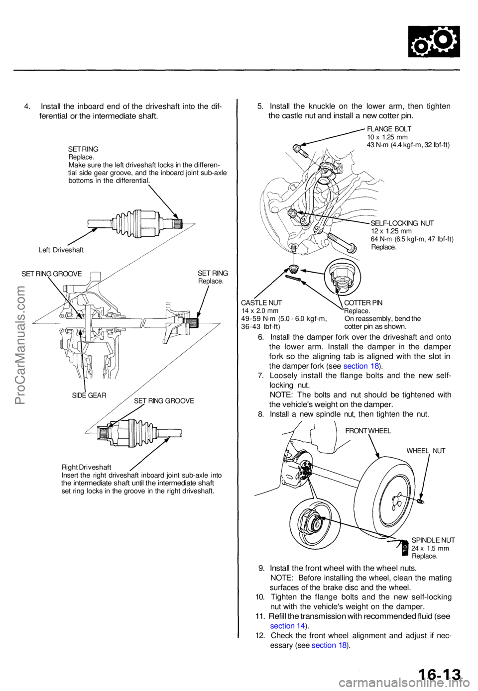
4. Instal l th e inboar d en d o f th e driveshaf t int o th e dif -
ferentia l o r th e intermediat e shaft .
SET RIN GReplace .Make sur e th e lef t driveshaf t lock s in th e differen -
tia l sid e gea r groove , an d th e inboar d join t sub-axl e
bottom s i n th e differential .
Lef t Driveshaf t
SE T RIN G GROOV E SE
T RIN G
Replace .
Right Driveshaf t
Inser t th e righ t driveshaf t inboar d join t sub-axl e int o
the intermediat e shaf t unti l th e intermediat e shaf tset rin g lock s in th e groov e in th e righ t driveshaft .
5. Instal l th e knuckl e o n th e lowe r arm , the n tighte n
the castl e nu t an d instal l a ne w cotte r pin .
FLANG E BOL T10 x 1.2 5 mm43 N- m (4. 4 kgf-m , 3 2 Ibf-ft )
SELF-LOCKIN G NU T
12 x 1.2 5 mm64 N- m (6. 5 kgf-m , 4 7 Ibf-ft )Replace .
CASTL E NU T
14 x 2. 0 m m49-5 9 N- m (5. 0 - 6. 0 kgf-m ,
36-4 3 Ibf-ft )
6. Instal l th e dampe r for k ove r th e driveshaf t an d ont o
th e lowe r arm . Instal l th e dampe r i n th e dampe r
fork s o th e alignin g ta b i s aligne d wit h th e slo t i n
th e dampe r for k (se e sectio n 18 ).
Loosel y instal l th e flang e bolt s an d th e ne w self -
lockin g nut .
NOTE : Th e bolt s an d nu t shoul d b e tightene d wit h
the vehicle' s weigh t o n th e damper .
Install a ne w spindl e nut , the n tighte n th e nut .
7.
8.
FRON T WHEE L
WHEE L NU T
SPINDL E NU T24 x 1. 5 m mReplace .
9. Instal l th e fron t whee l wit h th e whee l nuts .
NOTE : Befor e installin g th e wheel , clea n th e matin g
surface s o f th e brak e dis c an d th e wheel .
10 . Tighte n th e flang e bolt s an d th e ne w self-lockin g
nu t wit h th e vehicle' s weigh t o n th e damper .
11. Refil l th e transmissio n wit h recommende d flui d (se e
sectio n 14 ).
12 . Chec k th e fron t whee l alignmen t an d adjus t i f nec -
essar y (se e sectio n 18 ).
COTTE R PI N'Replace .On reassembly , ben d th ecotte r pi n a s shown .
SET RIN G GROOV ESIDE GEA R
ProCarManuals.com
Page 1143 of 1771

Special Tool s
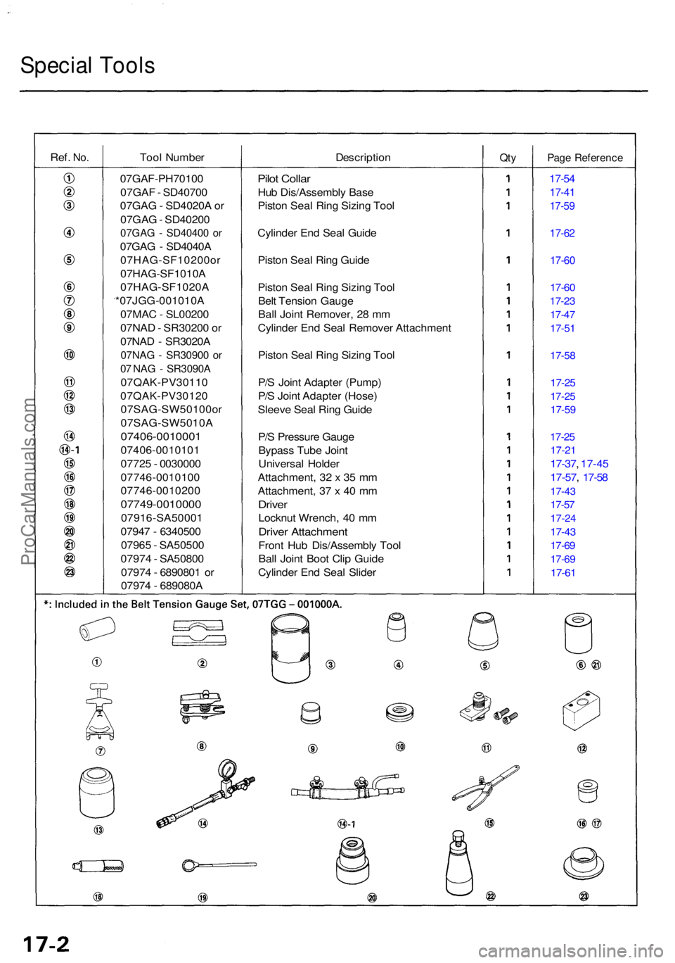
Ref. No.Too l Numbe r DescriptionQtyPag e Referenc e
Pilot Colla r
Hub Dis/Assembl y Bas e
Pisto n Sea l Rin g Sizin g Too l
Cylinde r En d Sea l Guid e
Pisto n Sea l Rin g Guid e
Pisto n Sea l Rin g Sizin g Too l
Bel t Tensio n Gaug e
Bal l Join t Remover , 2 8 m m
Cylinde r En d Sea l Remove r Attachmen t
Pisto n Sea l Rin g Sizin g Too l
P/ S Join t Adapte r (Pump )
P/ S Join t Adapte r (Hose )
Sleev e Sea l Rin g Guid e
P/ S Pressur e Gaug e
Bypas s Tub e Join t
Universa l Holde r
Attachment , 3 2 x 3 5 m m
Attachment , 3 7 x 4 0 m m
Drive r
Locknu t Wrench , 4 0 m m
Drive r Attachmen t
Front Hu b Dis/Assembl y Too l
Bal l Join t Boo t Cli p Guid e
Cylinde r En d Sea l Slide r
17-54
17-4 1
17-59
17-6 2
17-60
17-60
17-2 3
17-47
17-5 1
17-5 8
17-25
17-2 5
17-59
17-25
17-2 1
17-37 , 17-4 5
17-57 , 17-5 8
17-43
17-57
17-2 4
17-43
17-69
17-6 9
17-61
07GAF-PH7010 0
07GA F - SD4070 0
07GA G - SD4020 A o r
07GA G - SD4020 0
07GAG - SD4040 0 o r
07GA G - SD4040 A
07HAG-SF10200o r
07HAG-SF1010A
07HAG-SF1020 A
*07JGG-001010A
07MA C - SL0020 0
07NA D - SR3020 0 o r
07NA D - SR3020 A
07NAG - SR3090 0 o r
07 NA G - SR3090 A
07QAK-PV3011 0
07QAK-PV3012 0
07SAG-SW50100o r
07SAG-SW5010 A
07406-0010001
07406-001010 1
0772 5 - 003000 0
07746-001010 0
07746-001020 0
07749-0010000
07916-SA5000 1
0794 7 - 634050 0
0796 5 - SA5050 0
0797 4 - SA5080 0
0797 4 - 689080 1 o r
0797 4 - 689080 A
ProCarManuals.com