1995 ACURA TL lock
[x] Cancel search: lockPage 1213 of 1771
Steering Gearbo x
Installatio n (cont'd )
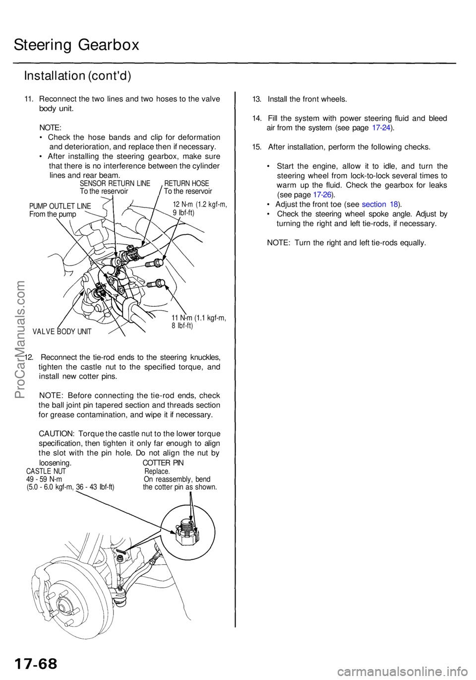
11. Reconnec t th e tw o line s an d tw o hose s t o th e valv e
body unit .
NOTE :
• Chec k th e hos e band s an d cli p fo r deformatio n
an d deterioration , an d replac e the n if necessary .
• Afte r installin g th e steerin g gearbox , mak e sur e
tha t ther e is n o interferenc e betwee n th e cylinde r
line s an d rea r beam .
PUMP OUTLE T LIN EFrom th e pum p
12 N- m (1. 2 kgf-m ,9 Ibf-ft )
VALV E BOD Y UNI T
11 N- m (1. 1 kgf-m ,8 Ibf-ft )
12. Reconnec t th e tie-ro d end s t o th e steerin g knuckles ,
tighte n th e castl e nu t t o th e specifie d torque , an d
instal l ne w cotte r pins .
NOTE : Befor e connectin g th e tie-ro d ends , chec k
th e bal l join t pi n tapere d sectio n an d thread s sectio n
fo r greas e contamination , an d wip e it i f necessary .
CAUTION : Torqu e th e castl e nu t t o th e lowe r torqu e
specification , the n tighte n it onl y fa r enoug h t o alig n
th e slo t wit h th e pi n hole . D o no t alig n th e nu t b y
loosening . COTTER PI NCASTL E NU T Replace.49 - 5 9 N- m O n reassembly , ben d(5.0 - 6. 0 kgf-m , 3 6 - 4 3 Ibf-ft ) th e cotte r pi n a s shown .
13. Instal l th e fron t wheels .
14 . Fil l th e syste m wit h powe r steerin g flui d an d blee d
ai r fro m th e syste m (se e pag e 17-24 ).
15 . Afte r installation , perfor m th e followin g checks .
• Star t th e engine , allo w i t t o idle , an d tur n th e
steerin g whee l fro m lock-to-loc k severa l time s t o
war m u p th e fluid . Chec k th e gearbo x fo r leak s
(se e pag e 17-26 ).
• Adjus t th e fron t to e (se e sectio n 18 ).
• Chec k th e steerin g whee l spok e angle . Adjus t b y
turnin g th e righ t an d lef t tie-rods , i f necessary .
NOTE : Tur n th e righ t an d lef t tie-rod s equally .
SENSO R RETUR N LIN ETo th e reservoi rRETURN HOS ETo th e reservoi r
ProCarManuals.com
Page 1218 of 1771
Wheel Alignmen t
Caster
NOTE : Fo r prope r inspection/adjustmen t o f th e whee l
alignment , chec k an d adjus t th e followin g befor e check -
ing th e alignment .
• Chec k tha t th e suspensio n i s no t modified .
• Chec k th e tir e siz e an d tir e pressure .
• Chec k th e runou t o f th e wheel s an d tires .
• Chec k th e suspensio n bal l joints . (Hol d th e whee l wit h
you r hands , the n mov e i t u p an d down , an d righ t an d
lef t t o chec k fo r wobbling. )
Inspection
NOTE: Us e commercially-availabl e computerize d fou r
whee l alignmen t equipmen t t o measur e whee l align -
men t (caster , camber , toe , and/o r turnin g angle) .
Follo w th e equipmen t manufacturer' s instructions .
1 . Chec k th e caste r angle .
Caste r angle : 2°07 ' ± 1 °
2 . I f ou t o f specification , recor d th e caste r reading , the n
adjus t th e caster .
Adjustmen t
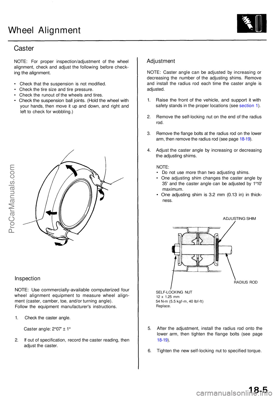
NOTE: Caste r angl e ca n b e adjuste d b y increasin g o r
decreasin g th e numbe r o f th e adjustin g shims . Remov e
an d instal l th e radiu s ro d eac h tim e th e caste r angl e i s
adjusted .
1. Rais e th e fron t o f th e vehicle , an d suppor t i t wit h
safet y stand s in th e prope r location s (se e sectio n 1 ).
2 . Remov e th e self-lockin g nu t o n th e en d o f th e radiu s
rod.
3. Remov e th e flang e bolt s a t th e radiu s ro d o n th e lowe r
arm , the n remov e th e radiu s ro d (se e pag e 18-19 ).
4 . Adjus t th e caste r angl e b y increasin g o r decreasin g
the adjustin g shims .
NOTE:
• D o no t us e mor e tha n tw o adjustin g shims .
• On e adjustin g shi m change s th e caste r angl e b y
35 ' an d th e caste r angl e ca n b e adjuste d b y 1°10 '
maximum .
• On e adjustin g shi m is 3. 2 m m (0.1 3 in ) i n thick -
ness.
ADJUSTIN G SHI M
RADIU S RO D
SELF-LOCKIN G NU T
12 x 1.2 5 mm54 N- m (5. 5 kgf-m , 4 0 Ibf-ft )Replace .
5. Afte r th e adjustment , instal l th e radiu s ro d ont o th e
lowe r arm , the n tighte n th e flang e bolt s (se e pag e
18-19 ).
6 . Tighte n th e ne w self-lockin g nu t t o specifie d torque .
ProCarManuals.com
Page 1219 of 1771
Wheel Alignmen t
Camber
Inspectio n
NOTE: Us e commercially-availabl e computerize d fou r
whee l alignmen t equipmen t t o measur e whee l align -
men t (caster , camber , toe , and/o r turnin g angle) .
Follo w th e equipmen t manufacturer' s instructions .
1 . Chec k th e cambe r angle .
Cambe r angle :
Front: 0°00'±1 °
Rear : -0°30'±1 °
2 . I f ou t o f specification , chec k fo r ben t o r damage d sus -
pensio n components .
Front To e Inspection/Adjustmen t
NOTE: Us e commercially-availabl e computerize d fou r
whee l alignmen t equipmen t t o measur e whee l align -
men t (caster , camber , toe , and/o r turnin g angle) .
Follo w th e equipmen t manufacturer' s instructions .
1. Check the tire pressure.
2. Cente r steerin g whee l spokes .
3 . Chec k th e to e wit h th e wheel s pointe d straigh t
ahead.
Front toe : OU T 1. 0 ± 2 m m (1/1 6 ± 1/1 6 in )
— If adjustmen t i s required , g o o n to ste p 4 .
— If n o adjustmen t i s required , remov e alignmen t
equipment .
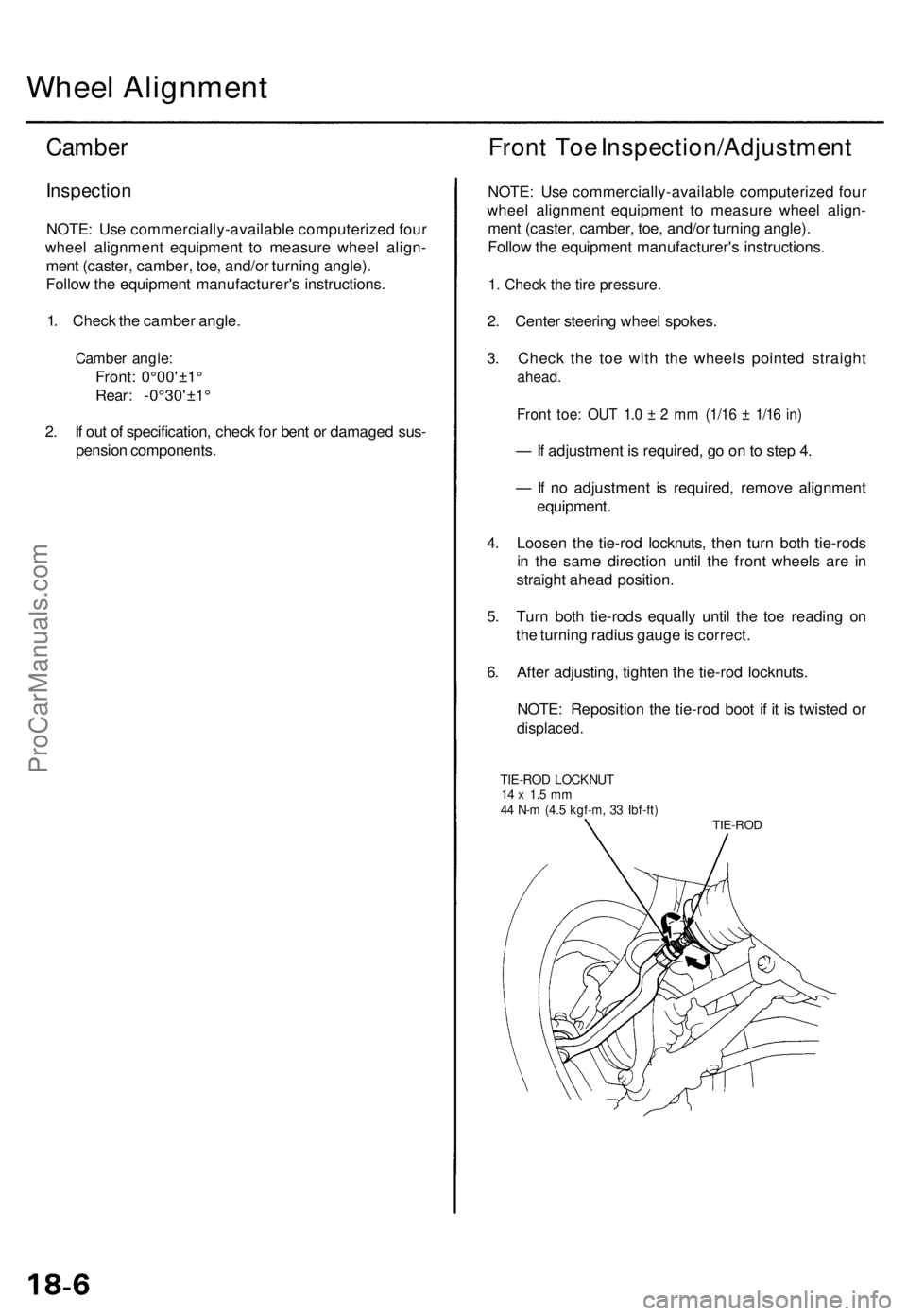
4 . Loose n th e tie-ro d locknuts , the n tur n bot h tie-rod s
i n th e sam e directio n unti l th e fron t wheel s ar e i n
straigh t ahea d position .
5 . Tur n bot h tie-rod s equall y unti l th e to e readin g o n
th e turnin g radiu s gaug e is correct .
6 . Afte r adjusting , tighte n th e tie-ro d locknuts .
NOTE : Repositio n th e tie-ro d boo t i f i t i s twiste d o r
displaced .
TIE-ROD LOCKNU T14 x 1. 5 m m44 N- m (4. 5 kgf-m , 3 3 Ibf-ft )TIE-RO D
ProCarManuals.com
Page 1220 of 1771
Rear To e Inspection/Adjustmen t
NOTE: Us e commercially-availabl e computerize d fou r
whee l alignmen t equipmen t t o measur e whee l align -
men t (caster , camber , to e and/o r turnin g angle) . Follo w
th e equipmen t manufacturer' s instructions .
1. Releas e parkin g brake .
NOTE:
• Measur e differenc e i n to e measurement s wit h
th e wheel s pointe d straigh t ahead .
• I f th e parkin g brak e is engaged , yo u ma y ge t a n
incorrec t reading .
Rea r toe-in : 2 ± 2 mm (1/1 6 ± 1/1 6 in )
— If adjustmen t i s required , g o to ste p 2 .
— If n o adjustmen t i s required , remov e alignmen t
equipment .
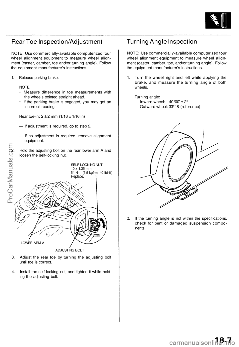
2 . Hol d th e adjustin g bol t o n th e rea r lowe r ar m A an d
loose n th e self-lockin g nut .
SELF-LOCKIN G NU T10 x 1.2 5 mm54 N- m (5. 5 kgf-m , 4 0 Ibf-ft )Replace .
LOWER AR M A
ADJUSTIN G BOL T
3. Adjus t th e rea r to e b y turnin g th e adjustin g bol t
unti l to e is correct .
4 . Instal l th e self-lockin g nut , an d tighte n i t whil e hold -
in g th e adjustin g bolt .
Turnin g Angl e Inspectio n
NOTE: Us e commercially-availabl e computerize d fou r
whee l alignmen t equipmen t t o measur e whee l align -
men t (caster , camber , toe , and/o r turnin g angle) . Follo w
th e equipmen t manufacturer' s instructions .
1.Tur n th e whee l righ t an d lef t whil e applyin g th e
brake , an d measur e th e turnin g angl e o f bot h
wheels .
Turning angle :
Inward wheel : 40°00 ' ± 2°
Outwar d wheel : 33 ° 18 ' (reference )
2.If th e turnin g angl e i s no t withi n th e specifications ,
chec k fo r ben t o r damage d suspensio n compo -
nents .
ProCarManuals.com
Page 1222 of 1771
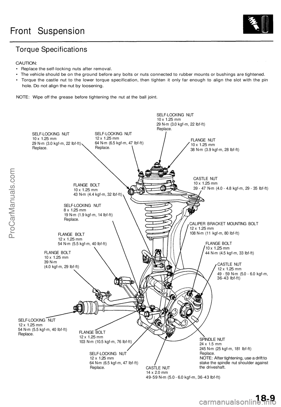
Front Suspension
Torque Specifications
CAUTION:
• Replace the self-locking nuts after removal.
• The vehicle should be on the ground before any bolts or nuts connected to rubber mounts or bushings are tightened.
• Torque the castle nut to the lower torque specification, then tighten it only far enough to align the slot with the pin
hole. Do not align the nut by loosening.
NOTE: Wipe off the grease before tightening the nut at the ball joint.
SELF-LOCKING NUT
10 x
1.25
mm
29 N-m (3.0 kgf-m, 22 Ibf-ft)
Replace.
SELF-LOCKING NUT
12 x
1.25
mm
64 N-m (6.5 kgf-m, 47 Ibf-ft)
Replace.
SELF-LOCKING NUT
10 x
1.25
mm
29 N-m (3.0 kgf-m, 22 Ibf-ft)
Replace.
FLANGE BOLT
10 x
1.25
mm
43 N-m (4.4 kgf-m, 32 Ibf-ft)
SELF-LOCKING NUT
8 x
1.25
mm
19 N-m (1.9 kgf-m, 14 Ibf-ft)
Replace.
FLANGE BOLT
12 x
1.25
mm
54 N-m (5.5 kgf-m, 40 Ibf-ft)
FLANGE BOLT
10 x
1.25
mm
39 N-m
(4.0 kgf-m, 29 Ibf-ft)
SELF-LOCKING NUT
12 x
1.25
mm
54 N-m (5.5 kgf-m, 40 Ibf-ft)
Replace.
FLANGE NUT
10 x
1.25
mm
38 N-m (3.9 kgf-m, 28 Ibf-ft)
CASTLE NUT
10 x
1.25
mm
39 - 47 N-m (4.0 - 4.8 kgf-m, 29 - 35 Ibf-ft)
CALIPER BRACKET MOUNTING BOLT
12 x
1.25
mm
108 N-m (11 kgf-m, 80 Ibf-ft)
FLANGE BOLT
10 x
1.25
mm
44 N-m (4.5 kgf-m, 33 Ibf-ft)
CASTLE NUT
12 x
1.25
mm
49 - 59 N-m (5.0 - 6.0 kgf-m,
36-43 Ibf-ft)
FLANGE BOLT
12 x
1.25
mm
103 N-m (10.5 kgf-m, 76 Ibf-ft)
SELF-LOCKING NUT
12 x
1.25
mm
64 N-m (6.5 kgf-m, 47 Ibf-ft)
Replace.
CASTLE NUT
14 x 2.0 mm
49-59 N-m (5.0 - 6.0 kgf-m, 36-43 Ibf-ft)
SPINDLE NUT
24 x 1.5 mm
245 N-m (25 kgf-m, 181 Ibf-ft)
Replace.
NOTE: After tightening, use a drift to
stake the spindle nut shoulder against
the driveshaft.ProCarManuals.com
Page 1224 of 1771
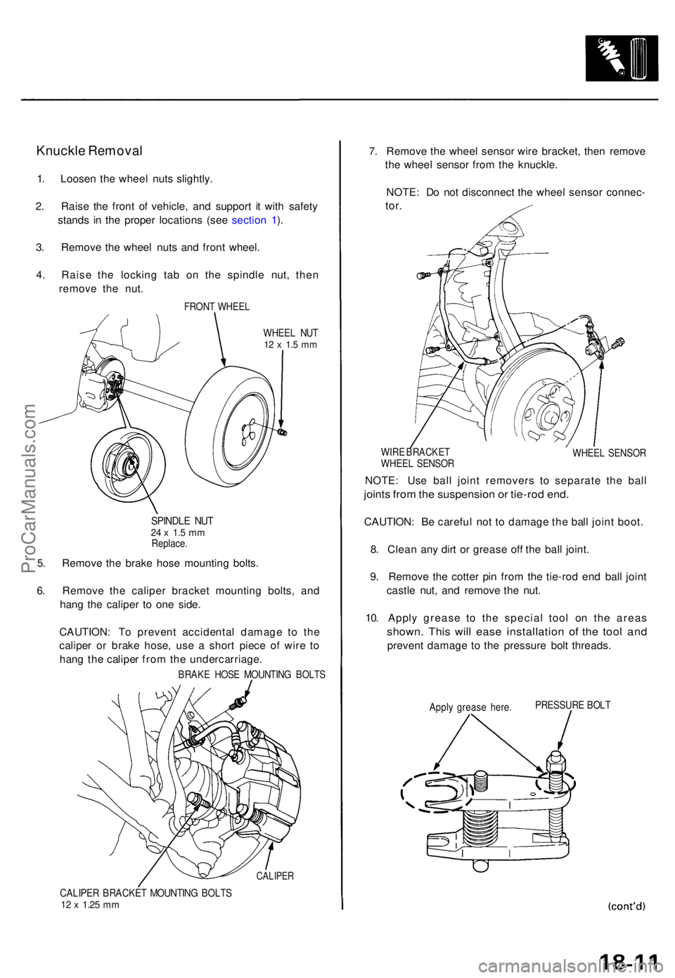
Knuckle Remova l
1. Loose n th e whee l nuts slightly .
2 . Rais e th e fron t o f vehicle , an d suppor t i t wit h safet y
stand s i n th e prope r location s (se e sectio n 1 ).
3 . Remov e th e whee l nuts and fron t wheel .
4 . Rais e th e lockin g ta b o n th e spindl e nut , the n
remov e th e nut .
FRON T WHEE L
WHEE L NU T
12 x 1. 5 m m
SPINDL E NU T24 x 1. 5 m mReplace .
5. Remov e th e brak e hos e mountin g bolts .
6 . Remov e th e calipe r bracke t mountin g bolts , an d
han g th e calipe r t o on e side .
CAUTION : T o preven t accidenta l damag e t o th e
calipe r o r brak e hose , us e a shor t piec e o f wir e t o
han g th e calipe r fro m th e undercarriage .
BRAKE HOS E MOUNTIN G BOLT S
CALIPE R
CALIPER BRACKE T MOUNTIN G BOLT S12 x 1.2 5 mm
7. Remov e th e whee l senso r wir e bracket , the n remov e
th e whee l senso r fro m th e knuckle .
NOTE : D o no t disconnec t th e whee l senso r connec -
tor.
WIR E BRACKE T
WHEE L SENSO R WHEE
L SENSO R
NOTE: Us e bal l join t remover s t o separat e th e bal l
joints fro m th e suspensio n o r tie-ro d end .
CAUTION : B e carefu l no t t o damag e th e bal l join t boot .
8 . Clea n an y dir t o r greas e of f th e bal l joint .
9 . Remov e th e cotte r pi n fro m th e tie-ro d en d bal l join t
castl e nut , an d remov e th e nut .
10 . Appl y greas e t o th e specia l too l o n th e area s
shown . Thi s wil l eas e installatio n of the too l an d
preven t damag e t o th e pressur e bol t threads .
Apply greas e here . PRESSUR
E BOL T
ProCarManuals.com
Page 1227 of 1771
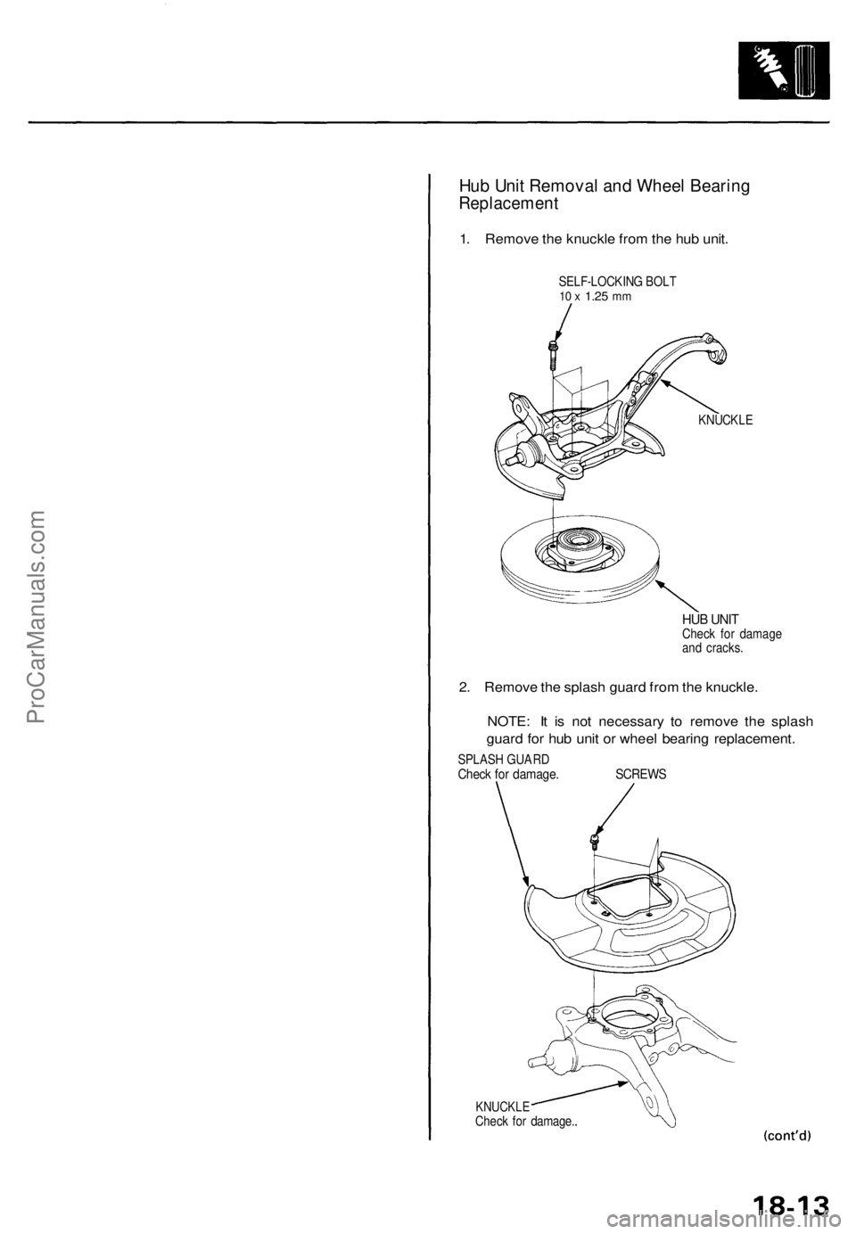
Hub Unit Removal and Wheel Bearing
Replacement
1. Remove the knuckle from the hub unit.
SELF-LOCKING BOLT
10 x
1.25
mm
KNUCKLE
HUB UNIT
Check for damage
and cracks.
2. Remove the splash guard from the knuckle.
NOTE: It is not necessary to remove the splash
guard for hub unit or wheel bearing replacement.
SPLASH GUARD
Check for damage. SCREWS
KNUCKLE
Check for damage.ProCarManuals.com
Page 1231 of 1771
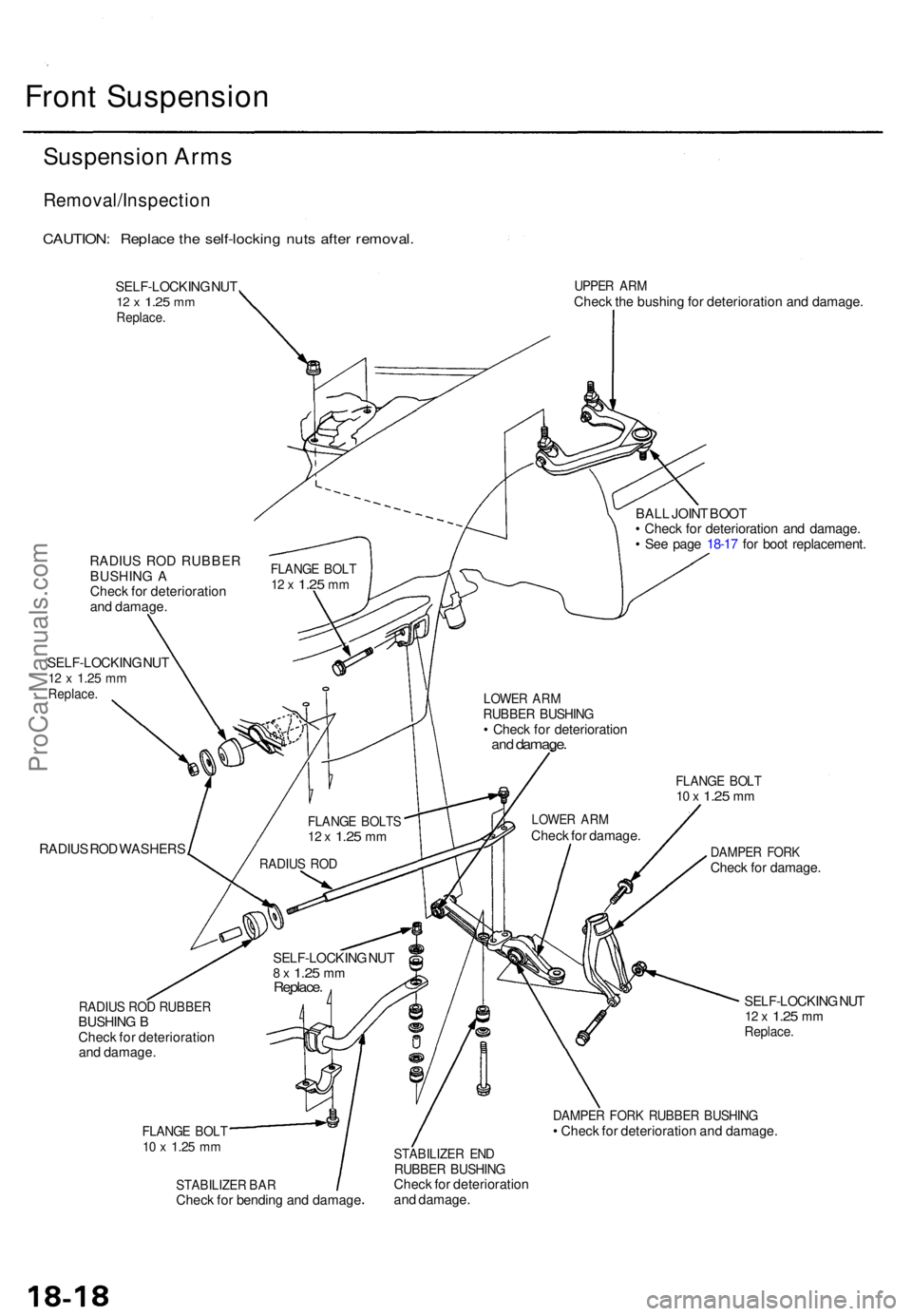
Front Suspensio n
Suspension Arm s
Removal/Inspectio n
CAUTION: Replac e th e self-lockin g nut s afte r removal .
SELF-LOCKIN G NU T12 x 1.2 5 mmReplace .
UPPER AR MChec k th e bushin g fo r deterioratio n an d damage .
RADIU S RO D RUBBE R
BUSHIN G A
Chec k fo r deterioratio n
an d damage .
SELF-LOCKIN G NU T
12 x 1.2 5 mmReplace .
RADIUS RO D WASHER S BAL
L JOIN T BOO T
• Chec k fo r deterioratio n an d damage .
• Se e pag e 18-1 7 fo r boo t replacement .
FLANGE BOL T10 x 1.2 5 mm
DAMPE R FOR KCheck fo r damage .
RADIUS RO D RUBBE RBUSHING B
Chec k fo r deterioratio n
an d damage .
FLANGE BOL T10 x 1.2 5 mm
SELF-LOCKIN G NU T12 x 1.2 5 mmReplace .
DAMPER FOR K RUBBE R BUSHIN G• Chec k fo r deterioratio n an d damage .
STABILIZE R BA RChec k fo r bendin g an d damag e
STABILIZE R EN DRUBBE R BUSHIN GCheck fo r deterioratio n
an d damage .
SELF-LOCKIN
G NU T
8 x 1.2 5 mmReplace .
RADIUS RO D
FLANG E BOLT S12 x 1.2 5 mm
LOWE R AR MChec k fo r damage .
LOWER AR MRUBBE R BUSHIN G• Chec k fo r deterioratio nand damage .
FLANGE BOL T12 x 1.2 5 mm
ProCarManuals.com