1995 ACURA TL lock
[x] Cancel search: lockPage 1242 of 1771
Installation
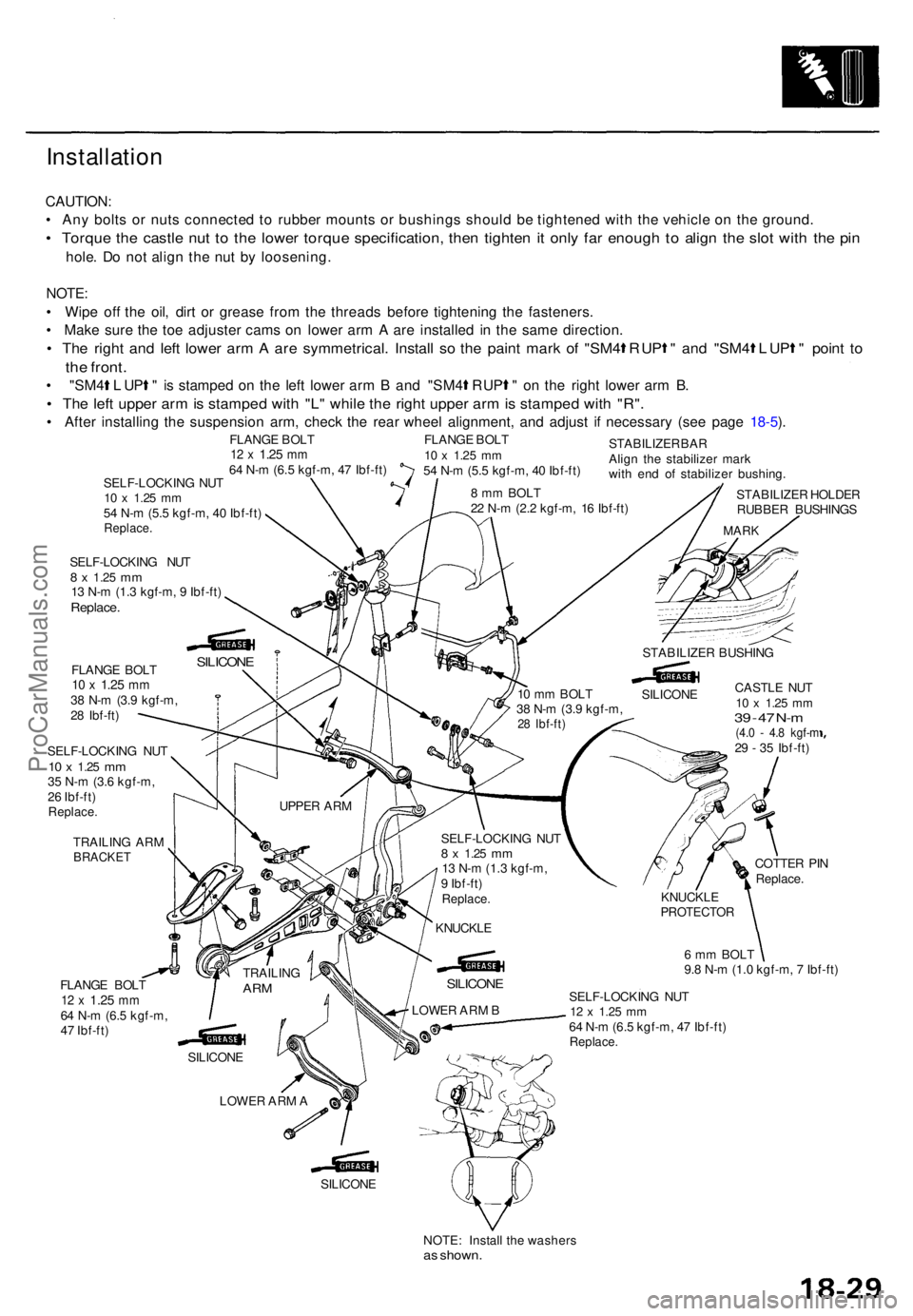
CAUTION:
• An y bolt s o r nut s connecte d t o rubbe r mount s o r bushing s shoul d b e tightene d wit h th e vehicl e o n th e ground .
• Torqu e th e castl e nu t t o th e lowe r torqu e specification , the n tighte n it onl y fa r enoug h t o alig n th e slo t wit h th e pi n
hole . D o no t alig n th e nu t b y loosening .
NOTE :
• Wip e of f th e oil , dir t o r greas e fro m th e thread s befor e tightenin g th e fasteners .
• Mak e sur e th e to e adjuste r cam s o n lowe r ar m A ar e installe d i n th e sam e direction .
• Th e righ t an d lef t lowe r ar m A ar e symmetrical . Instal l s o th e pain t mar k o f "SM 4 R UP " an d "SM 4 L UP " poin t t o
th e front .
• "SM 4 L UP " is stampe d o n th e lef t lowe r ar m B an d "SM 4 R UP " on th e righ t lowe r ar m B .
• Th e lef t uppe r ar m is stampe d wit h "L " whil e th e righ t uppe r ar m is stampe d wit h "R" .
• Afte r installin g th e suspensio n arm , chec k th e rea r whee l alignment , an d adjus t i f necessar y (se e pag e 18-5 ).
SELF-LOCKIN G NU T10 x 1.2 5 mm54 N- m (5. 5 kgf-m , 4 0 Ibf-ft )Replace .
SELF-LOCKIN G NU T8 x 1.2 5 mm13 N- m (1. 3 kgf-m , 9 Ibf-ft )Replace .
FLANGE BOL T10 x 1.2 5 mm38 N- m (3. 9 kgf-m ,
2 8 Ibf-ft )
SELF-LOCKIN G NU T
10 x 1.2 5 mm35 N- m (3. 6 kgf-m ,
2 6 Ibf-ft )
Replace .
TRAILIN G AR MBRACKE T
STABILIZE R HOLDE R
RUBBE R BUSHING S
MARK
CASTL E NU T10 x 1.2 5 mm39 - 4 7 N- m(4. 0 - 4. 8 kgf- m29 - 3 5 Ibf-ft )
FLANG E BOL T
12 x 1.2 5 mm64 N- m (6. 5 kgf-m ,
4 7 Ibf-ft ) COTTE
R PI N
Replace .
6 m m BOL T
9. 8 N- m (1. 0 kgf-m , 7 Ibf-ft )
SILICON E
NOTE: Instal l th e washer s
as shown .
8 m m BOL T
2 2 N- m (2. 2 kgf-m , 1 6 Ibf-ft )
FLANG
E BOL T
12 x 1.2 5 mm64 N- m (6. 5 kgf-m , 4 7 Ibf-ft )
SILICON E
UPPER AR M
TRAILIN G
ARM
SILICON E
LOWE R AR M A SELF-LOCKIN
G NU T
12 x 1.2 5 mm64 N- m (6. 5 kgf-m , 4 7 Ibf-ft )Replace .
KNUCKL EPROTECTO R
LOWER AR M B
SILICON E
KNUCKL E
SELF-LOCKIN
G NU T
8 x 1.2 5 mm13 N- m (1. 3 kgf-m ,
9 Ibf-ft )
Replace .
10 m m BOL T
3 8 N- m (3. 9 kgf-m ,
28 Ibf-ft )
SILICON E
STABILIZE
R BUSHIN G
STABILIZE
R BA R
Alig n th e stabilize r mar k
wit h en d o f stabilize r bushing .
FLANG
E BOL T
10 x 1.2 5 mm54 N- m (5. 5 kgf-m , 4 0 Ibf-ft )
ProCarManuals.com
Page 1244 of 1771
Disassembly/Inspection
Disassembly
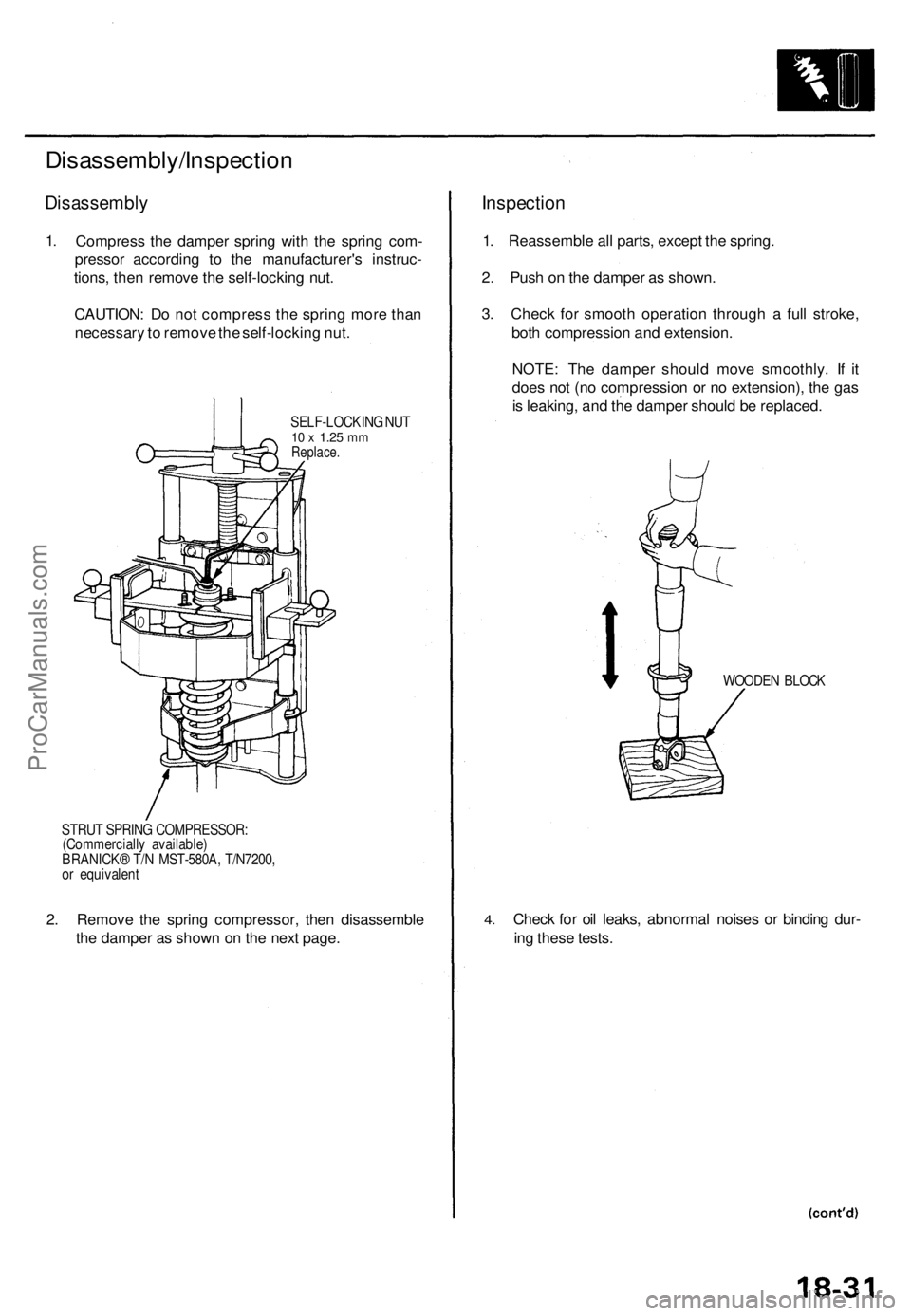
1. Compres s th e dampe r sprin g wit h th e sprin g com -
presso r accordin g t o th e manufacturer' s instruc -
tions , the n remov e th e self-lockin g nut .
CAUTION : D o no t compres s th e sprin g mor e tha n
necessar y to remov e th e self-lockin g nut .
SELF-LOCKIN G NU T10 x 1.2 5 mmReplace .
STRUT SPRIN G COMPRESSOR :
(Commerciall y available )
BRANICK ® T/ N MST-580A , T/N7200 ,
o r equivalen t
2. Remov e th e sprin g compressor , the n disassembl e
th e dampe r a s show n o n th e nex t page .
Inspectio n
1. Reassembl e al l parts , excep t th e spring .
2 . Pus h o n th e dampe r a s shown .
3 . Chec k fo r smoot h operatio n throug h a ful l stroke ,
bot h compressio n an d extension .
NOTE : Th e dampe r shoul d mov e smoothly . I f i t
doe s no t (n o compressio n o r n o extension) , th e ga s
i s leaking , an d th e dampe r shoul d b e replaced .
WOODEN BLOC K
4.Chec k fo r oi l leaks , abnorma l noise s o r bindin g dur -
in g thes e tests .
ProCarManuals.com
Page 1245 of 1771
Rear Damper
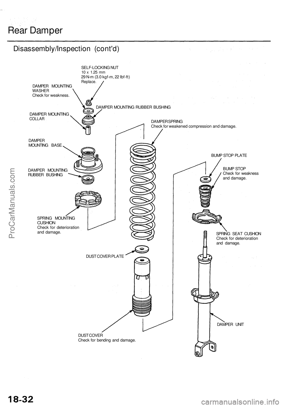
Disassembly/Inspection (cont'd)
DAMPER MOUNTING
WASHER
Check for weakness.
DAMPER MOUNTING
COLLAR
DAMPER
MOUNTING BASE
DAMPER MOUNTING
RUBBER BUSHING
SELF-LOCKING NUT
10 x
1.25
mm
29 N-m (3.0 kgf-m, 22 Ibf-ft)
Replace.
DAMPER MOUNTING RUBBER BUSHING
SPRING MOUNTING
CUSHION
Check for deterioration
and damage.
DAMPER SPRING
Check for weakened compression and damage.
DUST COVER
Check for bending and damage.
BUMP STOP PLATE
BUMP STOP
Check for weakness
and damage.
SPRING SEAT CUSHION
Check for deterioration
and damage.
DAMPER UNIT
DUST COVER PLATEProCarManuals.com
Page 1246 of 1771
Reassembly
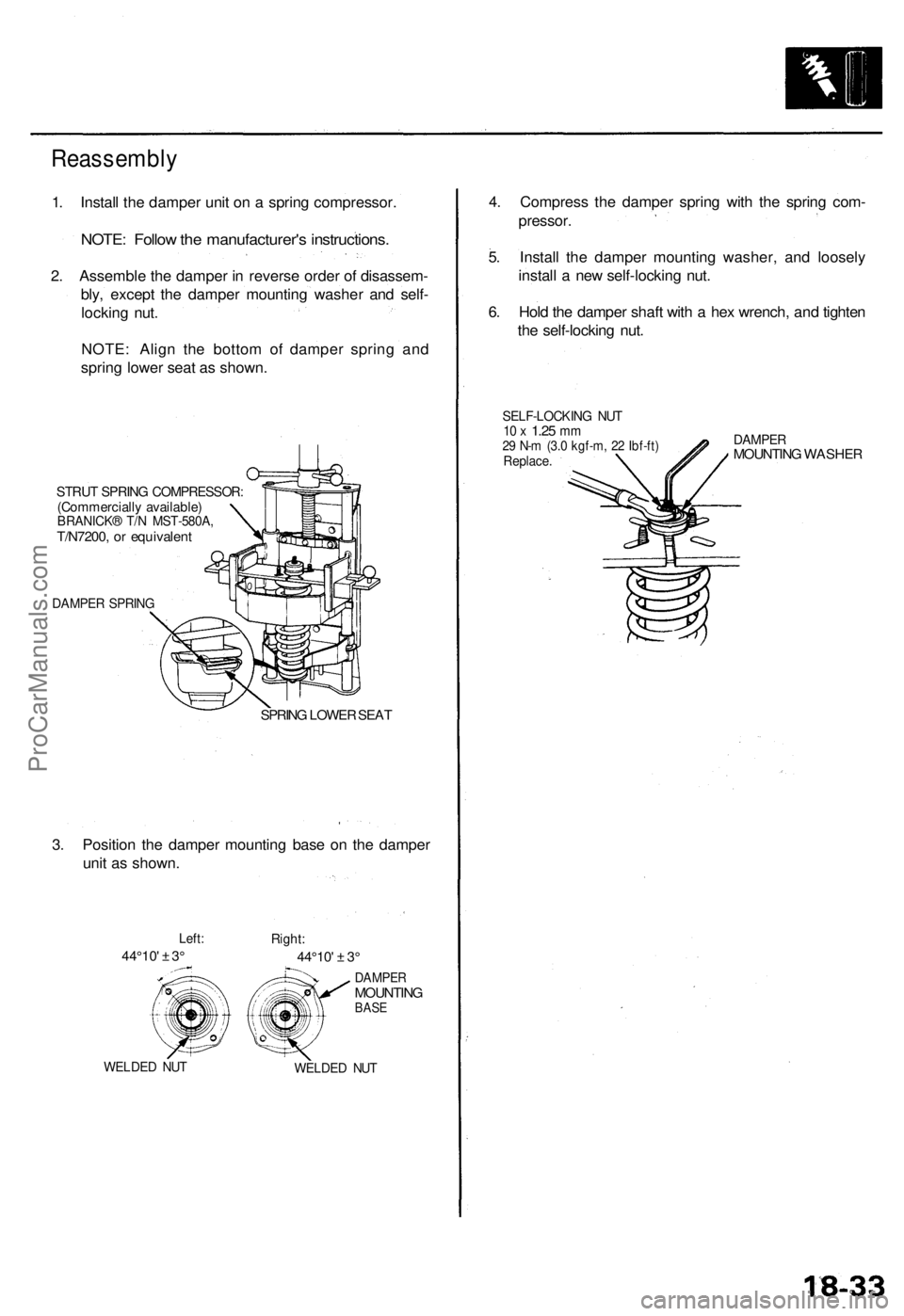
1. Install the damper unit on a spring compressor.
NOTE: Follow the manufacturer's instructions.
2. Assemble the damper in reverse order of disassem-
bly, except the damper mounting washer and self-
locking nut.
NOTE: Align the bottom of damper spring and
spring lower seat as shown.
STRUT SPRING COMPRESSOR:
(Commercially available)
BRANICK® T/N MST-580A,
T/N7200, or equivalent
DAMPER SPRING
SPRING LOWER SEAT
3. Position the damper mounting base on the damper
unit as shown.
Left:
44°10' ± 3°
Right:
44°10' ± 3°
WELDED NUT
DAMPER
MOUNTING
BASE
WELDED NUT
4. Compress the damper spring with the spring com-
pressor.
5. Install the damper mounting washer, and loosely
install a new self-locking nut.
6. Hold the damper shaft with a hex wrench, and tighten
the self-locking nut.
SELF-LOCKING NUT
10 x
1.25
mm
29 N-m (3.0 kgf-m, 22 Ibf-ft)
Replace.
DAMPER
MOUNTING WASHERProCarManuals.com
Page 1251 of 1771
Inspection and Adjustment
Brake Peda l
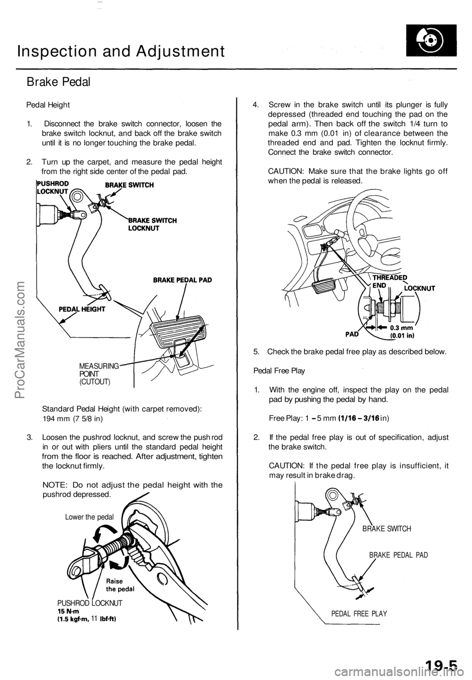
Pedal Heigh t
1 . Disconnec t th e brak e switc h connector , loose n th e
brak e switc h
locknut , and bac k of f th e brak e switc h
unti l i t i s n o longe r touchin g th e brak e pedal .
2 . Tur n u p th e carpet , an d measur e th e peda l heigh t
fro m th e righ t sid e cente r o f th e peda l pad .
MEASURIN GPOINT(CUTOUT )
Standard Peda l Heigh t (wit h carpe t removed) :
194 m m (7 5/ 8 in )
3. Loose n th e pushro d locknut , an d scre w th e pus h rod
i n o r ou t wit h plier s unti l th e standar d peda l heigh t
from th e floo r i s reached . Afte r adjustment , tighte n
the locknu t firmly .
NOTE : D o no t adjus t th e peda l heigh t wit h th e
pushro d depressed .
Lower th e peda l
PUSHRO D LOCKNU T15N-m(1.5kgf-m , 11 Ibf-ft )
4. Scre w in th e brak e switc h unti l it s plunge r i s full y
depresse d (threade d en d touchin g th e pa d o n th e
peda l arm) . The n bac k of f th e switc h 1/ 4 tur n t o
mak e 0. 3 m m (0.0 1 in ) of clearanc e betwee n th e
threade d en d an d pad . Tighte n th e locknu t firmly .
Connec t th e brak e switc h connector .
CAUTION : Mak e sur e tha t th e brak e light s g o of f
whe n th e peda l i s released .
5 . Chec k th e brak e peda l fre e pla y a s describe d below .
Peda l Fre e Pla y
1 . Wit h th e engin e off , inspec t th e pla y o n th e peda l
pad b y pushin g th e peda l b y hand .
Free Play : 1 - 5 m m (1/16-3/1 6 in)
2 . I f th e peda l fre e pla y i s ou t o f specification , adjus t
th e brak e switch .
CAUTION : I f th e peda l fre e pla y i s insufficient , i t
ma y resul t i n brak e drag .
BRAK E SWITC H
BRAKE PEDA L PA D
PEDA L FRE E PLA Y
ProCarManuals.com
Page 1252 of 1771
Inspection an d Adjustmen t
Parking Brak e
Inspectio n
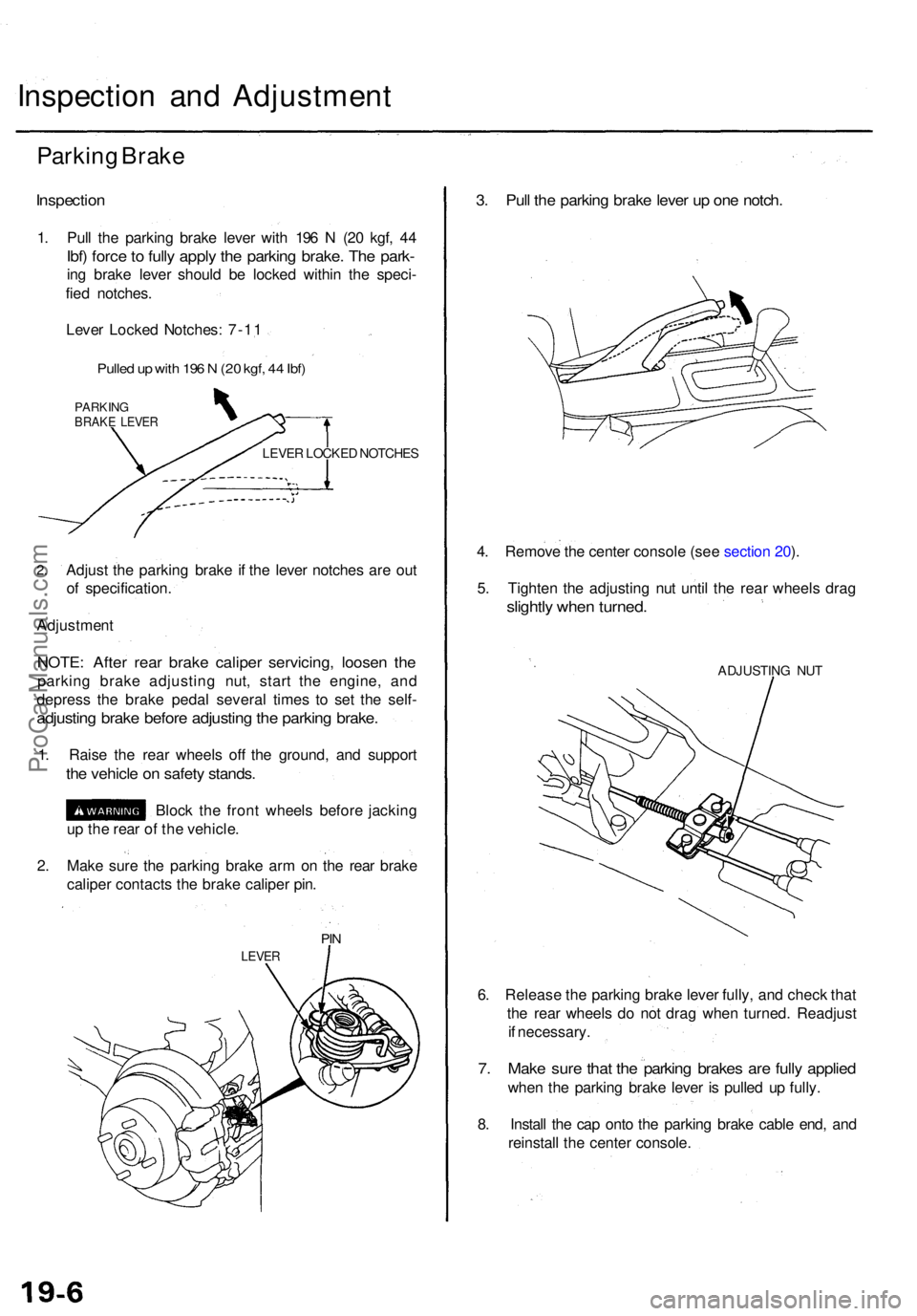
1. Pul l th e parkin g brak e leve r wit h 19 6 N (2 0 kgf , 4 4
Ibf) forc e to full y appl y th e parkin g brake . Th e park -
ing brak e leve r shoul d b e locke d withi n th e speci -
fie d notches .
Leve r Locke d Notches : 7-1 1
Pulle d u p wit h 19 6 N (2 0 kgf , 4 4 Ibf )
PARKIN GBRAKE LEVE R
LEVER LOCKE D NOTCHE S
2.Adjus t th e parkin g brak e i f th e leve r notche s ar e ou t
o f specification .
Adjustmen t
NOTE: Afte r rea r brak e calipe r servicing , loose n th e
parkin g brak e adjustin g nut , star t th e engine , an d
depres s th e brak e peda l severa l time s t o se t th e self -
adjustin g brak e befor e adjustin g th e parkin g brake .
1. Rais e th e rea r wheel s of f th e ground , an d suppor t
the vehicl e o n safet y stands .
Block th e fron t wheel s befor e jackin g
u p th e rea r o f th e vehicle .
2 . Mak e sur e th e parkin g brak e ar m o n th e rea r brak e
calipe r contact s th e brak e calipe r pin .
PIN
LEVE R
3. Pul l th e parkin g brak e leve r u p on e notch .
4. Remov e th e cente r consol e (se e sectio n 20 ).
5 . Tighte n th e adjustin g nu t unti l th e rea r wheel s dra g
slightl y whe n turned .
ADJUSTIN G NU T
6. Releas e th e parkin g brak e leve r fully , an d chec k tha t
th e rea r wheel s d o no t dra g whe n turned . Readjus t
i f necessary .
7. Mak e sur e tha t th e parkin g brake s ar e full y applie d
when th e parkin g brak e leve r i s pulle d u p fully .
8 . Instal l th e ca p ont o th e parkin g brak e cabl e end , an d
reinstal l th e cente r console .
ProCarManuals.com
Page 1257 of 1771
Front Brake Caliper
Disassembly
• Never use an air hose or dry brush to clean brake
assemblies.
• Use an OSHA-approved vacuum cleaner to avoid
breathing brake dust.
CAUTION:
• Do not spill brake fluid on the vehicle; it may damage
the paint; if brake fluid does contact the paint, wash
it off immediately with water.
• To prevent spills, cover the hose joints with rags or
shop towels.
• Clean all parts in brake fluid and air dry; blow out all
passages with compressed air.
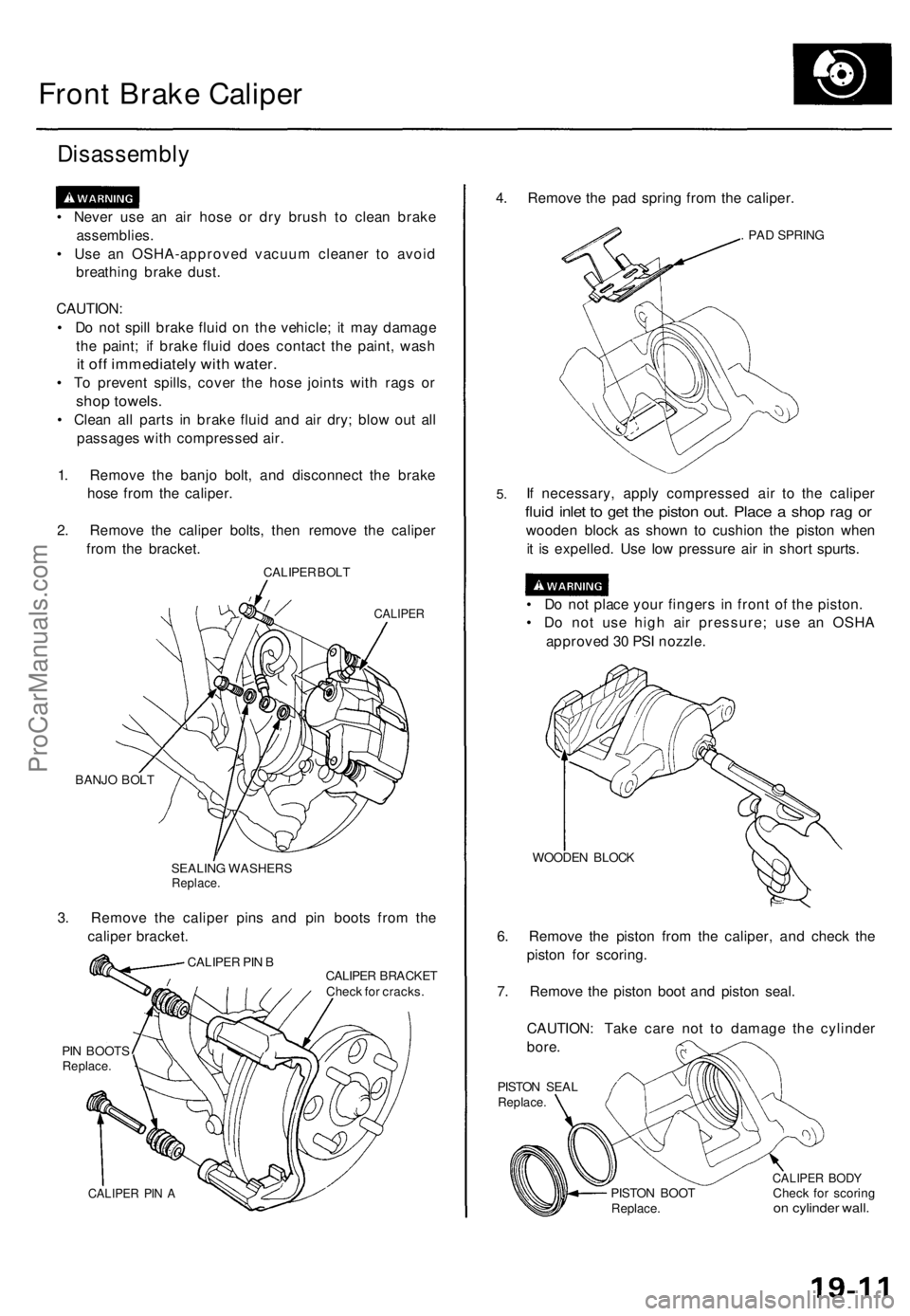
1. Remove the banjo bolt, and disconnect the brake
hose from the caliper.
2. Remove the caliper bolts, then remove the caliper
from the bracket.
CALIPER BOLT
CALIPER
BANJO BOLT
SEALING WASHERS
Replace.
3. Remove the caliper pins and pin boots from the
caliper bracket.
CALIPER BRACKET
Check for cracks.
PIN BOOTS
Replace.
CALIPER PIN A
4. Remove the pad spring from the caliper.
. PAD SPRING
5.
If necessary, apply compressed air to the caliper
fluid inlet to get the piston out. Place a shop rag or
wooden block as shown to cushion the piston when
it is expelled. Use low pressure air in short spurts.
• Do not place your fingers in front of the piston.
• Do not use high air pressure; use an OSHA
approved 30 PSI nozzle.
WOODEN BLOCK
6. Remove the piston from the caliper, and check the
piston for scoring.
7. Remove the piston boot and piston seal.
CAUTION: Take care not to damage the cylinder
bore.
PISTON SEAL
Replace.
PISTON BOOT
Replace.
CALIPER BODY
Check for scoring
on cylinder wall.
CALIPER PIN BProCarManuals.com
Page 1260 of 1771
Master Cylinde r
Removal
CAUTION :
• B e carefu l no t t o ben d o r damag e th e brak e line s whe n
removin g th e maste r cylinder .
• D o no t spil l brak e flui d o n th e vehicle ; i t ma y damag e
th e paint ; i f brak e flui d doe s contac t th e paint , was h
i t of f immediatel y wit h water .
• T o preven t spills , cove r th e hos e joint s wit h rag s o r
sho p towels .
NOTE : '9 5 - 9 6 mode l i s shown .
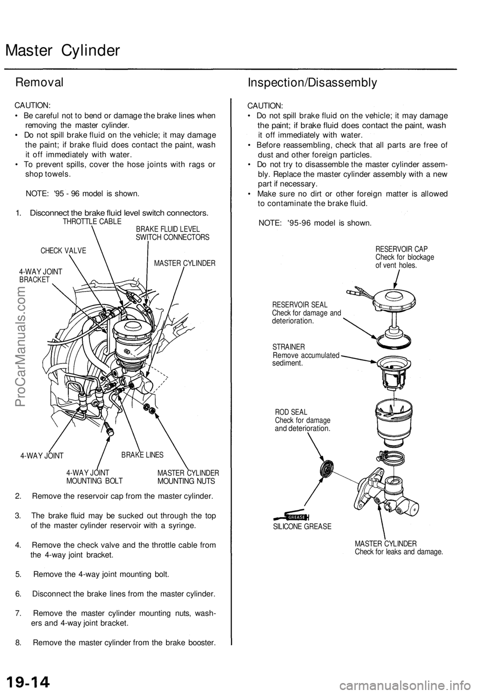
1. Disconnec t th e brak e flui d leve l switc h connectors .THROTTLE CABL EBRAKE FLUI D LEVE LSWITC H CONNECTOR S
CHECK VALV E
MASTE R CYLINDE R4-WAY JOIN TBRACKE T
4-WAY JOIN T
4-WA Y JOIN TMOUNTIN G BOL TMASTE R CYLINDE RMOUNTING NUT S
2. Remov e th e reservoi r ca p fro m th e maste r cylinder .
3 . Th e brak e flui d ma y b e sucke d ou t throug h th e to p
o f th e maste r cylinde r reservoi r wit h a syringe .
4 . Remov e th e chec k valv e an d th e throttl e cabl e fro m
th e 4-wa y join t bracket .
5 . Remov e th e 4-wa y join t mountin g bolt .
6 . Disconnec t th e brak e line s fro m th e maste r cylinder .
7 . Remov e th e maste r cylinde r mountin g nuts , wash -
er s an d 4-wa y join t bracket .
8 . Remov e th e maste r cylinde r fro m th e brak e booster .
Inspection/Disassembl y
CAUTION:
• D o no t spil l brak e flui d o n th e vehicle ; i t ma y damag e
the paint ; i f brak e flui d doe s contac t th e paint , was h
it of f immediatel y wit h water .
• Befor e reassembling , chec k tha t al l part s ar e fre e o f
dus t an d othe r foreig n particles .
• D o no t tr y t o disassembl e th e maste r cylinde r assem -
bly . Replac e th e maste r cylinde r assembl y wit h a ne w
par t i f necessary .
• Mak e sur e n o dir t o r othe r foreig n matte r i s allowe d
t o contaminat e th e brak e fluid .
NOTE : '95-9 6 mode l i s shown .
RESERVOI R SEA LCheck fo r damag e an ddeterioration .
STRAINERRemove accumulate dsediment.
RESERVOI R CA PChec k fo r blockag eof ven t holes .
ROD SEA LCheck fo r damag eand deterioration .
SILICONE GREAS E
MASTER CYLINDE RCheck fo r leak s an d damage .
BRAKE LINE S
ProCarManuals.com