1995 ACURA TL lock
[x] Cancel search: lockPage 1294 of 1771
Anti-lock Brake System (ABS)
Operation (cont'd)
Proportioning Control Valve Function:
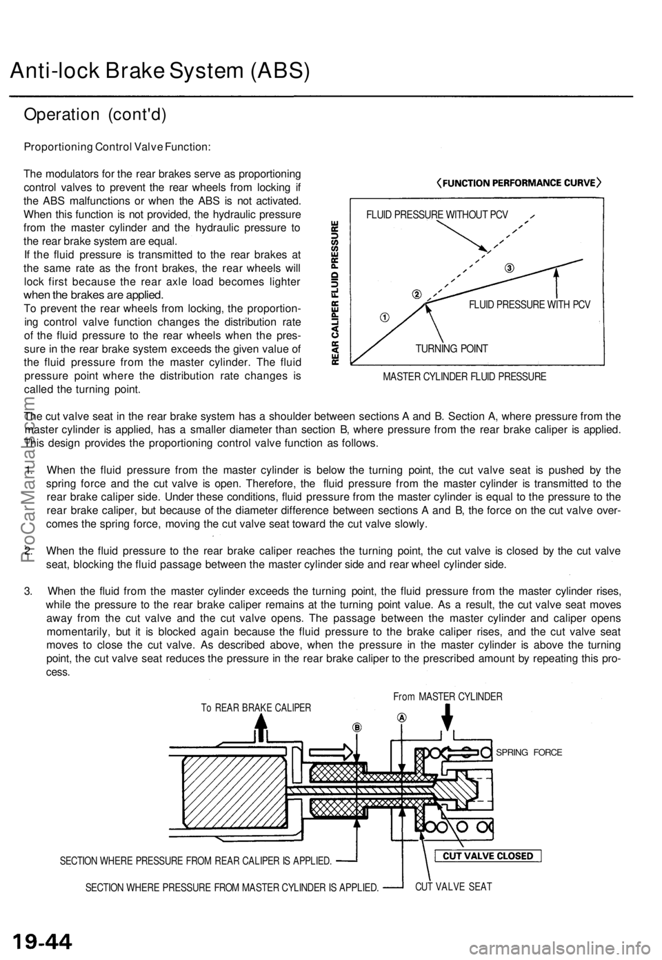
The modulators for the rear brakes serve as proportioning
control valves to prevent the rear wheels from locking if
the ABS malfunctions or when the ABS is not activated.
When this function is not provided, the hydraulic pressure
from the master cylinder and the hydraulic pressure to
the rear brake system are equal.
If the fluid pressure is transmitted to the rear brakes at
the same rate as the front brakes, the rear wheels will
lock first because the rear axle load becomes lighter
when the brakes are applied.
To prevent the rear wheels from locking, the proportion-
ing control valve function changes the distribution rate
of the fluid pressure to the rear wheels when the pres-
sure in the rear brake system exceeds the given value of
the fluid pressure from the master cylinder. The fluid
pressure point where the distribution rate changes is
called the turning point.
FLUID PRESSURE WITHOUT PCV
FLUID PRESSURE WITH PCV
TURNING POINT
MASTER CYLINDER FLUID PRESSURE
The cut valve seat in the rear brake system has a shoulder between sections A and B. Section A, where pressure from the
master cylinder is applied, has a smaller diameter than section B, where pressure from the rear brake caliper is applied.
This design provides the proportioning control valve function as follows.
1. When the fluid pressure from the master cylinder is below the turning point, the cut valve seat is pushed by the
spring force and the cut valve is open. Therefore, the fluid pressure from the master cylinder is transmitted to the
rear brake caliper side. Under these conditions, fluid pressure from the master cylinder is equal to the pressure to the
rear brake caliper, but because of the diameter difference between sections A and B, the force on the cut valve over-
comes the spring force, moving the cut valve seat toward the cut valve slowly.
2. When the fluid pressure to the rear brake caliper reaches the turning point, the cut valve is closed by the cut valve
seat, blocking the fluid passage between the master cylinder side and rear wheel cylinder side.
3. When the fluid from the master cylinder exceeds the turning point, the fluid pressure from the master cylinder rises,
while the pressure to the rear brake caliper remains at the turning point value. As a result, the cut valve seat moves
away from the cut valve and the cut valve opens. The passage between the master cylinder and caliper opens
momentarily, but it is blocked again because the fluid pressure to the brake caliper rises, and the cut valve seat
moves to close the cut valve. As described above, when the pressure in the master cylinder is above the turning
point, the cut valve seat reduces the pressure in the rear brake caliper to the prescribed amount by repeating this pro-
cess.
From MASTER CYLINDER
To REAR BRAKE CALIPER
SPRING FORCE
SECTION WHERE PRESSURE FROM REAR CALIPER IS APPLIED.
SECTION WHERE PRESSURE FROM MASTER CYLINDER IS APPLIED.
CUT VALVE SEATProCarManuals.com
Page 1306 of 1771
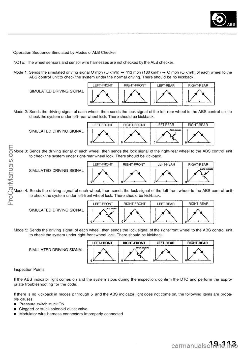
Operation Sequence Simulated by Modes of ALB Checker
NOTE: The wheel sensors and sensor wire harnesses are not checked by the ALB checker.
Mode 1: Sends the simulated driving signal O mph (O km/h) 113 mph (180 km/h) O mph (O km/h) of each wheel to the
ABS control unit to check the system under the normal driving. There should be no kickback.
SIMULATED DRIVING SIGNAL
LEFT-FRONT
RIGHT-FRONT
LEFT-REAR
RIGHT-REAR
Mode 2: Sends the driving signal of each wheel, then sends the lock signal of the left-rear wheel to the ABS control unit to
check the system under left-rear wheel lock. There should be kickback.
SIMULATED DRIVING SIGNAL
LEFT-FRONT
RIGHT-FRONT
LEFT-REAR
RIGHT-REAR
Mode 3: Sends the driving signal of each wheel, then sends the lock signal of the right-rear wheel to the ABS control unit
to check the system under right-rear wheel lock. There should be kickback.
SIMULATED DRIVING SIGNAL
LEFT-FRONT
RIGHT-FRONT
LEFT-REAR
RIGHT-REAR
Mode 4: Sends the driving signal of each wheel, then sends the lock signal of the left-front wheel to the ABS control unit
to check the system under left-front wheel lock. There should be kickback.
SIMULATED DRIVING SIGNAL
LEFT-FRONT
RIGHT-FRONT
LEFT-REAR
RIGHT-REAR
Mode 5: Sends the driving signal of each wheel, then sends the lock signal of the right-front wheel to the ABS control unit
to check the system under right-front wheel lock. There should be kickback.
SIMULATED DRIVING SIGNAL
Inspection Points
If the ABS indicator light comes on and the system stops during the inspection, confirm the DTC and perform the appro-
priate troubleshooting for the code.
If there is no kickback in modes 2 through 5, and the ABS indicator light does not come on, the following items are proba-
ble causes:
Pressure switch stuck ON
Clogged or stuck solenoid outlet valve
Modulator wire harness connectors improperly connectedProCarManuals.com
Page 1313 of 1771
Wire Harnes s Replacemen t
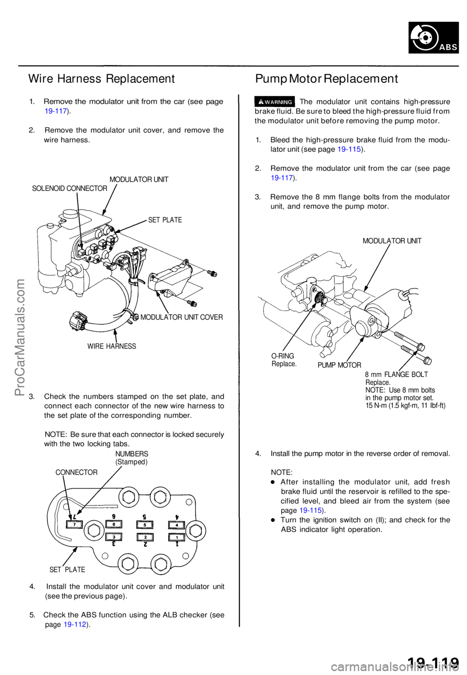
1. Remov e th e modulato r uni t fro m th e ca r (se e pag e
19-117 ).
2 . Remov e th e modulato r uni t cover , an d remov e th e
wir e harness .
MODULATO R UNI T
SOLENOI D CONNECTO R
SET PLAT E
MODULATO R UNI T COVE R
WIRE HARNES S
3. Chec k th e number s stampe d o n th e se t plate , an d
connec t eac h connecto r o f th e ne w wir e harnes s t o
th e se t plat e o f th e correspondin g number .
NOTE : B e sur e tha t eac h connecto r i s locke d securel y
wit h th e tw o lockin g tabs .
NUMBER S(Stamped )
CONNECTO R
SET PLAT E
4. Instal l th e modulato r uni t cove r an d modulato r uni t
(se e th e previou s page) .
5 . Chec k th e AB S functio n usin g th e AL B checke r (se e
page 19-112 ).
Pum p Moto r Replacemen t
The modulato r uni t contain s high-pressur e
brak e fluid . B e sur e to blee d th e high-pressur e flui d fro m
th e modulato r uni t befor e removin g th e pum p motor .
1 . Blee d th e high-pressur e brak e flui d fro m th e modu -
lato r uni t (se e pag e 19-115 ).
2 . Remov e th e modulato r uni t fro m th e ca r (se e pag e
19-117 ).
3 . Remov e th e 8 m m flang e bolt s fro m th e modulato r
unit , an d remov e th e pum p motor .
MODULATO R UNI T
O-RIN GReplace .PUMP MOTO R
8 m m FLANG E BOL TReplace .NOTE: Us e 8 m m bolt sin th e pum p moto r set .15 N- m (1. 5 kgf-m , 1 1 Ibf-ft )
4. Instal l th e pum p moto r i n th e revers e orde r o f removal .
NOTE:
After installin g th e modulato r unit , ad d fres h
brak e flui d unti l th e reservoi r i s refille d t o th e spe -
cifie d level , an d blee d ai r fro m th e syste m (se e
page 19-115 ).
Tur n th e ignitio n switc h o n (II) ; an d chec k fo r th e
AB S indicato r ligh t operation .
ProCarManuals.com
Page 1323 of 1771
Anti-lock Brak e Syste m (ABS )
Features/Constructio n
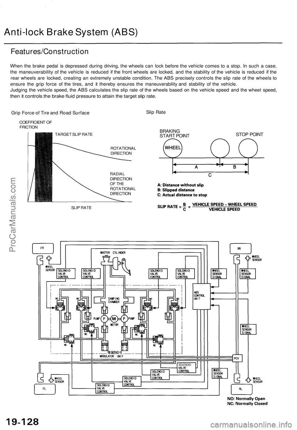
When th e brak e peda l i s depresse d durin g driving , th e wheel s ca n loc k befor e th e vehicl e come s t o a stop . I n suc h a case ,
th e maneuverabilit y o f th e vehicl e i s reduce d i f th e fron t wheel s ar e locked , an d th e stabilit y o f th e vehicl e i s reduce d i f th e
rea r wheel s ar e locked , creatin g a n extremel y unstabl e condition . Th e AB S precisel y control s th e sli p rat e o f th e wheel s t o
ensur e th e gri p forc e o f th e tires , an d i t thereb y ensure s th e
maneuverability an d stabilit y o f th e vehicle .
Judgin g th e vehicl e speed , th e AB S calculate s th e sli p rat e o f th e wheel s base d o n th e vehicl e spee d an d th e whee l speed ,
then it control s th e brak e flui d pressur e to attai n th e targe t sli p rate .
Grip Forc e o f Tir e an d Roa d Surfac e Sli
p Rat e
COEFFICIEN T O FFRICTIO N
TARGET SLI P RAT E
SLI P RAT E ROTATIONA
L
DIRECTIO N
RADIALDIRECTIO NOF TH EROTATIONA L
DIRECTIO N
BRAKINGSTART POIN T STO
P POIN T
SOLENOI D
ProCarManuals.com
Page 1325 of 1771
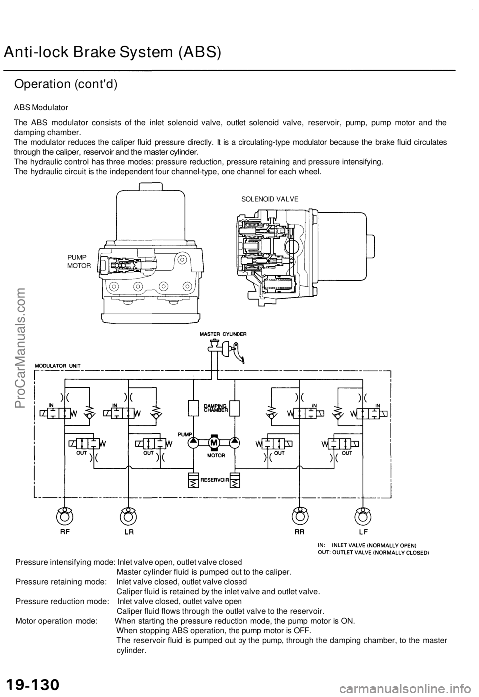
Anti-lock Brake System (ABS)
Operation (cont'd)
ABS Modulator
The ABS modulator consists of the inlet solenoid valve, outlet solenoid valve, reservoir, pump, pump motor and the
damping chamber.
The modulator reduces the caliper fluid pressure directly. It is a circulating-type modulator because the brake fluid circulates
through the caliper, reservoir and the master cylinder.
The hydraulic control has three modes: pressure reduction, pressure retaining and pressure intensifying.
The hydraulic circuit is the independent four channel-type, one channel for each wheel.
PUMP
MOTOR
Pressure intensifying mode: Inlet valve open, outlet valve closed
Master cylinder fluid is pumped out to the caliper.
Pressure retaining mode: Inlet valve closed, outlet valve closed
Caliper fluid is retained by the inlet valve and outlet valve.
Pressure reduction mode: Inlet valve closed, outlet valve open
Caliper fluid flows through the outlet valve to the reservoir.
Motor operation mode: When starting the pressure reduction mode, the pump motor is ON.
When stopping ABS operation, the pump motor is OFF.
The reservoir fluid is pumped out by the pump, through the damping chamber, to the master
cylinder.
SOLENOID VALVEProCarManuals.com
Page 1342 of 1771
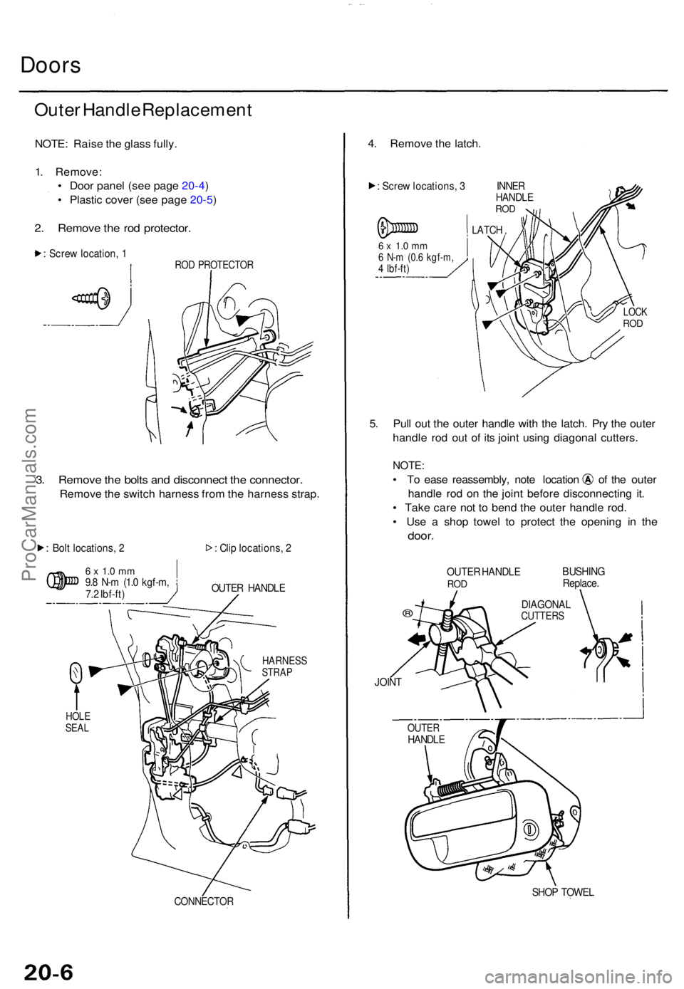
Doors
Outer Handl e Replacemen t
NOTE: Rais e th e glas s fully .
1 . Remove :
• Doo r pane l (se e pag e 20-4 )
• Plasti c cove r (se e pag e 20-5 )
2. Remov e th e ro d protector .
: Scre w location , 1RO D PROTECTO R
3. Remov e th e bolt s an d disconnec t th e connector .
Remove th e switc h harnes s fro m th e harnes s strap .
: Bol t locations , 2
6 x 1. 0 m m9.8 N- m (1. 0 kgf-m ,
7. 2 Ibf-ft ) :
Cli p locations , 2
OUTE R HANDL E
CONNECTO R
4. Remov e th e latch .
: Scre w locations , 3 INNE RHANDLEROD
6 x 1. 0 m m6 N- m (0. 6 kgf-m ,4 Ibf-ft )
LATCH
5. Pul l ou t th e oute r handl e wit h th e latch . Pr y th e oute r
handl e ro d ou t o f it s join t usin g diagona l cutters .
NOTE:
• T o eas e reassembly , not e locatio n o f th e oute r
handl e ro d o n th e join t befor e disconnectin g it .
• Tak e car e no t t o ben d th e oute r handl e rod .
• Us e a sho p towe l t o protec t th e openin g i n th e
door .
OUTE R HANDL ERODBUSHIN G
Replace .
®
JOINT
SHOP TOWE L
DIAGONA LCUTTERS
HARNES SSTRAP
HOLESEALOUTE RHANDL E
LOCKROD
ProCarManuals.com
Page 1343 of 1771
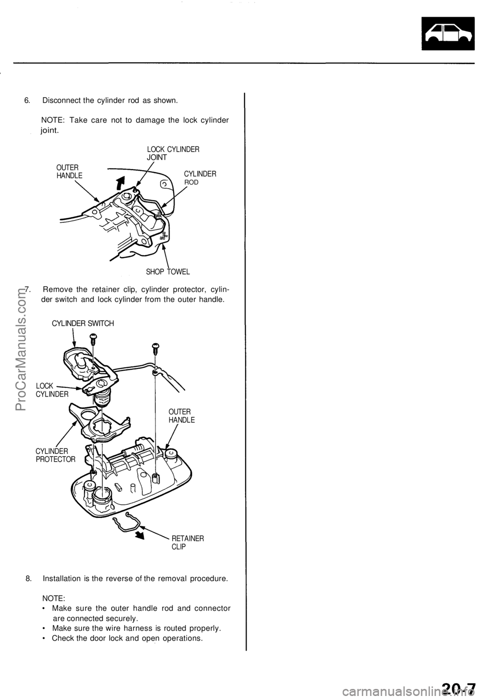
6. Disconnect the cylinder rod as shown.
NOTE: Take care not to damage the lock cylinder
joint.
LOCK CYLINDER
JOINT
OUTER
HANDLE
CYLINDER
ROD
SHOP TOWEL
7. Remove the retainer clip, cylinder protector, cylin-
der switch and lock cylinder from the outer handle.
CYLINDER SWITCH
LOCK
CYLINDER
CYLINDER
PROTECTOR
OUTER
HANDLE
RETAINER
CLIP
8. Installation is the reverse of the removal procedure.
NOTE:
• Make sure the outer handle rod and connector
are connected securely.
• Make sure the wire harness is routed properly.
• Check the door lock and open operations.ProCarManuals.com
Page 1345 of 1771
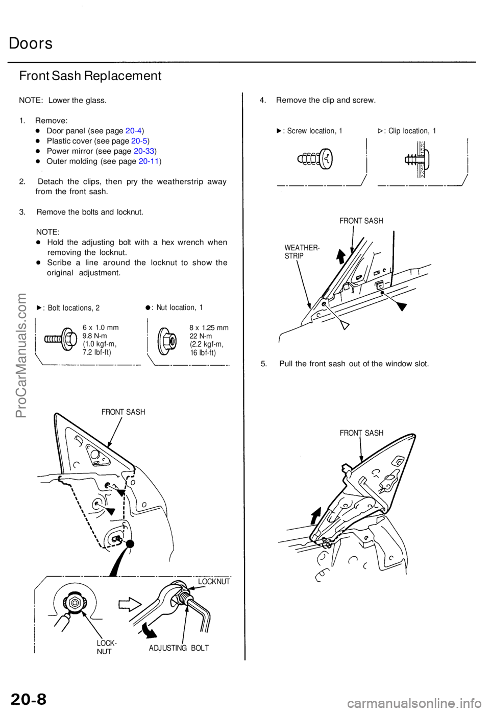
Doors
Front Sas h Replacemen t
NOTE: Lowe r th e glass .
1 . Remove :
Doo r pane l (se e pag e 20-4 )
Plasti c cove r (se e pag e 20-5 )
Powe r mirro r (se e pag e 20-33 )
Oute r moldin g (se e pag e 20-11 )
2 . Detac h th e clips , the n pr y th e weatherstri p awa y
fro m th e fron t sash .
3 . Remov e th e bolt s an d locknut .
NOTE:
Hold th e adjustin g bol t wit h a he x wrenc h whe n
removin g th e locknut .
Scrib e a lin e aroun d th e locknu t t o sho w th e
origina l adjustment .
: Bol t locations , 2 :
Nu t location , 1
6 x 1. 0 m m9.8 N- m(1.0 kgf-m ,7.2 Ibf-ft )
8 x 1.2 5 mm22 N- m(2.2 kgf-m ,16 Ibf-ft )
FRON T SAS H
LOCK -NUTADJUSTIN G BOL T
4. Remov e th e cli p an d screw .
: Scre w location , 1 : Cli p location , 1
FRON T SAS H
WEATHER -
STRI P
5. Pul l th e fron t sas h ou t o f th e windo w slot .
FRON T SAS H
LOCKNU T
ProCarManuals.com