Page 1469 of 1771

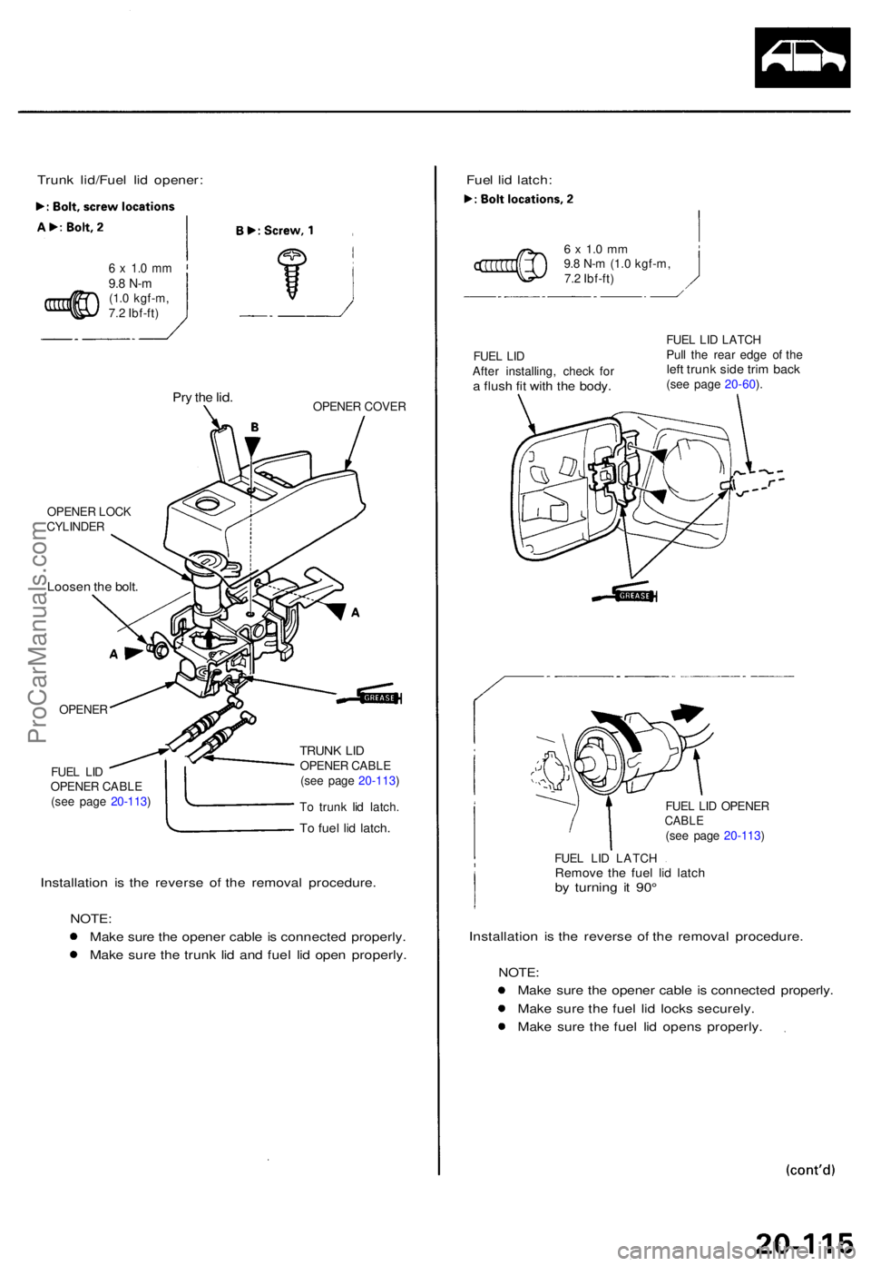
Trunk lid/Fue l li d opener :
6 x 1. 0 m m9.8 N- m(1.0 kgf-m ,
7. 2 Ibf-ft )
Pry th e lid .OPENE R COVE R
OPENE R LOC K
CYLINDE R
Loosen th e bolt .
OPENE R
FUE L LI D
OPENE R CABL E
(se e pag e 20-113 )
TRUNK LI DOPENE R CABL E
(se e pag e 20-113 )
T o trun k li d latch .
To fue l li d latch .
Installatio n i s th e revers e o f th e remova l procedure .
NOTE :
Mak e sur e th e opene r cabl e is connecte d properly .
Mak e sur e th e trun k li d an d fue l li d ope n properly . Fue
l li d latch :
6 x 1. 0 m m9.8 N- m (1. 0 kgf-m ,
7. 2 Ibf-ft )
FUE L LI D
Afte r installing , chec k fo r
a flus h fi t wit h th e body .
FUEL LI D LATC H
Pul l th e rea r edg e o f th e
left trun k sid e tri m bac k(see pag e 20-60 ).
FUE L LI D OPENE R
CABLE(see pag e 20-113 )
FUE L LI D LATC H
Remove th e fue l li d latc hby turnin g i t 90 °
Installatio n i s th e revers e o f th e remova l procedure .
NOTE:
Make sur e th e opene r cabl e is connecte d properly .
Mak e sur e th e fue l li d lock s securely .
Mak e sur e th e fue l li d open s properly .
ProCarManuals.com
Page 1470 of 1771

Opener an d Latc h
Replacemen t (cont'd )
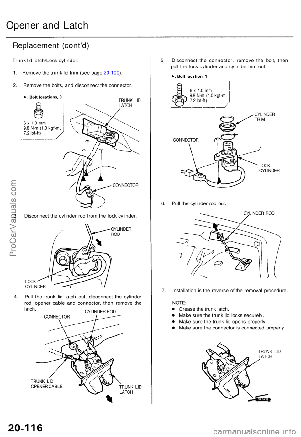
Trunk li d latch/Loc k cylinder :
1 . Remov e th e trun k li d tri m (se e pag e 20-100 ).
2 . Remov e th e bolts , an d disconnec t th e connector .
TRUNK LI DLATC H
6 x 1. 0 m m9.8 N- m (1. 0 kgf-m ,
7. 2 Ibf-ft )
CONNECTOR
3. Disconnec t th e cylinde r ro d fro m th e loc k cylinder .
CYLINDE RROD
LOC KCYLINDE R
4. Pul l th e trun k li d latc h out , disconnec t th e cylinde r
rod , opene r cabl e an d connector , the n remov e th e
latch .
CONNECTO RCYLINDE
R RO D
TRUN K LI D
OPENE R CABL E
TRUNK LI D
LATC H
5. Disconnec t th e connector , remov e th e bolt , the n
pul l th e loc k cylinde r an d cylinde r tri m out .
6 x 1. 0 m m9.8 N- m (1. 0 kgf-m ,
7. 2 Ibf-ft )
CONNECTO R
CYLINDERTRIM
LOC KCYLINDE R
6. Pul l th e cylinde r ro d out .
CYLINDE R RO D
7. Installatio n i s th e revers e o f th e remova l procedure .
NOTE:
Greas e th e trun k latch .
Mak e sur e th e trun k li d lock s securely .
Mak e sur e th e trun k li d open s properly .
Mak e sur e th e connecto r i s connecte d properly .
TRUNK LI D
LATC H
ProCarManuals.com
Page 1471 of 1771
Hood Latc h
Replacemen t
NOTE: Tak e car e no t t o ben d th e opene r cables .
1. Ope n th e hood , an d remov e th e fron t bulkhea d
cover (se e pag e 20-6 ).
2 . Remov e th e hoo d latch , an d disconnec t th e hoo d
opene r cabl e an d hoo d latc h switc h connector .
HOOD LATC H
SWITC H CONNECTO R
HOO D OPENE R
CABLE
3. Installatio n i s th e revers e o f th e remova l procedure .
NOTE :
• Mak e sur e th e hoo d opene r cabl e i s connecte d
properly.
• Mak e sur e th e hoo d lock s securely .
HOODLATC H
ProCarManuals.com
Page 1490 of 1771
Illustrated Inde x
HEATER/EVAPORATOR/BLOWE R UNITHEATE R UNI T
Replacement , pag e 22-6 3
Heate r Cor e Replacement , pag e 22-6 5
EVAPORATO RReplacement, pag e 22-5 8
Overhaul , pag e 22-6 0
BLOWE R UNI T
Replacement , pag e 22-6 1
Overhaul , pag e 22-6 2
SERVIC E VALV E
(HIGH-PRESSUR E SIDE )
EXPANSION VALV E
Replacement , pag e 22-5 8
CONDENSE R
Replacement , pag e 22-7 9
A/ C PRESSUR E SWITC H
Whe n th e refrigeran t pressur e i s belo w 20 0 kP a (2. 0 kgf/cm
2,
2 8 psi ) du e t o refrigeran t leakag e o r abov e 3,20 0 kP a (3 2 kgf/cm2,45 5 psi ) du e to refrigeran t blockage , th e A/ C pressur e switc hopens th e circui t t o th e A/ C switc h an d stop s th e ai r conditionin gto protec t th e compressor .
SERVICE VALV E
(LOW-PRESSUR E SIDE )
COMPRESSO RReplacement, pag e 22-7 2
Clutc h Inspection , pag e 22-7 5
Clutc h Overhaul , pag e 22-7 6
Relie f Valv e Replacement , pag e 22-7 7
RECEIVER/DRYE R
ProCarManuals.com
Page 1503 of 1771
Outside Ai r Temperatur e Senso r
Replacemen t
1. Disconnec t th e 2 P connecto r fro m th e outsid e ai r
temperatur e sensor .
2 . Releas e th e lock , an d remov e th e outsid e ai r tem -
peratur e sensor .
OUTSID E AI R TEMPERATUR E SENSO R
LOCK
3. Instal l i n th e revers e orde r o f removal .
Test
Compar e th e resistanc e readin g betwee n th e No . 1 an d
No . 2 terminal s o f th e outsid e ai r temperatur e senso r wit h
th e specification s show n i n followin g graph ; resistanc e
shoul d b e withi n specifications .
NOTE : Di p th e senso r i n ic e water , an d measur e resis -
tance . The n pou r ho t wate r o n th e sensor , an d chec k fo r
chang e in resistance .
CAUTION : Th e senso r use s a thermisto r whic h ca n b e
damage d i f hig h curren t i s applie d durin g testing .
Therefore , us e a circui t teste r wit h a n outpu t o f 1 m A o r
les s a t th e 2 0 k range .
OUTSIDE AI R TEMPERATUR E SENSO R
TEMPERATUR E
ProCarManuals.com
Page 1505 of 1771

Evaporator Temperatur e
Sensor Powe r Transisto r
TestTes t
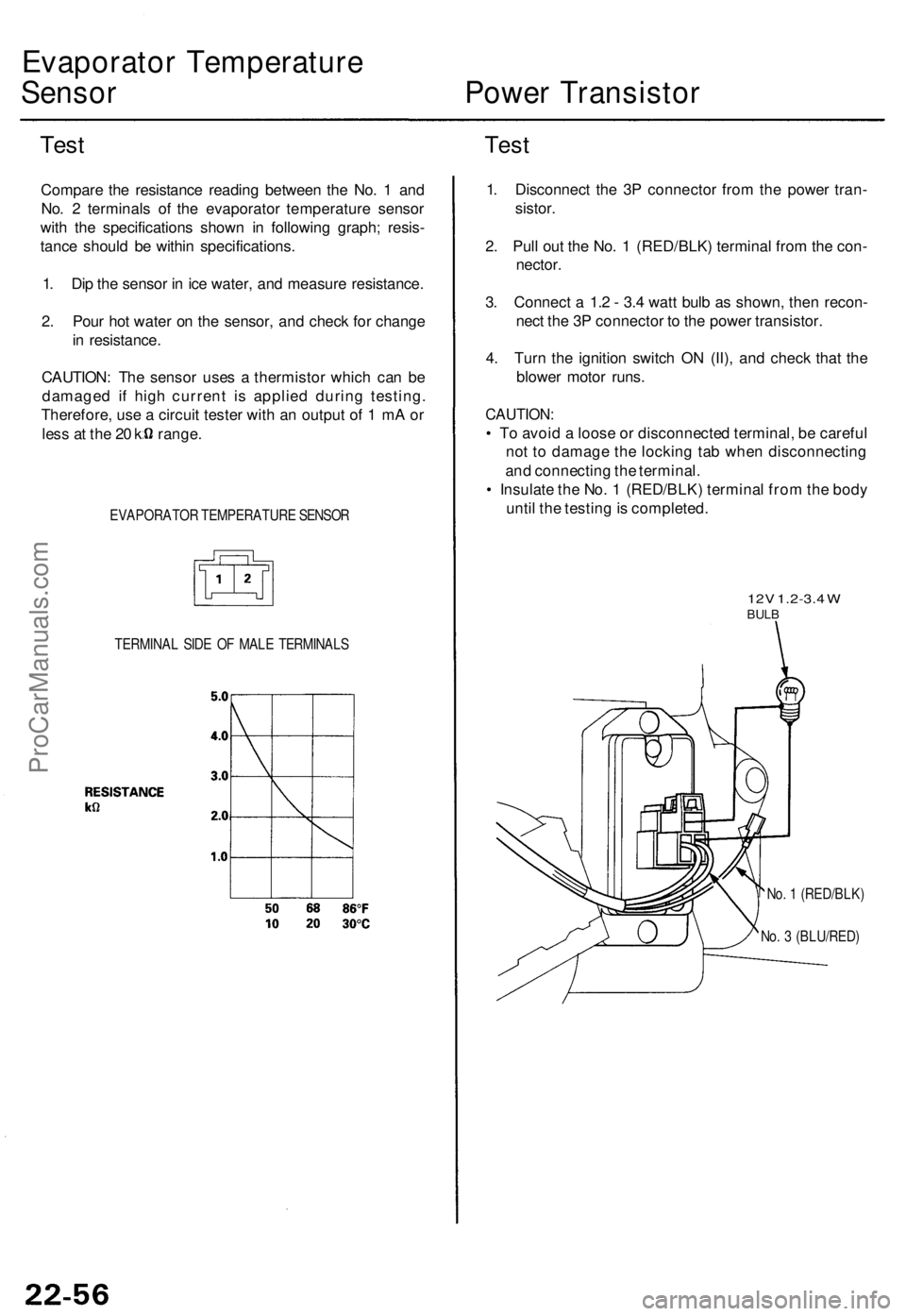
Compar e th e resistanc e readin g betwee n th e No . 1 an d
No . 2 terminal s o f th e evaporato r temperatur e senso r
wit h th e specification s show n i n followin g graph ; resis -
tanc e shoul d b e withi n specifications .
1 . Di p th e senso r i n ic e water , an d measur e resistance .
2 . Pou r ho t wate r o n th e sensor , an d chec k fo r chang e
i n resistance .
CAUTION : Th e senso r use s a thermisto r whic h ca n b e
damage d i f hig h curren t i s applie d durin g testing .
Therefore , us e a circui t teste r wit h a n outpu t o f 1 m A o r
les s a t th e 2 0 k range .
EVAPORATO R TEMPERATUR E SENSO R
TERMINA L SID E O F MAL E TERMINAL S
1. Disconnec t th e 3 P connecto r fro m th e powe r tran -
sistor .
2 . Pul l ou t th e No . 1 (RED/BLK ) termina l fro m th e con -
nector .
3. Connec t a 1. 2 - 3. 4 wat t bul b a s shown , the n recon -
nec t th e 3 P connecto r t o th e powe r transistor .
4 . Tur n th e ignitio n switc h O N (II) , an d chec k tha t th e
blowe r moto r runs .
CAUTION :
• T o avoi d a loos e o r disconnecte d terminal , b e carefu l
no t t o damag e th e lockin g ta b whe n disconnectin g
an d connectin g th e terminal .
• Insulat e th e No . 1 (RED/BLK ) termina l fro m th e bod y
unti l th e testin g is completed .
12V 1.2-3. 4 WBUL B
No. 1 (RED/BLK )
No . 3 (BLU/RED )
ProCarManuals.com
Page 1527 of 1771
4.
Remove the screw from the field coil ground termi-
nal. Remove the snap ring A with snap ring pliers,
then remove the field coil.
NOTE:
Be careful not to damage the field coil and com-
pressor during removal/installation.
Once the snap ring A is removed, replace it with
a new
one.
SNAP RING A
Replace.
FIELD
COIL
5. Install in the reverse order of removal. Make note of
the following items.
Install the field coil with the wire side facing
down (see above).
Clean the pulley and compressor sliding surfaces
with non-petroleum solvent.
Make sure the snap rings are fully seated in the
groove.
Apply locking agent to the threads of the center
bolt, and tighten it securely.
Make sure that the pulley turns smoothly after
it's reassembled.ProCarManuals.com
Page 1536 of 1771

Troubleshooting
Tips and Precautions
Before Troubleshooting
Check applicable fuses in the appropriate fuse/relay
box.
Check the battery for damage, state of charge, and
clean and tight connections.
Check the alternator belt tension.
CAUTION:
Do not quick-charge a battery unless the battery
ground cable has been disconnected, otherwise you
will damage the alternator diodes.
Do not attempt to crank the engine with the battery
ground cable loosely connected or you will severely
damage the wiring.
Handling Connectors
Make sure the connectors are clean and have no loose
wire terminals.
Make sure multiple cavity connectors are packed with
grease (except waterproof connectors).
All connectors have push-down release type locks.
LOCKING TAB
Some connectors have a clip on their side used to
attach them to a mount bracket on the body or on
another component. This clip has a pull type lock.
Some mounted connectors cannot be disconnected
unless you first release the lock and remove the con-
nector from its mount bracket.
LOCKING
PAWL ON
OTHER
HALF OF
CONNECTOR
Pull to
disengage
BRACKET
Never try to disconnect connectors by pulling on
their wires; pull on the connector halves instead.
Always reinstall plastic covers.
Before connecting connectors, make sure the termi-
nals are in place and not bent.
BENT TERMINAL
Check for loose retainer and rubber seals.
RETAINER
RUBBER SEAL RETAINER
The backs of some connectors are packed with
grease. Add grease if necessary. If the grease is con-
taminated, replace it.
LOCKING TABProCarManuals.com