Page 1369 of 1771
Doors
Glass Adjustmen t (cont'd )
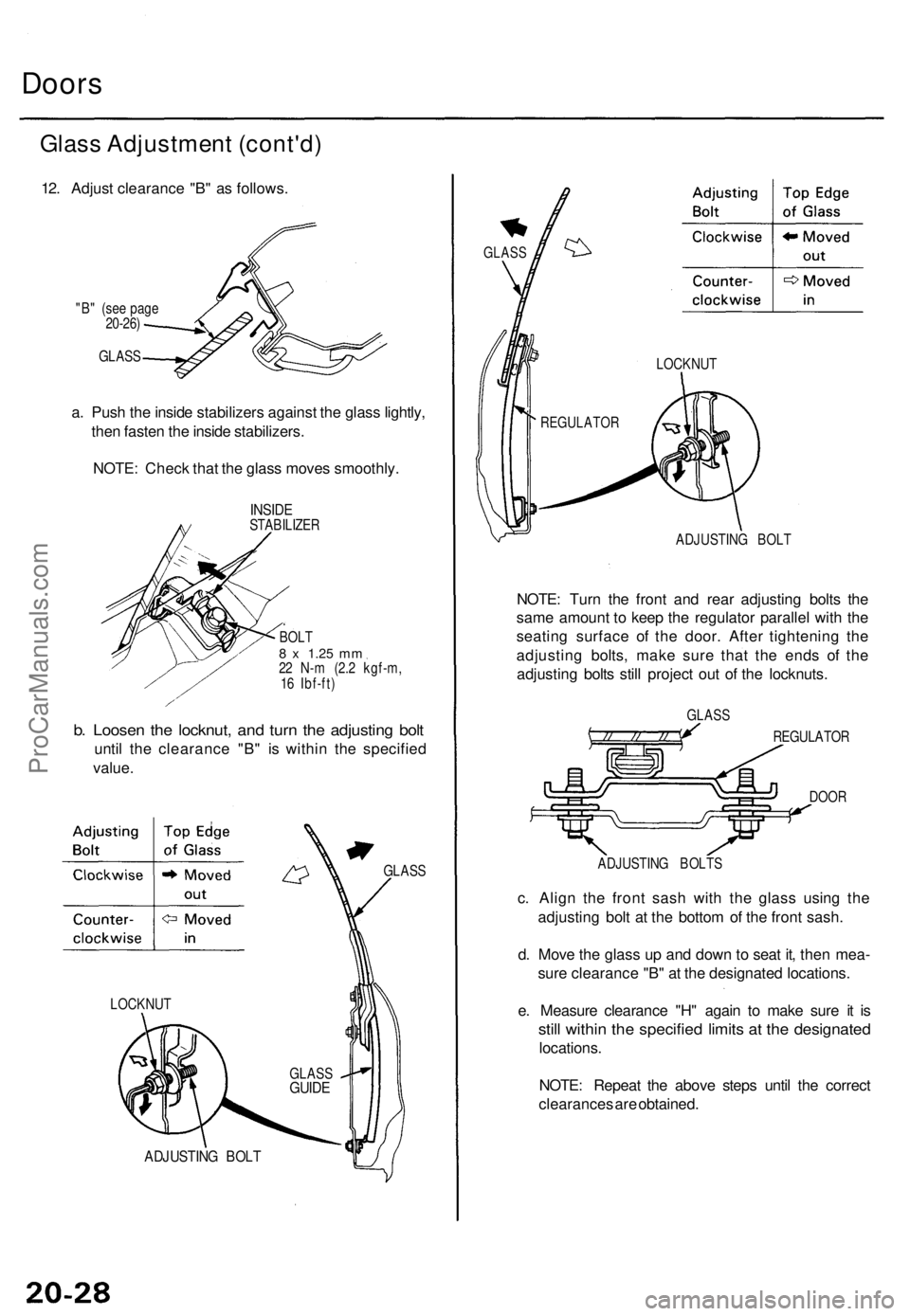
12. Adjus t clearanc e "B " a s follows .
"B" (se e pag e
20-26 )
GLAS S
a. Pus h th e insid e stabilizer s agains t th e glas s lightly ,
the n faste n th e insid e stabilizers .
NOTE : Chec k tha t th e glas s move s smoothly .
INSIDESTABILIZE R
BOLT8 x 1.2 5 mm22 N- m (2. 2 kgf-m ,
1 6 Ibf-ft )
b. Loose n th e locknut , an d tur n th e adjustin g bol t
unti l th e clearanc e "B " i s withi n th e specifie d
value .
LOCKNU T
ADJUSTIN G BOL T
GLAS S
GLAS S
GUIDE
GLAS S
ADJUSTIN G BOL T
NOTE: Tur n th e fron t an d rea r adjustin g bolt s th e
sam e amoun t t o kee p th e regulato r paralle l wit h th e
seatin g surfac e o f th e door . Afte r tightenin g th e
adjustin g bolts , mak e sur e tha t th e end s o f th e
adjustin g bolt s stil l projec t ou t o f th e locknuts .
GLASS
REGULATO R
DOO R
ADJUSTIN G BOLT S
c. Alig n th e fron t sas h wit h th e glas s usin g th e
adjustin g bol t a t th e botto m o f th e fron t sash .
d . Mov e th e glas s u p an d dow n to sea t it , the n mea -
sur e clearanc e "B " a t th e designate d locations .
e . Measur e clearanc e "H " agai n t o mak e sur e i t i s
stil l withi n th e specifie d limit s a t th e designate d
locations.
NOTE : Repea t th e abov e step s unti l th e correc t
clearance s ar e obtained .
LOCKNU T
REGULATO R
ProCarManuals.com
Page 1370 of 1771
Rear Door :
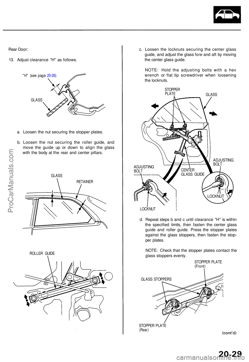
13 . Adjus t clearanc e "H " a s follows .
"H" (se e pag e 20-26 )
GLAS S
a. Loose n th e nu t securin g th e stoppe r plates .
b . Loose n th e nu t securin g th e rolle r guide , an d
mov e th e guid e u p o r dow n t o alig n th e glas s
wit h th e bod y a t th e rea r an d cente r pillars .
GLASS
RETAINER
ROLLE R GUID E
c. Loose n th e locknut s securin g th e cente r glas s
guide , an d adjus t th e glas s for e an d af t b y movin g
th e cente r glas s guide .
NOTE : Hol d th e adjustin g bolt s wit h a he x
wrenc h o r fla t ti p screwdrive r whe n loosenin g
th e locknuts .
STOPPERPLATEGLAS S
LOCKNU T
d. Repea t step s b an d c unti l clearanc e "H " i s withi n
th e specifie d limits , the n faste n th e cente r glas s
guid e an d rolle r guide . Pres s th e stoppe r plate s
agains t th e glas s stoppers , the n faste n th e stop -
pe r plates .
NOTE : Chec k tha t th e stoppe r plate s contac t th e
glas s stopper s evenly .
STOPPE R PLAT E
(Front )
GLAS S STOPPER S
STOPPE R PLAT E
(Rear)
ADJUSTIN GBOLT CENTE
R
GLAS S GUID E
ADJUSTIN GBOLT
LOCKNU T
ProCarManuals.com
Page 1371 of 1771
Doors
Glass Adjustmen t (cont'd )
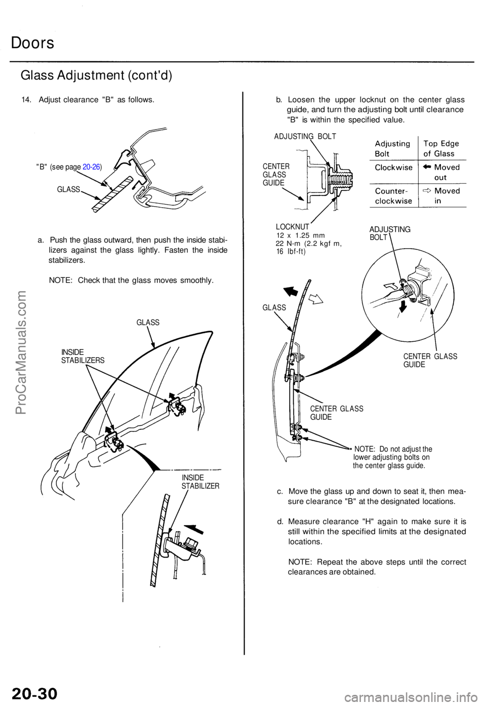
14. Adjus t clearanc e "B " a s follows .
"B" (se e pag e 20-26 )
GLAS S
a. Pus h th e glas s outward , the n pus h th e insid e stabi -
lizer s agains t th e glas s lightly . Faste n th e insid e
stabilizers .
NOTE : Chec k tha t th e glas s move s smoothly .
GLASS
INSIDESTABILIZER S
INSIDESTABILIZE R
b. Loose n th e uppe r locknu t o n th e cente r glas s
guide, an d tur n th e adjustin g bol t unti l clearanc e
"B" i s withi n th e specifie d value .
ADJUSTIN G BOL T
CENTE RGLASSGUIDE
LOCKNU T12 x 1.2 5 mm22 N- m (2. 2 kgf m ,16 Ibf-ft )
ADJUSTIN GBOLT
GLAS S
• NOTE : D o no t adjus t th elowe r adjustin g bolt s o nthe cente r glas s guide .
c. Mov e th e glas s u p an d dow n t o sea t it , the n mea -
sur e clearanc e "B " a t th e designate d locations .
d . Measur e clearanc e "H " agai n t o mak e sur e i t i s
stil l withi n th e specifie d limit s a t th e designate d
locations.
NOTE : Repea t th e abov e step s unti l th e correc t
clearance s ar e obtained .
CENTER GLAS SGUIDE
CENTE R GLAS SGUIDE
ProCarManuals.com
Page 1377 of 1771
Mirrors
Mirror Holder Replacement
1. Insert a screwdriver in the mirror housing through
the service hole, and loosen the actuator retaining
screw.
MIRROR
HOUSING
ACTUATOR
RETAINING
SCREW
SERVICE HOLE
2. Pull out the mirror holder from the mirror housing.
ACTUATOR
HOLDER
ACTUATOR
LOCK CAP
STOPPER
STOPPER
PIN
MIRROR
HOLDER
3. Pull the lock cap stopper and remove the stopper
pin, then separate the actuator and mirror holder.
NOTE: If the mirror is equipped with a defogger,
you cannot separate the actuator and mirror holder.
4. Installation is the reverse of the removal procedure.
NOTE: Apply grease to the locations indicated by
the arrows.ProCarManuals.com
Page 1398 of 1771
Glass an d Sunshad e Replacemen t
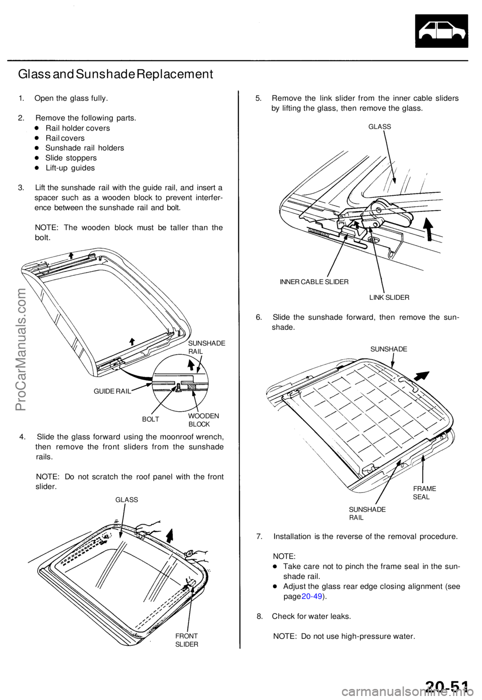
1. Ope n th e glas s fully .
2 . Remov e th e followin g parts .
Rai l holde r cover s
Rai l cover s
Sunshad e rai l holder s
Slid e stopper s
Lift-u p guide s
3 . Lif t th e sunshad e rai l wit h th e guid e rail , an d inser t a
space r suc h a s a woode n bloc k t o preven t interfer -
enc e betwee n th e sunshad e rai l an d bolt .
NOTE : Th e woode n bloc k mus t b e talle r tha n th e
bolt .
SUNSHAD ERAIL
GUID E RAI L
BOL TWOODE NBLOCK
4. Slid e th e glas s forwar d usin g th e moonroo f wrench ,
the n remov e th e fron t slider s fro m th e sunshad e
rails .
NOTE : D o no t scratc h th e roo f pane l wit h th e fron t
slider .
GLAS S
FRON TSLIDE R
5. Remov e th e lin k slide r fro m th e inne r cabl e slider s
b y liftin g th e glass , the n remov e th e glass .
GLAS S
INNER CABL E SLIDE R
LINK SLIDE R
6. Slid e th e sunshad e forward , the n remov e th e sun -
shade .
SUNSHAD E
FRAMESEAL
SUNSHAD ERAIL
7. Installatio n i s th e revers e o f th e remova l procedure .
NOTE:
Take car e no t t o pinc h th e fram e sea l i n th e sun -
shad e rail .
Adjus t th e glas s rea r edg e closin g alignmen t (se e
pag e 20-49 ).
8 . Chec k fo r wate r leaks .
NOTE : D o no t us e high-pressur e water .
ProCarManuals.com
Page 1404 of 1771
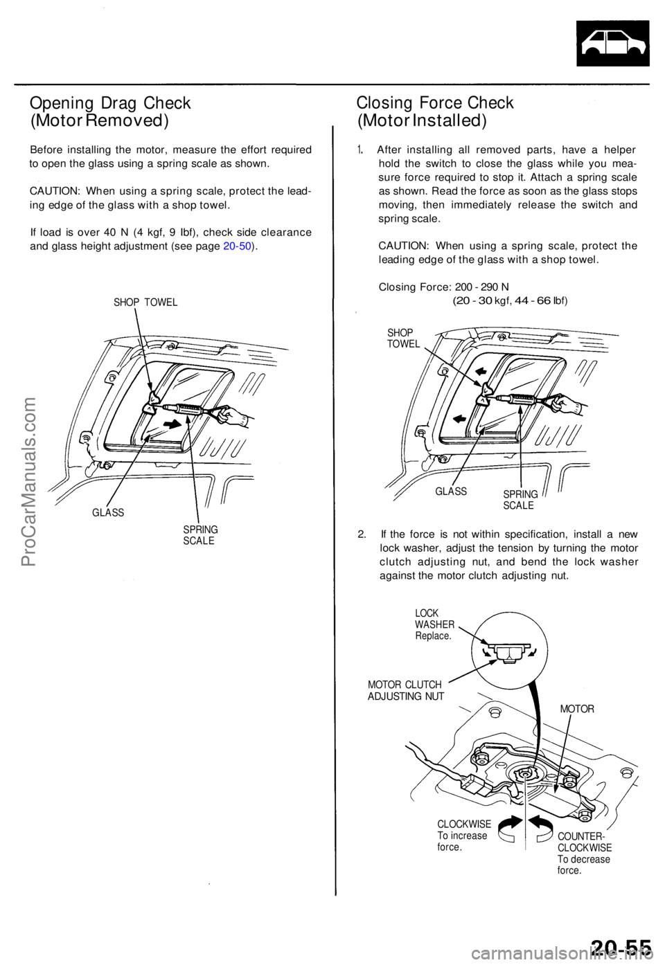
Opening Dra g Chec k
(Motor Removed )
Before installin g th e motor , measur e th e effor t require d
t o ope n th e glas s usin g a sprin g scal e a s shown .
CAUTION : Whe n usin g a sprin g scale , protec t th e lead -
in g edg e o f th e glas s wit h a sho p towel .
I f loa d i s ove r 4 0 N (4 kgf , 9 Ibf) , chec k sid e clearanc e
an d glas s heigh t adjustmen t (se e pag e 20-50 ).
SHO P TOWE L
GLAS S
SPRING
SCAL E
Closin g Forc e Chec k
(Moto r Installed )
1. Afte r installin g al l remove d parts , hav e a helpe r
hol d th e switc h t o clos e th e glas s whil e yo u mea -
sur e forc e require d t o sto p it . Attac h a sprin g scal e
a s shown . Rea d th e forc e a s soo n a s th e glas s stop s
moving , the n immediatel y releas e th e switc h an d
sprin g scale .
CAUTION : Whe n usin g a sprin g scale , protec t th e
leadin g edg e o f th e glas s wit h a sho p towel .
Closin g Force : 20 0 - 29 0 N
(2 0 - 3 0 kgf , 44 - 6 6 Ibf )
SHO P
TOWE L
SPRING
SCALE
2. I f th e forc e i s no t withi n specification , instal l a ne w
loc k washer , adjus t th e tensio n b y turnin g th e moto r
clutc h adjustin g nut , an d ben d th e loc k washe r
agains t th e moto r clutc h adjustin g nut .
LOC KWASHE RReplace .
MOTOR CLUTC HADJUSTIN G NU T
CLOCKWIS ETo increas eforce.COUNTER -CLOCKWIS ETo decreas e
force .
MOTO R
GLASS
ProCarManuals.com
Page 1413 of 1771
Carpet
Replacemen t
SRS component s ar e locate d in thi s area . Revie w th e SR S
componen t locations , precautions , an d procedure s i n th e
SR S (sectio n 24 ) befor e performin g repair s o r service .
1 . Remove :
Fron t sea t (se e pag e 20-71 )
Rea r sea t cushio n (se e pag e 20-85 )
Fron t doo r sil l moldin g (se e pag e 20-57 )
Rea r doo r sil l moldin g (se e pag e 20-57 )
Fron t sea t bel t lowe r ancho r (se e pag e 20-88 )
Cente r pilla r lowe r tri m (se e pag e 20-57 )
Cente r consol e (se e pag e 20-64 )
Dashboar d cente r tri m (se e pag e 20-67 )
Opene r cove r (se e pag e 20-115 )
2 . Remov e th e accelerato r peda l sto p an d footrest .
NOTE : Loose n th e clip s usin g a he x wrenc h b y
turnin g the m counterclockwise .
6 x 1. 0 m m9.8 N- m (1. 0 kgf-m ,
7. 2 Ibf-ft )
3. Cu t are a i n th e carpet , the n pul l i t bac k a s shown .
CARPE T
FASTENE RSRS UNI T
FOOTRES T
ACCELERATO RPEDAL STO PCLIP
ProCarManuals.com
Page 1416 of 1771
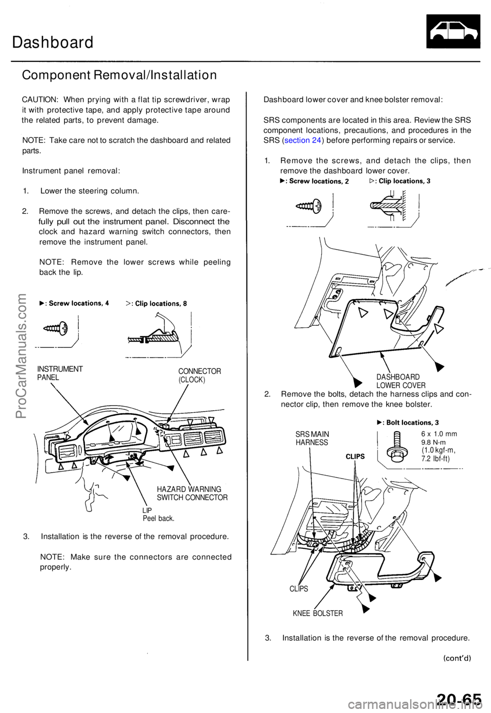
Dashboard
Componen t Removal/Installatio n
CAUTION: Whe n pryin g wit h a fla t ti p screwdriver , wra p
i t wit h protectiv e tape , an d appl y protectiv e tap e aroun d
th e relate d parts , t o preven t damage .
NOTE : Tak e car e no t t o scratc h th e dashboar d an d relate d
parts .
Instrumen t pane l removal :
1 . Lowe r th e steerin g column .
2 . Remov e th e screws , an d detac h th e clips , the n care -
fully pul l ou t th e instrumen t panel . Disconnec t th e
cloc k an d hazar d warnin g switc h connectors , the n
remov e th e instrumen t panel .
NOTE : Remov e th e lowe r screw s whil e peelin g
bac k th e lip .
INSTRUMEN TPANELCONNECTO R(CLOCK)
HAZARD WARNIN GSWITCH CONNECTO R
LIPPee l back .
3. Installatio n i s th e revers e o f th e remova l procedure .
NOTE : Mak e sur e th e connector s ar e connecte d
properly . Dashboar
d lowe r cove r an d kne e bolste r removal :
SR S component s ar e locate d in thi s area . Revie w th e SR S
componen t locations , precautions , an d procedure s i n th e
SR S (sectio n 24 ) befor e performin g repair s o r service .
1 . Remov e th e screws , an d detac h th e clips , the n
remov e th e dashboar d lowe r cover .
DASHBOAR DLOWER COVE R2. Remov e th e bolts , detac h th e harnes s clip s an d con -
necto r clip , the n remov e th e kne e bolster .
SRS MAI NHARNES S6 x 1. 0 m m9.8 N- m(1.0 kgf-m ,7.2 Ibf-ft )
KNEE BOLSTE R
3. Installatio n i s th e revers e o f th e remova l procedure .
CLIPS
ProCarManuals.com