Page 1432 of 1771

Front Sea t
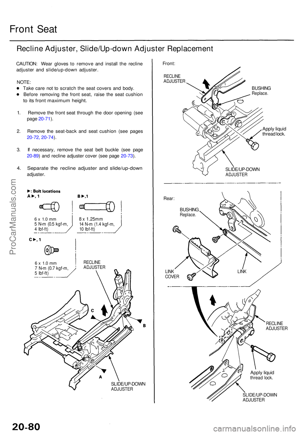
Reclin e Adjuster , Slide/Up-dow n Adjuste r Replacemen t
CAUTION: Wea r glove s t o remov e an d instal l th e reclin e
adjuste r an d slide/up-dow n adjuster .
NOTE :
Tak e car e no t t o scratc h th e sea t cover s an d body .
Befor e removin g th e fron t seat , rais e th e sea t cushio n
to it s fron t maximu m height .
1. Remov e th e fron t sea t throug h th e doo r openin g (se e
pag e 20-71 ).
2 . Remov e th e seat-bac k an d sea t cushio n (se e page s
20-72 , 20-74 ).
3 . I f necessary , remov e th e sea t bel t buckl e (se e pag e
20-89 ) an d reclin e adjuste r cove r (se e pag e 20-73 ).
4 . Separat e th e reclin e adjuste r an d slide/up-dow n
adjuster.
6 x 1. 0 m m5 N- m (0. 5 kgf-m ,4 Ibf-ft )
6 x 1. 0 m m7 N- m (0. 7 kgf-m ,5 Ibf-ft )
8 x 1.25m m14 N- m (1. 4 kgf-m ,10 Ibf-ft )
RECLIN EADJUSTE R
SLIDE/UP-DOW NADJUSTER
Front:
RECLIN EADJUSTE R
BUSHINGReplace .
Apply liqui d
threa d lock .
Rear :
BUSHIN GReplace .
LINKCOVE R
SLIDE/UP-DOW NADJUSTER
RECLINEADJUSTE R
Apply liqui dthrea d lock .
SLIDE/UP-DOW NADJUSTER
LINK
ProCarManuals.com
Page 1435 of 1771
Front Sea t
Reclin e Moto r Replacemen t
CAUTION: Wea r glove s t o remov e an d instal l th e reclin e
motor .
NOTE : Tak e car e no t t o scratc h th e sea t covers .
1 . Remov e th e fron t sea t throug h th e doo r openin g
(se e pag e 20-71 ).
2 . Remove :
Seat-bac k (se e pag e 20-72 )
Sea t cushio n (se e pag e 20-74 )
Reclin e adjuste r cove r (se e pag e 20-73 )
3 . Remov e th e reclin e motor .
5 x 0. 8 m m3 N- m (0. 3 kgf-m ,
2 1 Ibf-ft )
RECLIN E
MOTORApply liqui d threa dlock.RECLIN E
ADJUSTE R
4. Installatio n i s th e revers e o f th e remova l procedure .
NOTE:
Before installin g th e reclin e motor , appl y greas e
(molybdenu m grease ) t o th e gea r portion .
Replac e th e reclin e motor , bracket , pi n an d scre w
a s a n assembly .
Mak e sur e th e connecto r i s connecte d properly .
Chec k th e reclin e adjuste r operation .
RECLINEMOTOR
BRACKE T
PINSCRE W
ProCarManuals.com
Page 1436 of 1771

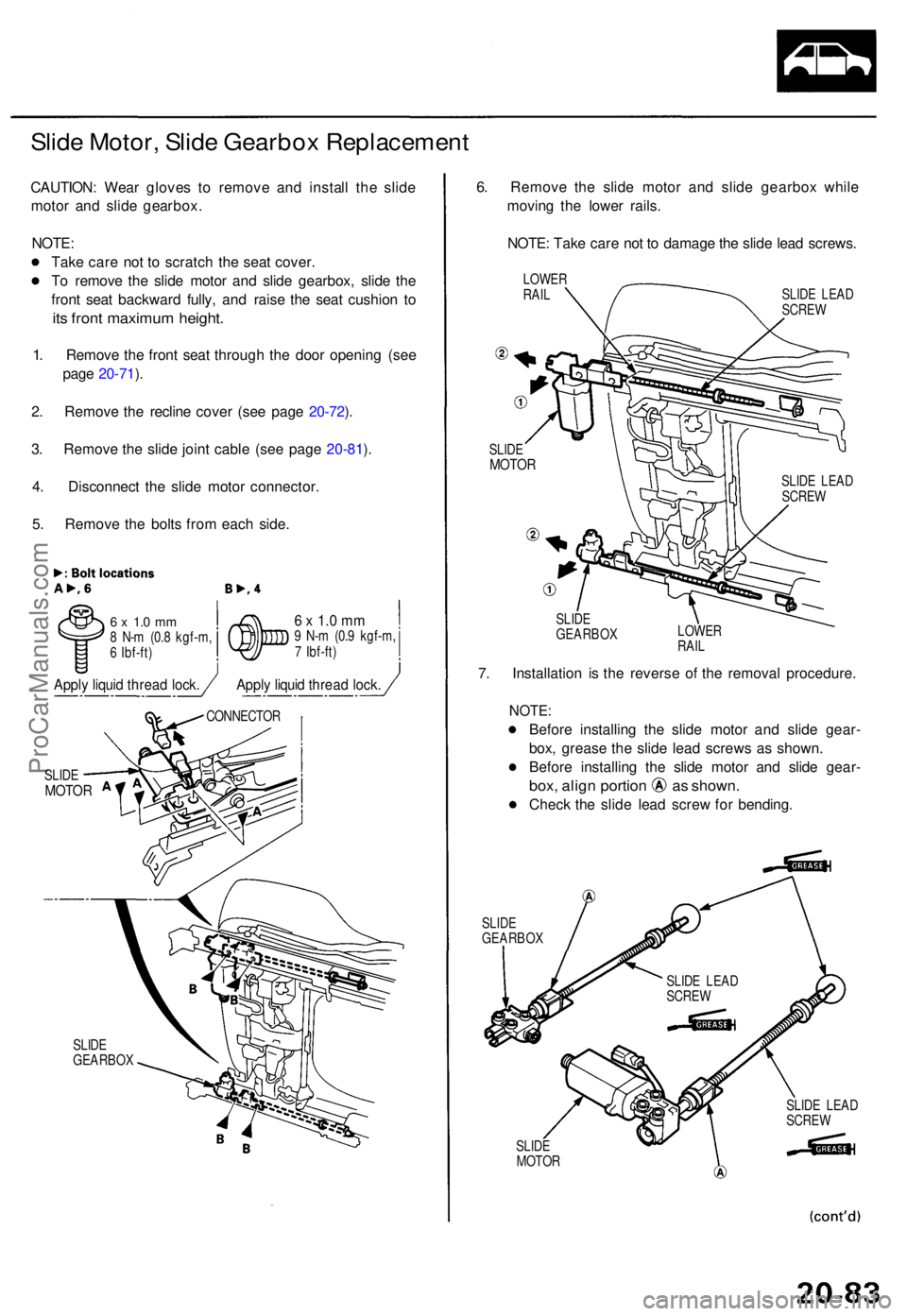
Slide Motor , Slid e Gearbo x Replacemen t
CAUTION: Wea r glove s t o remov e an d instal l th e slid e
moto r an d slid e gearbox .
NOTE :
Tak e car e no t t o scratc h th e sea t cover .
T o remov e th e slid e moto r an d slid e gearbox , slid e th e
fron t sea t backwar d fully , an d rais e th e sea t cushio n t o
its fron t maximu m height .
1. Remov e th e fron t sea t throug h th e doo r openin g (se e
pag e 20-71 ).
2 . Remov e th e reclin e cove r (se e pag e 20-72 ).
3 . Remov e th e slid e join t cabl e (se e pag e 20-81 ).
4 . Disconnec t th e slid e moto r connector .
5 . Remov e th e bolt s fro m eac h side .
6 x 1. 0 m m8 N- m (0. 8 kgf-m ,
6 Ibf-ft )6 x 1. 0 m m9 N- m (0. 9 kgf-m ,
7 Ibf-ft )
SLID E
GEARBO X
6. Remov e th e slid e moto r an d slid e gearbo x whil e
movin g th e lowe r rails .
NOTE : Tak e car e no t t o damag e th e slid e lea d screws .
LOWERRAILSLID E LEA D
SCRE W
SLID E
MOTO R
SLIDE
GEARBO X LOWE
R
RAIL
7. Installatio n i s th e revers e o f th e remova l procedure .
NOTE:
Before installin g th e slid e moto r an d slid e gear -
box , greas e th e slid e lea d screw s a s shown .
Befor e installin g th e slid e moto r an d slid e gear -
box, alig n portio n a s shown .
Check th e slid e lea d scre w fo r bending .
SLIDEGEARBO X
SLIDE
MOTO R SLID
E LEA D
SCRE W
SLID E
MOTO R
CONNECTO R
SLIDE LEA D
SCRE W
SLIDE LEA D
SCRE W
Apply liqui d threa d lock .Apply liqui d threa d lock .
ProCarManuals.com
Page 1438 of 1771
Front Sea t
Front an d Rea r Up-dow n Motor s
Replacemen t
CAUTION: Wea r glove s t o remov e an d instal l th e fron t
an d rea r up-dow n motors .
NOTE:
• Tak e car e no t t o scratc h th e sea t covers .
• Befor e removin g th e fron t seat , rais e th e sea t cushio n
to it s maximu m height .
1. Remov e th e fron t sea t throug h th e doo r openin g
(see pag e 20-71 ).
2 . Remov e th e sea t cushio n (se e pag e 20-74 ).
3 . Fro m unde r th e sea t linkage , disconnec t th e fron t an d
rea r up-dow n moto r connectors , an d remov e th e
bolts .
REA R UP-DOW NMOTORFRONT UP-DOW NMOTOR
CONNECTO R
Bolt locations , 2
6 x 1. 0 m m5 N- m (0. 5 kgf-m ,4 Ibf-ft )
Apply liqui d threa d lock .
ProCarManuals.com
Page 1444 of 1771

Seat Belt
Inspection
Retractor Inspection
1. Before installing the retractor, check that the seat belt
can be pulled out freely.
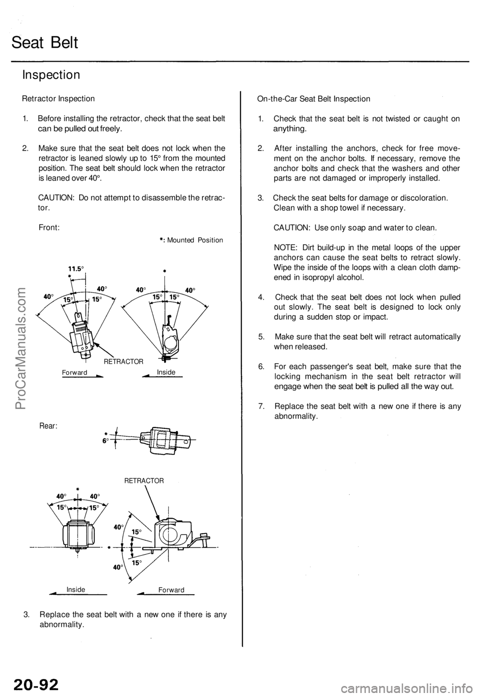
2. Make sure that the seat belt does not lock when the
retractor is leaned slowly up to 15° from the mounted
position. The seat belt should lock when the retractor
is leaned over 40°.
CAUTION: Do not attempt to disassemble the retrac-
tor.
Front:
Mounted Position
Rear:
RETRACTOR
Inside
Forward
3. Replace the seat belt with a new one if there is any
abnormality.
On-the-Car Seat Belt Inspection
1. Check that the seat belt is not twisted or caught on
anything.
2. After installing the anchors, check for free move-
ment on the anchor bolts. If necessary, remove the
anchor bolts and check that the washers and other
parts are not damaged or improperly installed.
3. Check the seat belts for damage or discoloration.
Clean with a shop towel if necessary.
CAUTION: Use only soap and water to clean.
NOTE: Dirt build-up in the metal loops of the upper
anchors can cause the seat belts to retract slowly.
Wipe the inside of the loops with a clean cloth damp-
ened in isopropyl alcohol.
4. Check that the seat belt does not lock when pulled
out slowly. The seat belt is designed to lock only
during a sudden stop or impact.
5. Make sure that the seat belt will retract automatically
when released.
6. For each passenger's seat belt, make sure that the
locking mechanism in the seat belt retractor will
engage when the seat belt is pulled all the way out.
7. Replace the seat belt with a new one if there is any
abnormality.
RETRACTOR
Forward
InsideProCarManuals.com
Page 1451 of 1771

Hood
Replacemen t
NOTE:
An assistan t i s helpfu l whe n removin g th e hood .
Tak e car e no t t o damag e th e hoo d an d body .
Whe n removin g th e clips , us e a cli p remover .
Ope n th e hood .
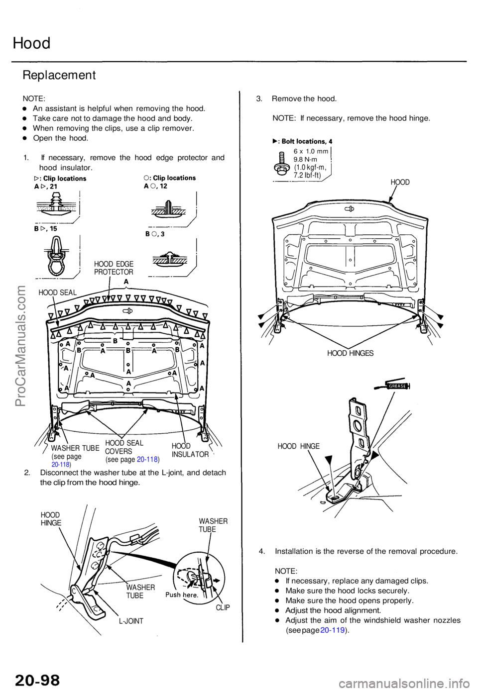
1 . I f necessary , remov e th e hoo d edg e protecto r an d
hoo d insulator .
HOOD EDG EPROTECTO R
HOOD SEA L
HOOD SEA L
COVER S
(se e pag e 20-118 )HOO
D
INSULATO R
WASHE
R TUB E
(se e pag e
20-118 )2. Disconnec t th e washe r tub e a t th e L-joint , an d detac h
the cli p fro m th e hoo d hinge .
HOODHING EWASHE R
TUB E
CLIP
3. Remov e th e hood .
NOTE : I f necessary , remov e th e hoo d hinge .
6 x 1. 0 m m9.8 N- m(1.0 kgf-m ,
7. 2 Ibf-ft )
HOOD
HOOD HINGE S
HOOD HING E
4. Installatio n is th e revers e o f th e remova l procedure .
NOTE:
If necessary , replac e an y damage d clips .
Mak e sur e th e hoo d lock s securely .
Mak e sur e th e hoo d open s properly .
Adjust th e hoo d alignment .
Adjust th e ai m o f th e windshiel d washe r nozzle s
(se e pag e 20-119 ).L-JOIN T
WASHE RTUBE
ProCarManuals.com
Page 1454 of 1771
c. Remov e th e bolts , the n remov e th e trun k li d
hinge .
6 x 1. 0 m m9.8 N- m (1. 0 kgf-m ,7.2 Ibf-ft )
NOTE: Tak e car e no t
t o hi t th e rea r windo w
when removin g th e bolt s
TRUN K LI D
HING E
5. Installatio n is th e revers e o f th e remova l procedure .
NOTE:
Make sur e th e connector s ar e connecte d properly .
Adjus t th e torsio n bar s for e o r af t wit h th e tor -
sio n ba r assembl y too l a s shown .
Mak e sur e th e trun k li d lock s securely .
Mak e sur e th e trun k li d open s properly .
Adjus t th e trun k li d alignmen t (se e pag e 20-102 ).
ProCarManuals.com
Page 1468 of 1771
Opener an d Latc h
Replacemen t
NOTE: Tak e car e no t t o ben d th e opene r cables .
Hoo d releas e handle :
HOOD OPENE RCABLE(see pag e 20-113 )
HOO D RELEAS E
HANDL E
Remov e th e lef t kic k
pane l (se e pag e
20-63 ).
Hoo d latch :
NOTE : I f necessary , remov e th e cover .
6 x 1. 0 m m9.8 N- m(1.0 kgf-m ,
7. 2 Ibf-ft )
HOO D LATC H
Remov e th e fron t
grill e (se e pag e
20-104 ).
HOO D OPENE R
CABLE
COVE R
Installatio n i s th e revers e o f th e remova l procedure .
NOTE:
Make sur e th e opene r cabl e i s connecte d properly .
Mak e sur e th e hoo d lock s securely .
Mak e sur e th e hoo d open s properly .
6 x 1. 0 m m9.8 N- m(1.0 kgf-m ,
7. 2 Ibf-ft )
NOTE : Refe r t o page 20-11a of th e '96-9 8 Acura 3.2TL Service Manual supplement forfor the differences on this page for the 3.2TL.
ProCarManuals.com