Page 1537 of 1771

Troubleshooting
Tips and Precautions (cont'd)
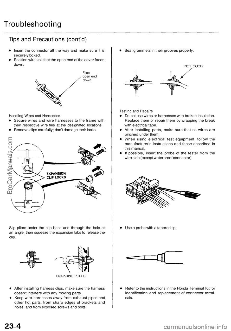
Insert the connector all the way and make sure it is
securely locked.
Position wires so that the open end of the cover faces
down.
Face
open end
down
Handling Wires and Harnesses
Secure wires and wire harnesses to the frame with
their respective wire ties at the designated locations.
Remove clips carefully; don't damage their locks.
Slip pliers under the clip base and through the hole at
an angle, then squeeze the expansion tabs to release the
clip.
SNAP-RING PLIERS
After installing harness clips, make sure the harness
doesn't interfere with any moving parts.
Keep wire harnesses away from exhaust pipes and
other hot parts, from sharp edges of brackets and
holes, and from exposed screws and bolts.
Seat grommets in their grooves properly.
NOT GOOD
Testing and Repairs
Do not use wires or harnesses with broken insulation.
Replace them or repair them by wrapping the break
with electrical tape.
After installing parts, make sure that no wires are
pinched under them.
When using electrical test equipment, follow the
manufacturer's instructions and those described in
this manual.
If possible, insert the probe of the tester from the
wire side (except waterproof connector).
Use a probe with a tapered tip.
Refer to the instructions in the Honda Terminal Kit for
identification and replacement of connector termi-
nals.ProCarManuals.com
Page 1543 of 1771
CLIMATE CONTROL UNIT
RADIATOR
FAN CONTROL
MODULE
ABS CONTROL UNIT
('95 -97 models)
KEYLESS DOOR LOCK CONTROL
UNIT ('98 model)
SECURITY CONTROL
UNIT
ABS CONTROL UNIT
('98 model)
MOONROOF OPEN RELAY
Wire colors: GRY, GRN/YEL,
GRN,
YEL and BLK
MOONROOF CLOSE RELAY
Wire colors: GRY/RED, GRN/RED,
GRN,
YEL and BLK
TRANSMISSION
CONTROL
MODULE (TCM)ProCarManuals.com
Page 1544 of 1771
Relay and Control Unit Locations
Door
POWER WINDOW MASTER SWITCH
(Has built-in control unit)
POWER DOOR LOCK
CONTROL UNITProCarManuals.com
Page 1553 of 1771
Ignition Switch
Steering Lock Replacement (cont'd)
6. Remove the column holder mounting bolts and nuts.
16 N-m
(1.6 kgf-m, 12 Ibf-ft)
COLUMN
HOLDER
38 N-m
(3.9 kgf-m, 28 Ibf-ft)
7. Lower the steering column assembly.
8. Center-punch each of the two shear bolts, and drill
their heads off with a 5 mm (3/16 in) drill bit.
CAUTION: Do not damage the switch body when
removing the shear bolts.
9. Remove the shear bolts from the switch body, then
remove the steering lock assembly.
Installation:
1. Install the new ignition switch without the key
inserted.
2. Loosely tighten the new shear bolts.
3. Insert the ignition key, and check for proper opera-
tion of the steering wheel lock and that the ignition
key turns freely.
4. Tighten the shear bolts until the hex heads twist off.
SHEAR BOLT
TWIST-OFF PORTION
5. Install in the reverse order of removal.
6. Enter the anti-theft code for the radio, then enter the
customer's radio station presets.ProCarManuals.com
Page 1564 of 1771

Overrunning Clutc h Inspectio n
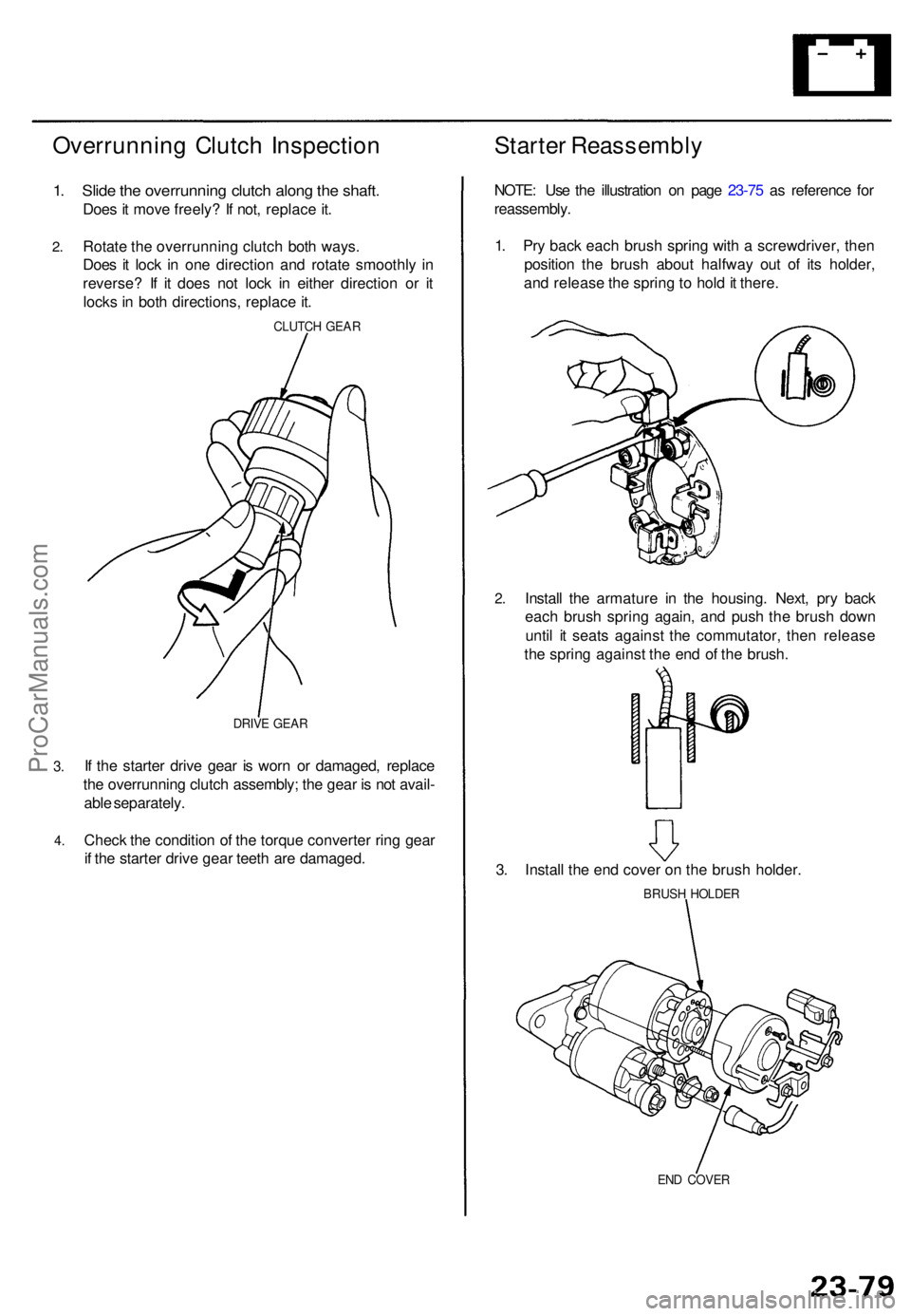
1. Slid e th e overrunnin g clutc h alon g th e shaft .
Does i t mov e freely ? I f not , replac e it .
Starte r Reassembl y
2.Rotat e th e overrunnin g clutc h bot h ways .
Doe s i t loc k i n on e directio n an d rotat e smoothly in
reverse ? I f i t doe s no t loc k i n eithe r directio n o r i t
lock s in bot h directions , replac e it .
CLUTC H GEA R
3.
4 .
DRIV E GEA R
If th e starte r driv e gea r i s wor n o r damaged , replac e
th e overrunnin g clutc h assembly ; th e gea r i s no t avail -
abl e separately .
Chec k th e conditio n o f th e torqu e converte r rin g gea r
i f th e starte r driv e gea r teet h ar e damaged . NOTE
: Us e th e illustratio n o n pag e 23-7 5 a s referenc e fo r
reassembly .
1 . Pr y bac k eac h brus h sprin g wit h a screwdriver , the n
positio n th e brus h abou t halfwa y ou t o f it s holder ,
an d releas e th e sprin g t o hol d it there .
2.Instal l th e armatur e i n th e housing . Next , pr y bac k
eac h brus h sprin g again , an d pus h th e brus h dow n
unti l i t seat s agains t th e commutator , the n releas e
th e sprin g agains t th e en d o f th e brush .
3 . Instal l th e en d cove r o n th e brus h holder .
BRUSH HOLDE R
END COVE R
ProCarManuals.com
Page 1584 of 1771
Alternator Overhau l
NOTE: D o no t remov e th e pulle y unles s th e fron t bear -
in g need s replacement .
T o loose n th e pulle y locknut , us e th e tool s a s shown . I f
necessary , us e a n impac t wrench .
END COVE R
TERMINA L INSULATO R
BRUSH HOLDE RINSULATO R
BRUSH ASSEMBL Y
Inspection , pag e 23-10 2
VOLTAG E
REGULATO R
SPACER RIN G
REA R BEARIN G PULLE
Y
22 m m BO XWRENC H
10 m m BO X WRENC H
PULLEY LOCKNU T
11 1 N- m (11. 3 kgf-m , 81. 7 Ibf-ft )
RECTIFIE R ASSEMBL Y
Test , pag e 23-10 2
REAR HOUSIN G
Do no tdisassemble .
BEARING INSULATO R
STATOR THROUGH-BOL T
STATOR ASSEMBLY/DRIV E EN D HOUSIN G
Test , pag e 23-10 3
PULLE Y LOCKNU T
11 1 N- m (11. 3 kgf-m , 81. 7 Ibf-ft )
CAUTION : D o no t ge t greas e
or oi l o n th e sli p rings .
FRONT BEARIN G
PULLEY
ROTO
R
Test , pag e 23-10 3 INSULATO
R SLEEV E
ProCarManuals.com
Page 1585 of 1771

Charging System
Rectifier Test
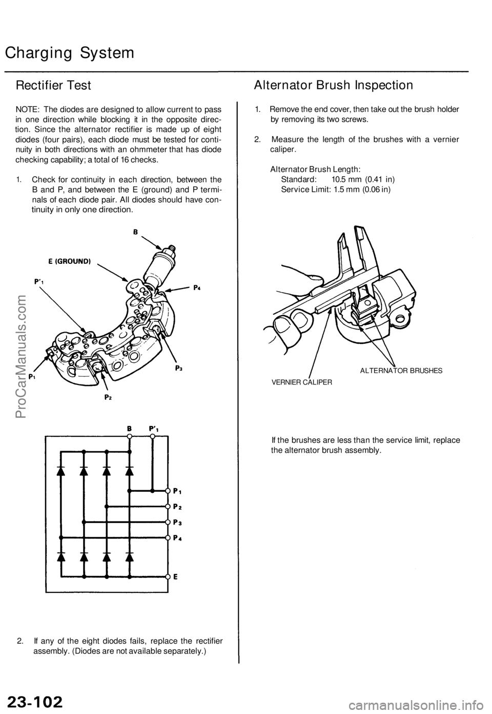
NOTE: The diodes are designed to allow current to pass
in one direction while blocking it in the opposite direc-
tion. Since the alternator rectifier is made up of eight
diodes (four pairs), each diode must be tested for conti-
nuity in both directions with an ohmmeter that has diode
checking capability; a total of 16 checks.
1.
Check for continuity in each direction, between the
B and P, and between the E (ground) and P termi-
nals of each diode pair. All diodes should have con-
tinuity in only one direction.
2. If any of the eight diodes fails, replace the rectifier
assembly. (Diodes are not available separately.)
Alternator Brush Inspection
1. Remove the end cover, then take out the brush holder
by removing its two screws.
2. Measure the length of the brushes with a vernier
caliper.
Alternator Brush Length:
Standard: 10.5 mm (0.41 in)
Service Limit: 1.5 mm (0.06 in)
ALTERNATOR BRUSHES
VERNIER CALIPER
If the brushes are less than the service limit, replace
the alternator brush assembly.ProCarManuals.com
Page 1599 of 1771

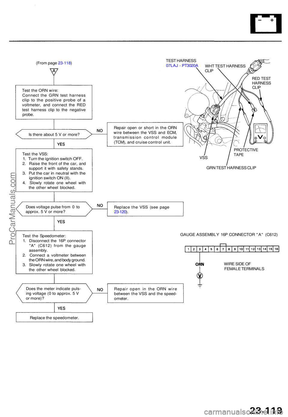
(From pag e 23-118 ) TES
T HARNES S
07LA J - PT3020 A
Tes t th e OR N wire :
Connec t th e GR N tes t harnes s
clip t o th e positiv e prob e o f avoltmeter , an d connec t th e RE D
tes t harnes s cli p t o th e negativ e
probe .
I s ther e abou t 5 V or more ? Repai
r ope n o r shor t i n th e OR N
wir e betwee n th e VS S an d ECM ,
transmissio n contro l modul e
(TCM) , an d cruis e contro l unit .
Tes t th e VSS :
1. Tur n th e ignitio n switc h OFF .2. Rais e th e fron t o f th e car , an d
suppor t i t wit h safet y stands .
3. Pu t th e ca r i n neutra l wit h th eignitio n switc h O N (II) .4. Slowl y rotat e on e whee l wit h
th e othe r whee l blocked .
VSS
GR N TES T HARNES S CLI P
Doe s voltag e puls e fro m 0 to
approx . 5 V or more ? Replac
e th e VS S (se e pag e
23-120 ).
Tes t th e Speedometer :
1 . Disconnec t th e 16 P connecto r
"A " (C612 ) fro m th e gaug e
assembly .
2 . Connec t a voltmete r betwee n
the OR N wire , an d bod y ground .3. Slowl y rotat e on e whee l wit hthe othe r whee l blocked . GAUG
E ASSEMBL Y 16 P CONNECTO R "A " (C612 )
WIR E SID E O F
FEMAL E TERMINAL S
Doe s th e mete r indicat e puls -
in g voltag e ( 0 to approx . 5 V
o r more) ? Repai
r ope n i n th e OR N wir e
betwee n th e VS S an d th e speed -
ometer .
Replac e th e speedometer .
PROTECTIVETAPE
RED TES THARNES SCLIP
WH T TES T HARNES SCLIP
ProCarManuals.com