Page 1725 of 1771

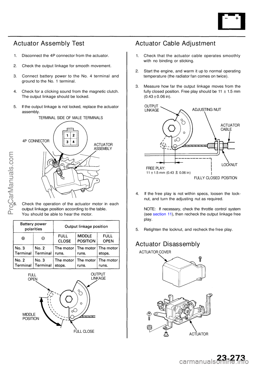
Actuator Assembl y Tes t
1. Disconnec t th e 4 P connecto r fro m th e actuator .
2 . Chec k th e outpu t linkag e fo r smoot h movement .
3 . Connec t batter y powe r t o th e No . 4 termina l an d
groun d t o th e No . 1 terminal .
4 . Chec k fo r a clickin g soun d fro m th e magneti c clutch .
Th e outpu t linkag e shoul d b e locked .
5 . I f th e outpu t linkag e is no t locked , replac e th e actuato r
assembly .
TERMINA L SID E O F MAL E TERMINAL S
4 P CONNECTO R
ACTUATOR
ASSEMBL Y
6. Chec k th e operatio n o f th e actuato r moto r i n eac h
outpu t linkag e positio n accordin g to th e table .
You shoul d b e abl e t o hea r th e motor .
OUTPU TLINKAG E
MIDDLEPOSITIO N
FULL CLOS E
Actuato r Cabl e Adjustmen t
1. Chec k tha t th e actuato r cabl e operate s smoothl y
wit h n o bindin g o r sticking .
2 . Star t th e engine , an d war m it u p to norma l operatin g
temperatur e (th e radiato r fa n come s o n twice) .
3 . Measur e ho w fa r th e outpu t linkag e move s fro m th e
full y close d position . Fre e pla y shoul d b e 1 1 ± 1. 5 m m
(0.4 3 ± 0.0 6 in) .
OUTPU T
LINKAG EADJUSTIN G NU T
ACTUATO RCABLE
4. I f th e fre e pla y i s no t withi n specs , loose n th e lock -
nut , an d tur n th e adjustin g nu t a s required .
NOTE : I f necessary , chec k th e throttl e contro l syste m
(se e sectio n 11 ), the n rechec k th e outpu t linkag e fre e
play .
5. Retighte n th e locknut , an d rechec k th e fre e play .
Actuato r Disassembl y
ACTUATOR COVE R
ACTUATO R
FULL
OPE N FULL
Y CLOSE D POSITIO N
LOCKNU
T
FRE E PLAY :
11 ± 1. 5 m m (0.4 3 ± 0.06 in)
ProCarManuals.com
Page 1728 of 1771

Security Alar m Syste m
Descriptio n
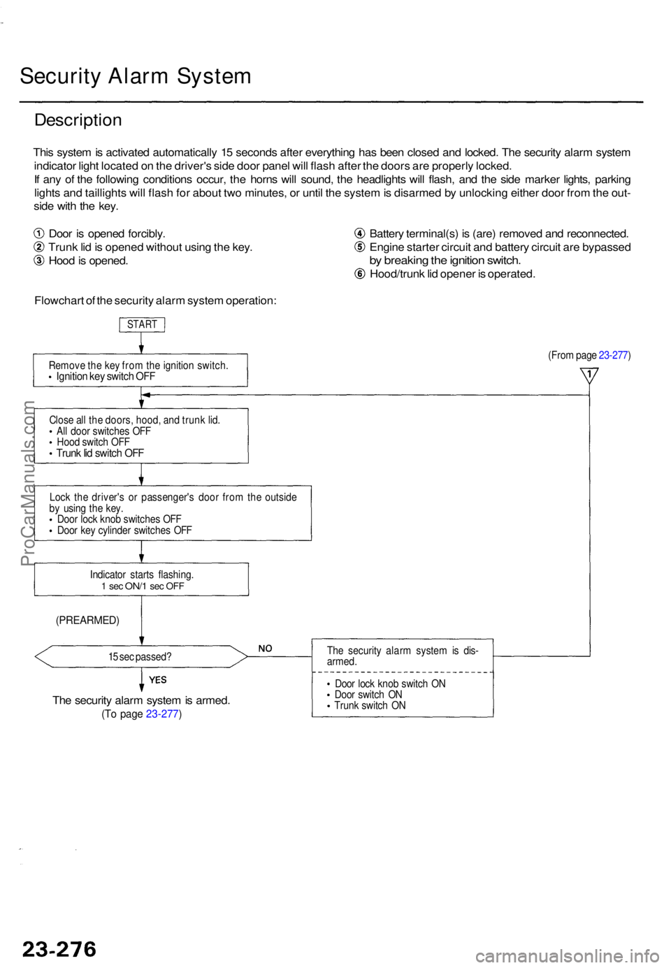
This syste m is activate d automaticall y 1 5 second s afte r everythin g ha s bee n close d an d locked . Th e securit y alar m syste m
indicato r ligh t locate d o n th e driver' s sid e doo r pane l wil l flas h afte r th e door s ar e properl y locked .
I f an y o f th e followin g condition s occur , th e horn s wil l sound , th e headlight s wil l flash , an d th e sid e marke r lights , parkin g
light s an d taillight s wil l flas h fo r abou t tw o minutes , o r unti l th e syste m is disarme d b y unlockin g eithe r doo r fro m th e out -
sid e wit h th e key .
Doo r i s opene d forcibly .
Trun k li d is opene d withou t usin g th e key .
Hoo d is opened . Batter
y terminal(s ) i s (are ) remove d an d reconnected .
Engin e starte r circui t an d batter y circui t ar e bypasse d
by breakin g th e ignitio n switch .
Hood/trun k li d opene r i s operated .
Flowchar t o f th e securit y alar m syste m operation :
START
Remov e th e ke y fro m th e ignitio n switch .Ignition ke y switc h OF F
(Fro m pag e 23-277 )
Clos e al l th e doors , hood , an d trun k lid .
Al l doo r switche s OF F
Hoo d switc h OF F
Trun k li d switc h OF F
Loc k th e driver' s o r passenger' s doo r fro m th e outsid e
b y usin g th e key .
Doo r loc k kno b switche s OF F
Doo r ke y cylinde r switche s OF F
Indicato r start s flashing .
1 se c ON/ 1 sec OF F
(PREARMED )
15 se c passed ?
The securit y alar m syste m is armed .
(To pag e 23-277 )
The securit y alar m syste m is dis -
armed .
Doo r loc k kno b switc h O N
Doo r switc h O N
Trun k switc h O N
ProCarManuals.com
Page 1729 of 1771

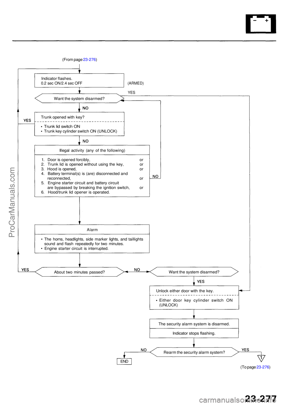
(From pag e 23-276 )
Indicato r flashes .
0.2 se c ON/2. 4 se c OF F
Wan t th e syste m disarmed ?
(ARMED)
YES
Trun k opene d wit h key ?
Trun k li d switc h O NTrun k ke y cylinde r switc h O N (UNLOCK )
Illega l activit y (an y o f th e following )
1 . Doo r i s opene d forcibly , o r
2 . Trun k li d i s opene d withou t usin g th e key , o r
3 . Hoo d is opened , o r
4 . Batter y terminal(s ) i s (are ) disconnecte d an d
reconnected , o r
5 . Engin e starte r circui t an d batter y circui t
ar e bypasse d b y breakin g th e ignitio n switch , o r
6 . Hood/trun k li d opene r i s operated .
Alarm
The horns , headlights , sid e marke r lights , an d taillight s
soun d an d flas h repeatedl y fo r tw o minutes .
Engin e starte r circui t i s interrupted .
Abou t tw o minute s passed ? Wan
t th e syste m disarmed ?
Unloc k eithe r doo r wit h th e key .
Eithe r doo r ke y cylinde r switc h O N
(UNLOCK )
The securit y alar m syste m is disarmed.
Indicato r stop s flashing .
Rearm th e securit y alar m system ?
(To pag e 23-276 )
END
ProCarManuals.com
Page 1735 of 1771
Security Trunk Latch Switch Test
1. Open the trunk lid.
2. Disconnect the 2P connector from the security trunk
latch switch.
3. Check for continuity between the terminals in each
switch position according to the table.
TRUNK LATCH
SWITCH
2P
CONNECTOR
LOCK
TERMINAL SIDE OF MALE TERMINALS
4. Be sure to unlock the trunk latch after testing the
switch.
Security Trunk Key Cylinder
Switch Test
1. Open the trunk lid.
2. Disconnect the 2P connector from the security trunk
key cylinder switch.
3. Check for continuity between the terminals in each
switch position according to the table.
UNLOCK
TRUNK KEY
CYLINDER
REED SWITCH
2P CONNECTOR
TERMINAL SIDE OF MALE TERMINALSProCarManuals.com
Page 1742 of 1771
Wiring Precaution s
• Neve r attemp t t o modify , splic e o r repai r SR S wiring .
NOTE : SR S wirin g ca n b e identifie d b y specia l yello w
oute r covering .
• B e sur e to instal l th e harnes s wire s s o tha t the y ar e no t
pinche d o r interferin g wit h othe r parts .
• Mak e sur e al l SR S groun d location s ar e clea n an d
ground s ar e securel y fastene d fo r optimu m metal-to -
meta l contact . Poo r groundin g ca n caus e intermitten t
problem s tha t ar e difficul t t o diagnose . Disconnectin
g th e SR S Connecto r a t th e Under-das h
Fuse/Relay Box :
CAUTION : Avoi d breakin g th e connector ; it' s double -
locked.
1. Firs t lif t th e connecto r li d wit h a thi n screwdriver , the n
pres s th e connecto r ta b down , an d pul l th e connecto r
out.
2. T o reinstal l th e connector , pus h it int o positio n unti l i t
clicks , the n clos e it s lid .
ProCarManuals.com
Page 1743 of 1771
Precautions/Procedures
Spring-loaded Loc k Connecto r
Some SR S syste m connector s hav e a spring-loade d
lock .
Disconnectin g
T o releas e th e lock , pul l th e spring-loade d sleev e towar d
th e sto p whil e holdin g th e opposit e hal f o f th e connector .
The n pul l th e connecto r halve s apart .
NOTE : B e sur e t o pul l o n th e sleev e an d no t o n th e con -
necto r hal f itself . Connectin
g
Hol d th e pawl-sid e connecto r half , an d pres s o n th e
bac k o f th e sleeve-sid e connecto r hal f i n th e directio n
shown . A s th e tw o connecto r halve s ar e presse d
together , th e sleev e is pushe d bac k b y th e pawl .
NOTE : D o no t touc h th e sleeve .
2 . Whe n th e connecto r halve s ar e completel y connected ,
th e paw l i s released , an d th e spring-loade d sleev e
lock s th e connector .
ProCarManuals.com
Page 1744 of 1771
Spring-loaded Loc k Connecto r wit h
Built-i n Shor t Contac t
The driver' s airba g ('95-9 8 models ) an d fron t passen -
ger' s airba g ('97-9 8 models ) hav e a spring-loade d loc k
connecto r wit h a built-i n shor t contact . Whe n thi s con -
necto r i s disconnected , th e powe r termina l an d th e
groun d termina l i n th e airba g connecto r ar e automati -
call y shorted .
Backprobin g Spring-loade d Loc k
Connector s
• Whe n checkin g voltag e o r resistanc e o n thi s typ e o f
connecto r th e firs t time , i t i s necessar y t o remov e th e
retaine r t o inser t teste r probe s fro m th e wir e side . I t
i s no t necessar y t o reinstal l th e remove d retainer ; th e
terminal s wil l sta y locke d in th e connecto r housing .
• T o remov e th e retainer , inser t a fla t ti p screwdrive r
betwee n connecto r bod y an d retainer , an d carefull y
pr y ou t th e retainer . Tak e car e no t t o brea k th e con -
nector .
ProCarManuals.com
Page 1746 of 1771

Steering-related Precautions
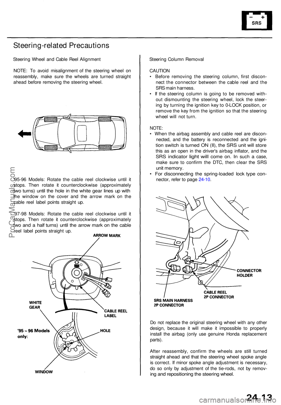
Steering Whee l an d Cabl e Ree l Alignmen t
NOTE : T o avoi d misalignmen t o f th e steerin g whee l o n
reassembly , mak e sur e th e wheel s ar e turne d straigh t
ahea d befor e removin g th e steerin g wheel .
'95-9 6 Models : Rotat e th e cabl e ree l clockwis e unti l i t
stops . The n rotat e i t counterclockwis e (approximatel y
two turns ) unti l th e hol e in th e whit e gea r line s u p wit h
the windo w o n th e cove r an d th e arro w mar k o n th e
cabl e ree l labe l point s straigh t up .
'97-9 8 Models : Rotat e th e cabl e ree l clockwis e unti l i t
stops . The n rotat e i t counterclockwis e (approximatel y
two an d a hal f turns ) unti l th e arro w mar k o n th e cabl e
reel labe l point s straigh t up . Steerin
g Colum n Remova l
CAUTIO N
• Befor e removin g th e steerin g column , firs t discon -
nec t th e connecto r betwee n th e cabl e ree l an d th e
SR S mai n harness .
• I f th e steerin g colum n i s goin g t o b e remove d with -
ou t dismountin g th e steerin g wheel , loc k th e steer -
in g b y turnin g th e ignitio n ke y to 0-LOC K position , o r
remov e th e ke y fro m th e ignitio n s o tha t th e steerin g
whee l wil l no t turn .
NOTE :
• Whe n th e airba g assembl y an d cabl e ree l ar e discon -
nected , an d th e batter y i s reconnecte d an d th e igni -
tion switc h is turne d O N (II) , th e SR S uni t wil l stor e
this a s a n ope n i n th e driver' s airba g inflator , an d th e
SR S indicato r light will com e on. I n suc h a case ,
mak e sur e t o confir m th e DTC , the n clea r th e SR S
unit memory .
• Fo r disconnectin g th e spring-loade d loc k typ e con -
nector , refe r t o pag e 24-10 .
D o no t replac e th e origina l steerin g whee l wit h an y othe r
design , becaus e i t wil l mak e i t impossibl e t o properly
instal l th e airba g (onl y us e genuin e Hond a replacemen t
parts) .
Afte r reassembly , confir m th e wheel s ar e stil l turne d
straight ahea d an d tha t th e steerin g whee l spok e angl e
is correct . I f mino r spok e angl e adjustment is necessary ,
d o s o onl y b y adjustmen t o f th e tie-rods , no t b y remov -
ing an d repositionin g th e steerin g wheel .
ProCarManuals.com