Page 1606 of 1771
Interlock Syste m
Componen t Locatio n Inde x
SRS component s ar e locate d in thi s area . Revie w th e SR S componen t locations , precautions , an d procedure s in th e SR S
(sectio n 24 ) befor e performin g repair s o r service .
A/T GEA R POSITIO N INDICATO R
Se e pag e 23-11 5
A/ T GEA R POSITIO N SWITC H
Test , pag e 23-14 6
INTERLOC KCONTROLUNITInpu t Test , pag e 23-13 0 KE
Y INTERLOC K SOLENOI D
an d KE Y INTERLOC K SWITC H
(I n th e steerin g loc k assembly )
Test , pag e 23-13 2
SHIF T LOC K SOLENOI D
Test , pag e 23-13 2
Replacement , pag e 23-13 3
PARKING PI N SWITC H
Test , pag e 23-13 4
Replacement , pag e 23-13 4
ProCarManuals.com
Page 1607 of 1771

Description
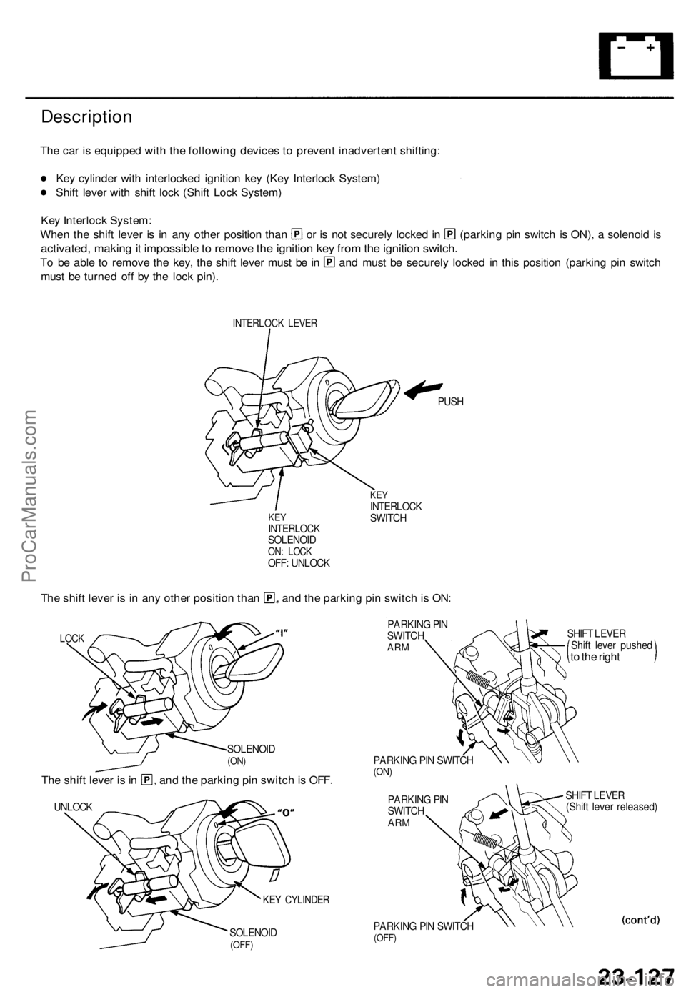
The car is equipped with the following devices to prevent inadvertent shifting:
Key cylinder with interlocked ignition key (Key Interlock System)
Shift lever with shift lock (Shift Lock System)
Key Interlock System:
When the shift lever is in any other position than or is not securely locked in (parking pin switch is ON), a solenoid is
activated, making it impossible to remove the ignition key from the ignition switch.
To be able to remove the key, the shift lever must be in and must be securely locked in this position (parking pin switch
must be turned off by the lock pin).
INTERLOCK LEVER
KEY
INTERLOCK
SOLENOID
ON: LOCK
OFF: UNLOCK
PUSH
KEY
INTERLOCK
SWITCH
The shift lever is in any other position than , and the parking pin switch is ON:
LOCK
SOLENOID
(ON)
The shift lever is in , and the parking pin switch is OFF.
UNLOCK
SOLENOID
(OFF)
PARKING PIN
SWITCH
ARM
PARKING PIN SWITCH
(ON)
PARKING PIN
SWITCH
ARM
PARKING PIN SWITCH
(OFF)
SHIFT LEVER
Shift lever pushed
to the right
SHIFT LEVER
(Shift lever released)
KEY CYLINDERProCarManuals.com
Page 1608 of 1771
Interlock System
Description (cont'd)
Shift Lock System:
The shift lock system prevents the shift lever from moving to another position than [P] unless you step on the brake pedal
and the accelerator is in its rest position.
NOTE:
The shift lever cannot be shifted when the brake pedal and the accelerator are depressed at the same time.
In case of system malfunction, the shift lever can be released by pushing a key into the release slot near the shift lever.
SHIFT LEVER
SHIFT LEVER
SHIFT LOCK SOLENOID
(OFF: LOCK)
SHIFT LOCK SOLENOID
(ON: UNLOCK)
SHIFT LOCK STOP LEVER
SHIFT LOCK STOP LEVER
KEY
RELEASE LEVER
SHIFT LOCK STOP LEVERProCarManuals.com
Page 1609 of 1771

Interlock Syste m
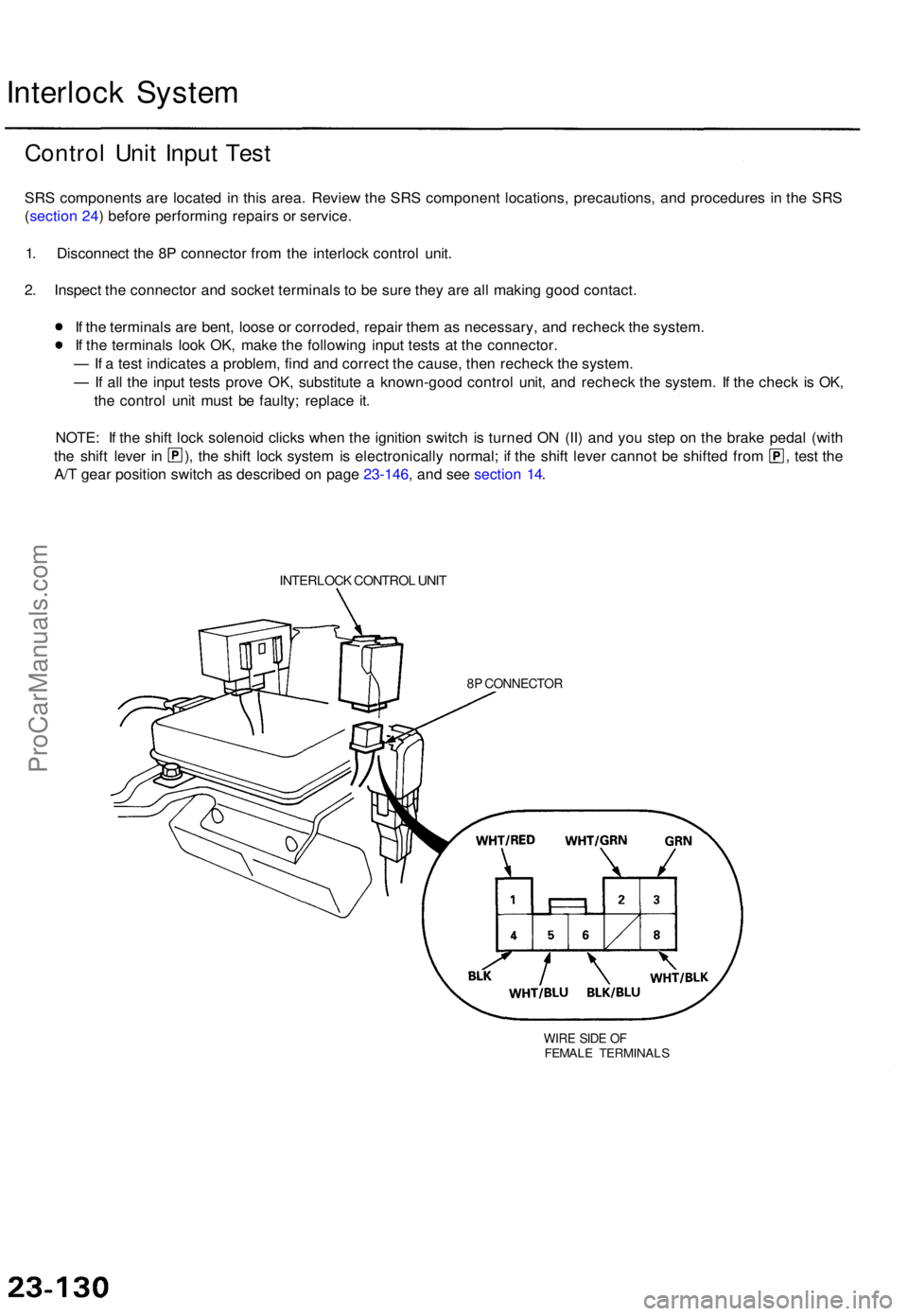
Contro l Uni t Inpu t Tes t
SRS component s ar e locate d i n thi s area . Revie w th e SR S componen t locations , precautions , an d procedure s i n th e SR S
( sectio n 24 ) befor e performin g repair s o r service .
1 . Disconnec t th e 8 P connecto r fro m th e interloc k contro l unit .
2 . Inspec t th e connecto r an d socke t terminal s t o b e sur e the y ar e al l makin g goo d contact .
I f th e terminal s ar e bent , loos e o r corroded , repai r the m a s necessary , an d rechec k th e system .
I f th e terminal s loo k OK , mak e th e followin g inpu t test s a t th e connector .
— If a tes t indicate s a problem , fin d an d correc t th e cause , the n rechec k th e system .
— If al l th e inpu t test s prov e OK , substitut e a known-goo d contro l unit , an d rechec k th e system . I f th e chec k i s OK ,
th e contro l uni t mus t b e faulty ; replac e it .
NOTE : I f th e shif t loc k solenoi d click s whe n th e ignitio n switc h i s turne d O N (II ) an d yo u ste p o n th e brak e peda l (wit h
the shif t leve r i n ) , th e shif t loc k syste m is electronicall y normal ; i f th e shif t leve r canno t b e shifte d fro m , test th e
A/ T gea r positio n switc h a s describe d o n pag e 23-146 , an d se e sectio n 14 .
INTERLOC K CONTRO L UNI T
8P CONNECTO R
WIRE SID E O FFEMAL E TERMINAL S
ProCarManuals.com
Page 1611 of 1771

Interlock Syste m
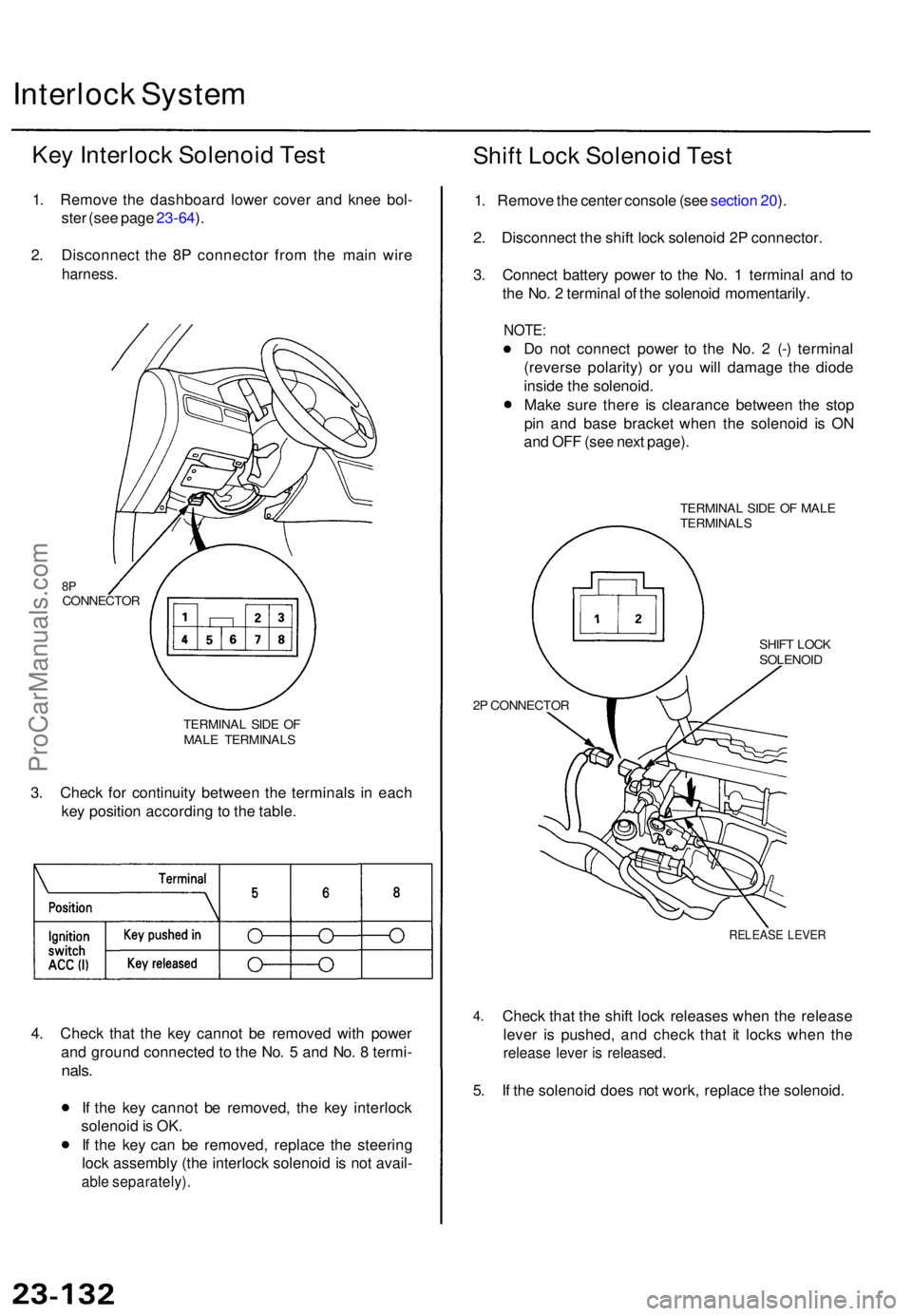
Key Interloc k Solenoi d Tes t
1. Remov e th e dashboar d lowe r cove r an d kne e bol -
ste r (se e pag e 23-64 ).
2 . Disconnec t th e 8 P connecto r fro m th e mai n wir e
harness .
TERMINA L SID E O F
MAL E TERMINAL S
3. Chec k fo r continuit y betwee n th e terminal s i n eac h
ke y positio n accordin g to th e table .
4 . Chec k tha t th e ke y canno t b e remove d wit h powe r
an d groun d connecte d t o th e No . 5 an d No . 8 termi -
nals.
If th e ke y canno t b e removed , th e ke y interloc k
solenoi d is OK .
I f th e ke y ca n b e removed , replac e th e steerin g
loc k assembl y (th e interloc k solenoi d is no t avail -
able separately) .
Shift Loc k Solenoi d Tes t
1. Remov e th e cente r consol e (se e sectio n 20 ).
2 . Disconnec t th e shif t loc k solenoi d 2 P connector .
3 . Connec t batter y powe r t o th e No . 1 termina l an d t o
th e No . 2 termina l o f th e solenoi d momentarily .
NOTE:
Do no t connec t powe r t o th e No . 2 (- ) termina l
(revers e polarity ) o r yo u wil l damag e th e diod e
insid e th e solenoid .
Mak e sur e ther e i s clearanc e betwee n th e sto p
pi n an d bas e bracke t whe n th e solenoi d i s O N
an d OF F (se e nex t page) .
TERMINA L SID E O F MAL E
TERMINAL S
2 P CONNECTO R SHIF
T LOC K
SOLENOI D
4.
RELEAS E LEVE R
Check tha t th e shif t loc k release s whe n th e releas e
leve r i s pushed , an d chec k tha t i t lock s whe n th e
releas e leve r i s released .
5. I f th e solenoi d doe s no t work , replac e th e solenoid .
8PCONNECTO R
ProCarManuals.com
Page 1612 of 1771
Shift Loc k Solenoi d Replacemen t
1. Remov e th e cente r consol e an d shif t leve r kno b (se e
sectio n 20 ).
2 . Disconnec t th e connector s fro m th e shif t loc k sole -
noi d an d parkin g pi n switch .
3 . Remov e th e tw o locknut s an d throug h bolts , the n
remov e th e A/ T gea r positio n panel .
SHIFT LEVE R KNO B
A/ T GEA R POSITIO N
PANEL
LOCKNUT S
9. 8 N- m (1. 0 kgf-m , 7. 2 Ibf-ft )
SHIFT LOC K
SOLENOI D
THROUGH BOLT S
4. Remov e th e tw o mountin g bolts , the n remov e th e
shif t loc k solenoid .
MOUNTIN G BOLT S
9. 8 N- m (1. 0 kgf-m , 7. 2 Ibf-ft )
SHIF T LOC K
SOLENOI D
BASE BRACKE TSTOP PI N
5. Instal l th e shif t loc k solenoi d i n th e revers e orde r o f
removal .
NOTE : Mak e sur e ther e i s clearanc e betwee n th e
sto p pi n an d bas e bracke t whe n th e solenoi d i s O N
and OFF .
SOLENOI DON
STO P PI N
SOLENOI D
OFF
CLEARANC E
BASE BRACKE T
CLEARANC E
ProCarManuals.com
Page 1613 of 1771
Interlock Syste m
Parkin g Pi n Switc h Test/Replacemen t
1. Remov e th e cente r consol e (se e sectio n 20 ).
2 . Disconnec t th e parkin g pi n switc h 2 P connector .
3 . Chec k fo r continuit y betwee n th e terminal s i n eac h
switc h leve r positio n accordin g t o th e table .
SHIFT LEVE R
PARKIN G PI N
SWITC H
2 P CONNECTO R
TERMINAL SID E O F
MAL E TERMINAL S
4. I f necessary, replace th e parkin g pi n switch . 5
. Remov e th e screw , the n remov e th e parkin g pi n
switc h fro m th e bas e bracket .
BASE BRACKE T
SCREW
PARKIN G PI N SWITC H
ProCarManuals.com
Page 1636 of 1771

Lighting Syste m
Front Parkin g Ligh t
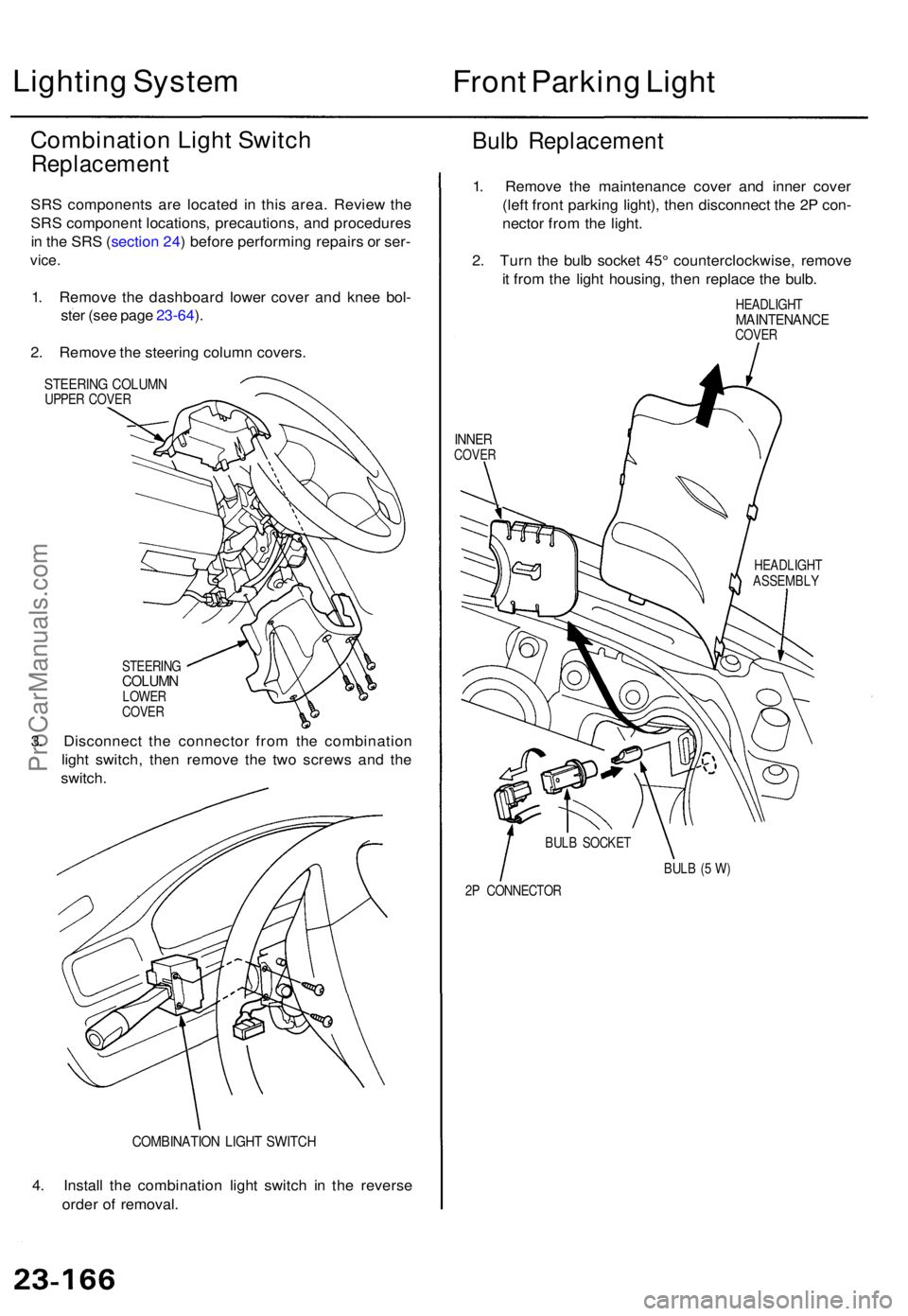
Combinatio n Ligh t Switc h
Replacemen t
SRS component s ar e locate d i n thi s area . Revie w th e
SR S componen t locations , precautions , an d procedure s
i n th e SR S (sectio n 24 ) befor e performin g repair s o r ser -
vice .
1. Remov e th e dashboar d lowe r cove r an d kne e bol -
ste r (se e pag e 23-64 ).
2 . Remov e th e steerin g colum n covers .
STEERIN G COLUM NUPPER COVE R
Bulb Replacemen t
STEERINGCOLUMNLOWER
COVE R
3. Disconnec t th e connecto r fro m th e combinatio n
ligh t switch , the n remov e th e tw o screw s an d th e
switch .
COMBINATIO N LIGH T SWITC H
4. Instal l th e combinatio n ligh t switc h i n th e revers e
orde r o f removal . 1
. Remov e th e maintenanc e cove r an d inne r cove r
(lef t fron t parkin g light) , the n disconnec t th e 2 P con -
necto r fro m th e light .
2 . Tur n th e bul b socke t 45 ° counterclockwise , remov e
i t fro m th e ligh t housing , the n replac e th e bulb .
HEADLIGH TMAINTENANC ECOVER
INNERCOVE R
HEADLIGH T
ASSEMBL Y
BUL B (5 W )
2 P CONNECTO R
BUL
B SOCKE T
ProCarManuals.com