Page 1261 of 1771

Pushrod Clearanc e Adjustmen t
NOTE: Maste r cylinde r pushrod-t o pisto n clearanc e mus t
b e checke d an d adjustment s made , i f necessary , befor e
installin g maste r cylinder .
1.
2 .
3.
4 .
5 .
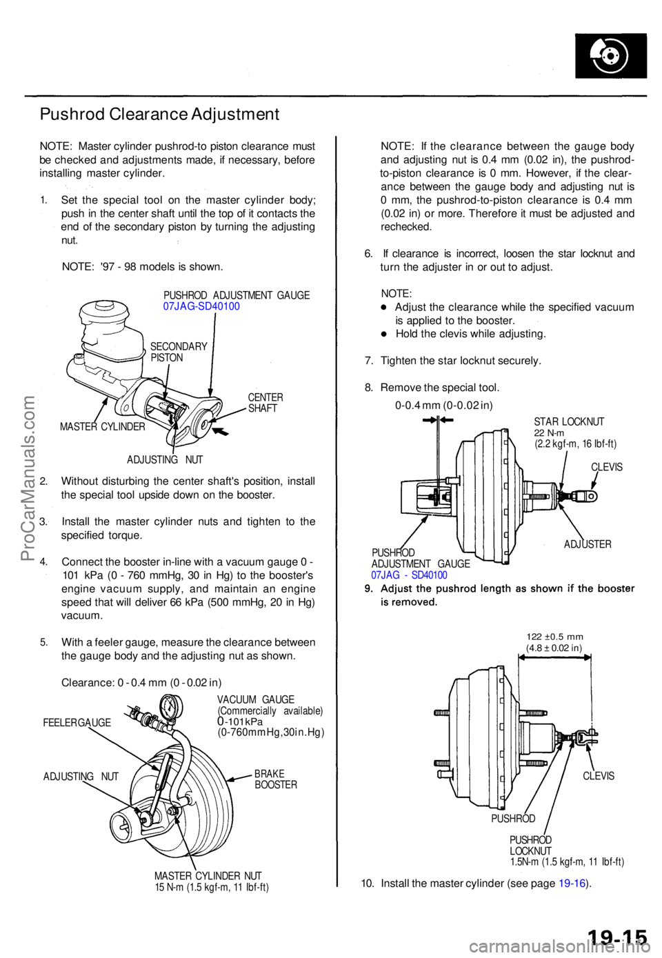
Se t th e specia l too l o n th e maste r cylinde r body ;
pus h in th e cente r shaf t unti l th e to p o f i t contact s th e
en d o f th e secondar y pisto n b y turnin g th e adjustin g
nut.
NOTE : '9 7 - 9 8 model s i s shown .
PUSHRO D ADJUSTMEN T GAUG E07JAG-SD4010 0
CENTERSHAFT
ADJUSTIN G NU T
Withou t disturbin g th e cente r shaft' s position , instal l
th e specia l too l upsid e dow n o n th e booster .
Instal l th e maste r cylinde r nut s an d tighte n t o th e
specifie d torque .
Connec t th e booste r in-lin e wit h a vacuu m gaug e 0 -
10 1 kP a ( 0 - 76 0 mmHg , 3 0 in Hg ) t o th e booster' s
engin e vacuu m supply , an d maintai n a n engin e
spee d tha t wil l delive r 6 6 kP a (50 0 mmHg , 2 0 in Hg )
vacuum .
With a feele r gauge , measur e th e clearanc e betwee n
th e gaug e bod y an d th e adjustin g nu t a s shown .
Clearance : 0 - 0. 4 m m (0 - 0.0 2 in )
FEELE R GAUG E
ADJUSTIN G NU T VACUU
M GAUG E
(Commerciall y available )0 -101 kPa(0-760mmHg,30in.Hg )
BRAKEBOOSTE R
MASTER CYLINDE R NU T
1 5 N- m (1. 5 kgf-m , 1 1 Ibf-ft )
NOTE : I f th e clearanc e betwee n th e gaug e bod y
an d adjustin g nu t i s 0. 4 m m (0.0 2 in) , th e pushrod -
to-pisto n clearanc e i s 0 mm . However , i f th e clear -
anc e betwee n th e gaug e bod y an d adjustin g nu t i s
0 mm , th e pushrod-to-pisto n clearanc e i s 0. 4 m m
(0.0 2 in ) o r more . Therefor e it mus t b e adjuste d an d
rechecked .
6. I f clearanc e i s incorrect , loose n th e sta r locknu t an d
tur n th e adjuste r i n o r ou t t o adjust .
NOTE:
Adjust th e clearanc e whil e th e specifie d vacuu m
i s applie d t o th e booster .
Hol d th e clevi s whil e adjusting .
7 . Tighte n th e sta r locknu t securely .
8 . Remov e th e specia l tool .
0-0. 4 m m (0-0.0 2 in )
STA R LOCKNU T22 N- m(2.2 kgf-m , 1 6 Ibf-ft )
PUSHRO D
LOCKNU T
1.5N- m (1. 5 kgf-m , 1 1 Ibf-ft )
10. Instal l th e maste r cylinde r (se e pag e 19-16 ).
MASTE R CYLINDE RSECONDAR
Y
PISTO N
CLEVIS
ADJUSTE R
PUSHRO D
ADJUSTMEN T GAUG E
07JA G - SD4010 0
122 ±0. 5 mm(4.8 ± 0.0 2 in)
CLEVI S
PUSHRO D
ProCarManuals.com
Page 1267 of 1771
Rear Brake Pads
Inspection and Replacement
• Never use an air hose or dry brush to clean brake
assemblies.
• Use an OSHA-approved vacuum cleaner to avoid
breathing brake dust.
1. Block the front wheels, loosen the rear wheel nuts
slightly, support the rear of vehicle on safety
stands, then remove the rear wheels.
2. Release the parking brake.
3. Remove the two caliper bolts and the caliper from
the bracket.
CAUTION:
• Thoroughly clean the outside of the caliper to pre-
vent dust and dirt from entering inside.
• Support the caliper with a piece of wire so that
it does not hang from the brake hose.
CALIPER BOLTS
CALIPER
4. Remove the pad shims and brake pads.
OUTER PAD
SHIM
Check for weakness.
INNER PAD
SHIM
Check for weakness.
REAR BRAKE PADS
Check for wear.ProCarManuals.com
Page 1268 of 1771

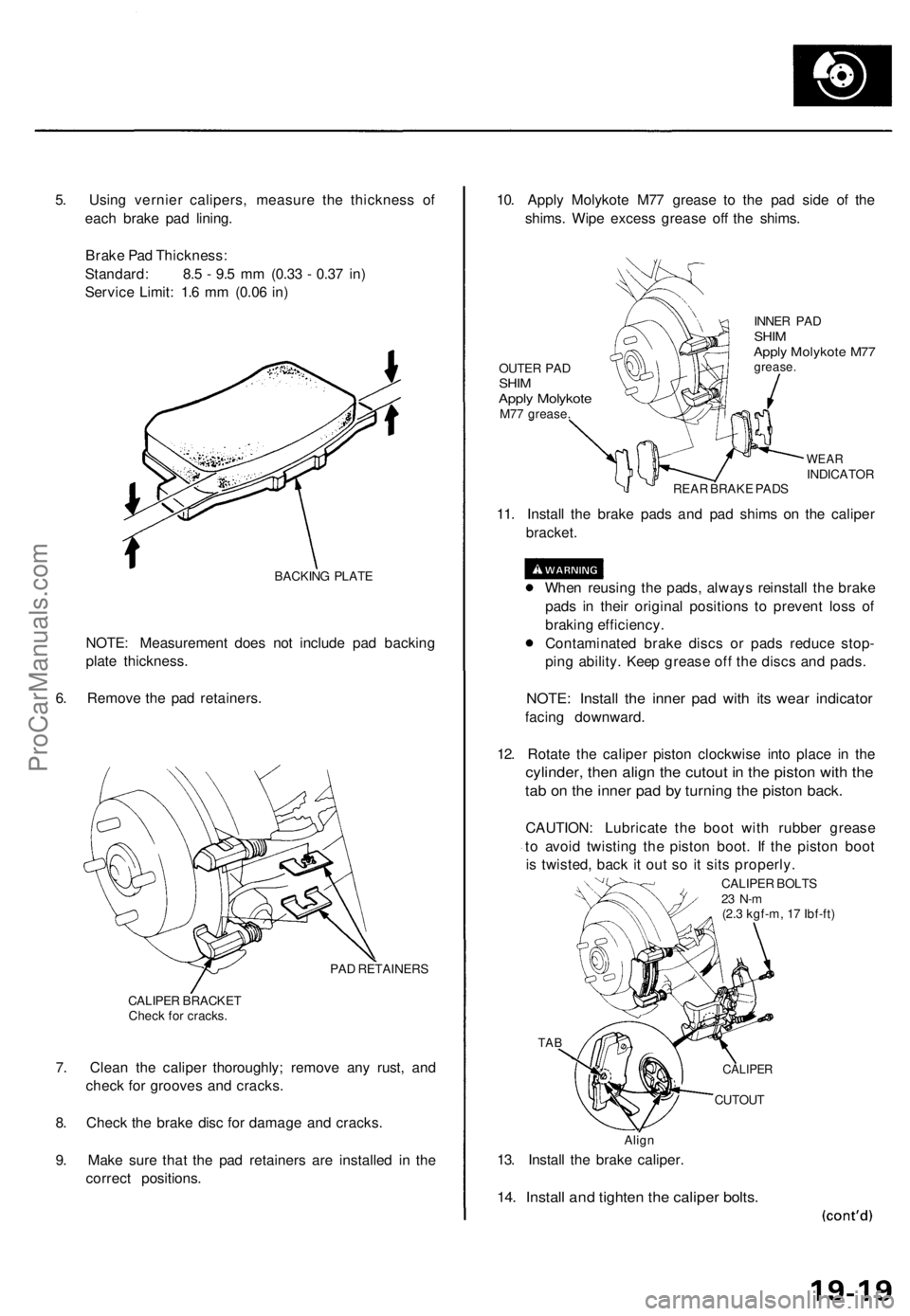
5. Using vernier calipers, measure the thickness of
each brake pad lining.
Brake Pad Thickness:
Standard: 8.5 - 9.5 mm (0.33 - 0.37 in)
Service Limit: 1.6 mm (0.06 in)
BACKING PLATE
NOTE: Measurement does not include pad backing
plate thickness.
6. Remove the pad retainers.
PAD RETAINERS
CALIPER BRACKET
Check for cracks.
7. Clean the caliper thoroughly; remove any rust, and
check for grooves and cracks.
8. Check the brake disc for damage and cracks.
9. Make sure that the pad retainers are installed in the
correct positions.
10. Apply Molykote M77 grease to the pad side of the
shims. Wipe excess grease off the shims.
OUTER PAD
SHIM
Apply Molykote
M77 grease.
INNER PAD
SHIM
Apply Molykote M77
grease.
WEAR
INDICATOR
REAR BRAKE PADS
11. Install the brake pads and pad shims on the caliper
bracket.
When reusing the pads, always reinstall the brake
pads in their original positions to prevent loss of
braking efficiency.
Contaminated brake discs or pads reduce stop-
ping ability. Keep grease off the discs and pads.
NOTE: Install the inner pad with its wear indicator
facing downward.
12. Rotate the caliper piston clockwise into place in the
cylinder, then align the cutout in the piston with the
tab on the inner pad by turning the piston back.
CAUTION: Lubricate the boot with rubber grease
to avoid twisting the piston boot. If the piston boot
is twisted, back it out so it sits properly.
CALIPER BOLTS
23 N-m
(2.3 kgf-m, 17 Ibf-ft)
TAB
CUTOUT
Align
13. Install the brake caliper.
14. Install and tighten the caliper bolts.
CALIPERProCarManuals.com
Page 1272 of 1771
Rear Brake Caliper
Disassembly
• Never use an air hose or dry brush to clean brake
assemblies.
• Use an OSHA-approved vacuum cleaner to avoid
breathing brake dust.
• Contaminated brake discs or pads reduce stopping
ability.
CAUTION:
• Do not spill brake fluid on the vehicle; it may damage
the paint; if brake fluid does contact the paint, wash
it off immediately with water.
• To prevent spills, cover the hose joints with rags or
shop towels.
• Clean all parts in brake fluid and air dry; blow out all
passages with compressed air.
1. Remove the caliper shield.
CALIPER SHIELD
2. Remove the lock pin and clevis pin. Remove the
cable clip, and disconnect the cable from the arm.
CLEVIS PIN
CABLE CLIP
Replace.
LOCK PIN
Replace.
PARKING BRAKE
CABLE
ARM
(cont'd)ProCarManuals.com
Page 1273 of 1771
Rear Brake Caliper
Disassembly (cont'd)
3. Remove the banjo bolt and two sealing washers.
CALIPER BRACKET
Check for cracks.
CALIPER BOLTS
SEALING
WASHERS
Replace.
BANJO
BOLT
4. Remove the two caliper bolts and caliper body from
the bracket.
5. Remove the pins and pin boots from the caliper
bracket.
PIN B
PIN A
PIN BOOTS
Replace.
6. Remove the pad spring from the caliper body.
PAD SPRING
7. Remove the piston by rotating the piston counter-
clockwise with the tool, and remove the piston
boot.
CAUTION: Avoid damaging the piston.
PISTON BOOT
Replace.
LOCKNUT WRENCH
(Commercially
available)
PISTON
Check for scoring.ProCarManuals.com
Page 1274 of 1771

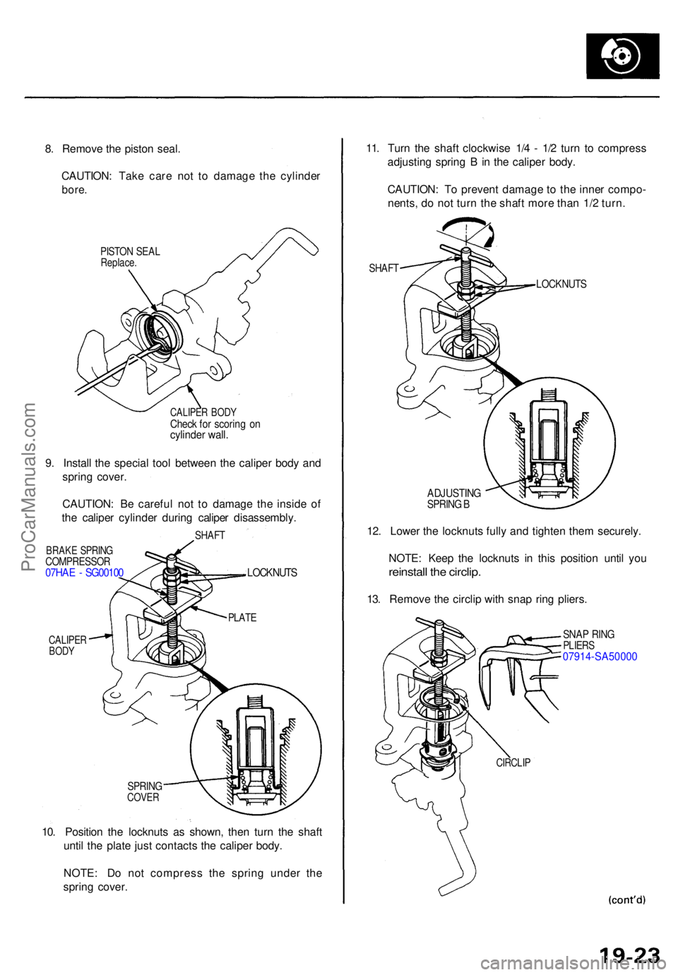
8. Remov e th e pisto n seal .
CAUTION : Tak e car e no t t o damag e th e cylinde r
bore.
PISTO N SEA LReplace .
CALIPER BOD YCheck fo r scorin g o ncylinde r wall .
9. Instal l th e specia l too l betwee n th e calipe r bod y an d
sprin g cover .
CAUTION : B e carefu l no t t o damag e th e insid e o f
th e calipe r cylinde r durin g calipe r disassembly .
SHAFT
BRAK E SPRIN GCOMPRESSO R07HAE - SG0010 0
CALIPERBODY
LOCKNUT S
SPRINGCOVER
10. Positio n th e locknut s a s shown , the n tur n th e shaf t
unti l th e plat e jus t contact s th e calipe r body .
NOTE : D o no t compres s th e sprin g unde r th e
sprin g cover . 11
. Tur n th e shaf t clockwis e 1/ 4 - 1/ 2 tur n t o compres s
adjustin g sprin g B in th e calipe r body .
CAUTION : T o preven t damag e t o th e inne r compo -
nents , d o no t tur n th e shaf t mor e tha n 1/ 2 turn .
SHAF T
LOCKNUT S
ADJUSTIN GSPRING B
12 . Lowe r th e locknut s full y an d tighte n the m securely .
NOTE : Kee p th e locknut s i n thi s positio n unti l yo u
reinstal l th e circlip .
13. Remov e th e circli p wit h sna p rin g pliers .
SNAP RIN GPLIER S07914-SA5000 0
CIRCLIP
PLATE
ProCarManuals.com
Page 1275 of 1771
Rear Brake Caliper
Disassembly (cont'd)
14. Hold the plate with your fingers, and turn the shaft
counterclockwise. Remove the special tool from the
caliper.
LOCKNUTS
PLATE
15. Remove the adjusting bolt.
ADJUSTING SPRING B
Check for weakness.
SPACER
SPRING COVER
Check for damage.
CUP
Replace.
ADJUSTING BOLT
Check for wear and
damage.
16. Remove the spring cover, adjusting spring B, spacer,
bearing A and cup from the adjusting bolt.
17. Remove the sleeve piston, and remove the pin from
the cam in the caliper body.
O-RING
Replace.
PIN
SLEEVE PISTON
Check for wear and
damage.
18. Remove the return spring.
RETURN
SPRING
PARKING LEVER/
CAM ASSEMBLY
Check for damage
CAM BOOT
Replace.
19. Remove the parking lever and cam as an assembly
from the caliper body.
CAUTION: Do not loosen the parking nut with the
cam installed in the caliper body. K the lever and shaft
must be separated, hold the lever in a vise and loosen
the parking nut.
20. Remove the cam boot.ProCarManuals.com
Page 1277 of 1771

Rear Brake Caliper
Reassembly (cont'd)
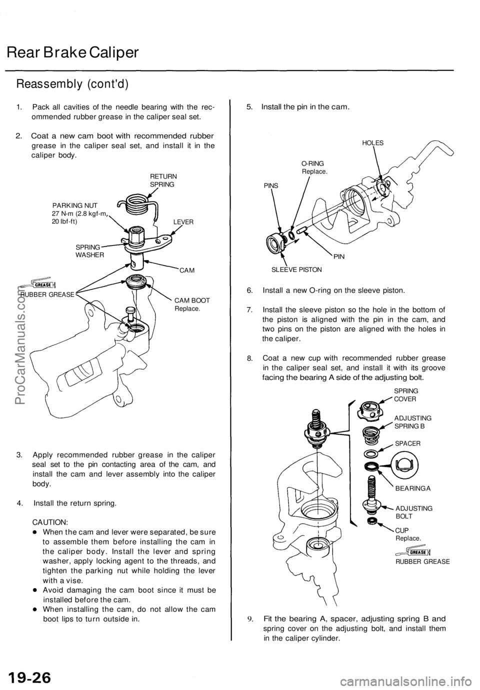
1. Pack all cavities of the needle bearing with the rec-
ommended rubber grease in the caliper seal set.
2. Coat a new cam boot with recommended rubber
grease in the caliper seal set, and install it in the
caliper body.
RETURN
SPRING
PARKING NUT
27 N-m (2.8 kgf-m
20 Ibf-ft)
SPRING
WASHER
RUBBER GREASE
LEVER
CAM
CAM BOOT
Replace.
3. Apply recommended rubber grease in the caliper
seal set to the pin contacting area of the cam, and
install the cam and lever assembly into the caliper
body.
4. Install the return spring.
CAUTION:
When the cam and lever were separated, be sure
to assemble them before installing the cam in
the caliper body. Install the lever and spring
washer, apply locking agent to the threads, and
tighten the parking nut while holding the lever
with a vise.
Avoid damaging the cam boot since it must be
installed before the cam.
When installing the cam, do not allow the cam
boot lips to turn outside in.
5. Install the pin in the cam.
HOLES
O-RING
Replace.
PINS
PIN
SLEEVE PISTON
6. Install a new O-ring on the sleeve piston.
7.
8.
Install the sleeve piston so the hole in the bottom of
the piston is aligned with the pin in the cam, and
two pins on the piston are aligned with the holes in
the caliper.
Coat a new cup with recommended rubber grease
in the caliper seal set, and install it with its groove
facing the bearing A side of the adjusting bolt.
SPRING
COVER
ADJUSTING
SPRING B
RUBBER GREASE
9.
Fit the bearing A, spacer, adjusting spring B and
spring cover on the adjusting bolt, and install them
in the caliper cylinder.
BEARING A
ADJUSTING
BOLT
CUP
Replace.
SPACERProCarManuals.com