Page 1232 of 1771
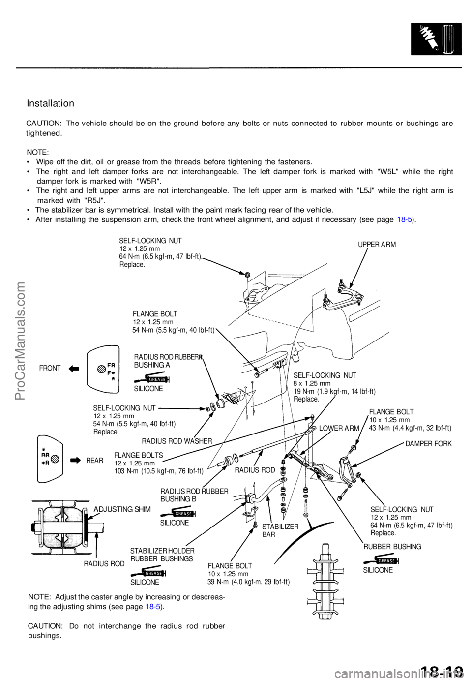
Installation
CAUTION: Th e vehicl e shoul d b e o n th e groun d befor e an y bolt s o r nut s connecte d t o rubbe r mount s o r bushing s ar e
tightened .
NOTE:
• Wip e of f th e dirt , oi l o r greas e fro m th e thread s befor e tightenin g th e fasteners .
• Th e righ t an d lef t dampe r fork s ar e no t interchangeable . Th e lef t dampe r for k i s marke d wit h "W5L " whil e th e righ t
dampe r for k i s marke d wit h "W5R" .
• Th e righ t an d lef t uppe r arm s ar e no t interchangeable . Th e lef t uppe r ar m is marke d wit h "L5J " whil e th e righ t ar m is
marke d wit h "R5J" .
• Th e stabilize r ba r i s symmetrical . Instal l wit h th e pain t mar k facin g rea r o f th e vehicle .
• Afte r installin g th e suspensio n arm , chec k th e fron t whee l alignment , an d adjus t i f necessar y (se e pag e 18-5 ).
SELF-LOCKIN G NU T12 x 1.2 5 mm64 N- m (6. 5 kgf-m , 4 7 Ibf-ft) .
Replace .
FLANG E BOL T
12 x 1.2 5 mm54 N- m (5. 5 kgf-m , 4 0 Ibf-ft ) UPPE
R AR M
FRON T RADIU
S RO D RUBBE R
BUSHIN G A
SILICON E
ADJUSTIN G SHI M
RADIU S RO D
SILICON E
NOTE: Adjus t th e caste r angl e b y increasin g o r descreas -
in g th e adjustin g shim s (se e pag e 18-5 ).
CAUTION : D o no t interchang e th e radiu s ro d rubbe r
bushings .
FLANGE BOL T10 x 1.2 5 mm43 N- m (4. 4 kgf-m , 3 2 Ibf-ft )
DAMPE R FOR K
SELF-LOCKIN G NU T
12 x 1.2 5 mm64 N- m (6. 5 kgf-m , 4 7 Ibf-ft )Replace .
RUBBER BUSHIN G
STABILIZE R HOLDE R
RUBBE R BUSHING S
SILICON
E
RADIU
S RO D RUBBE R
BUSHING B
FLANG E BOLT S12 x 1.2 5 mm103 N- m (10. 5 kgf-m , 7 6 Ibf-ft )
RADIU
S RO D WASHE R
SELF-LOCKIN
G NU T
12 x 1.2 5 mm54 N- m (5. 5 kgf-m , 4 0 Ibf-ft )Replace .
REAR
FLANG E BOL T10 x 1.2 5 mm39 N- m (4. 0 kgf-m . 2 9 Ibf-ft )
SILICON E
LOWER AR M
SELF-LOCKIN
G NU T
8 x 1.2 5 mm19 N- m (1. 9 kgf-m , 1 4 Ibf-ft )Replace .
RADIUS RO D
STABILIZE RBAR
ProCarManuals.com
Page 1233 of 1771
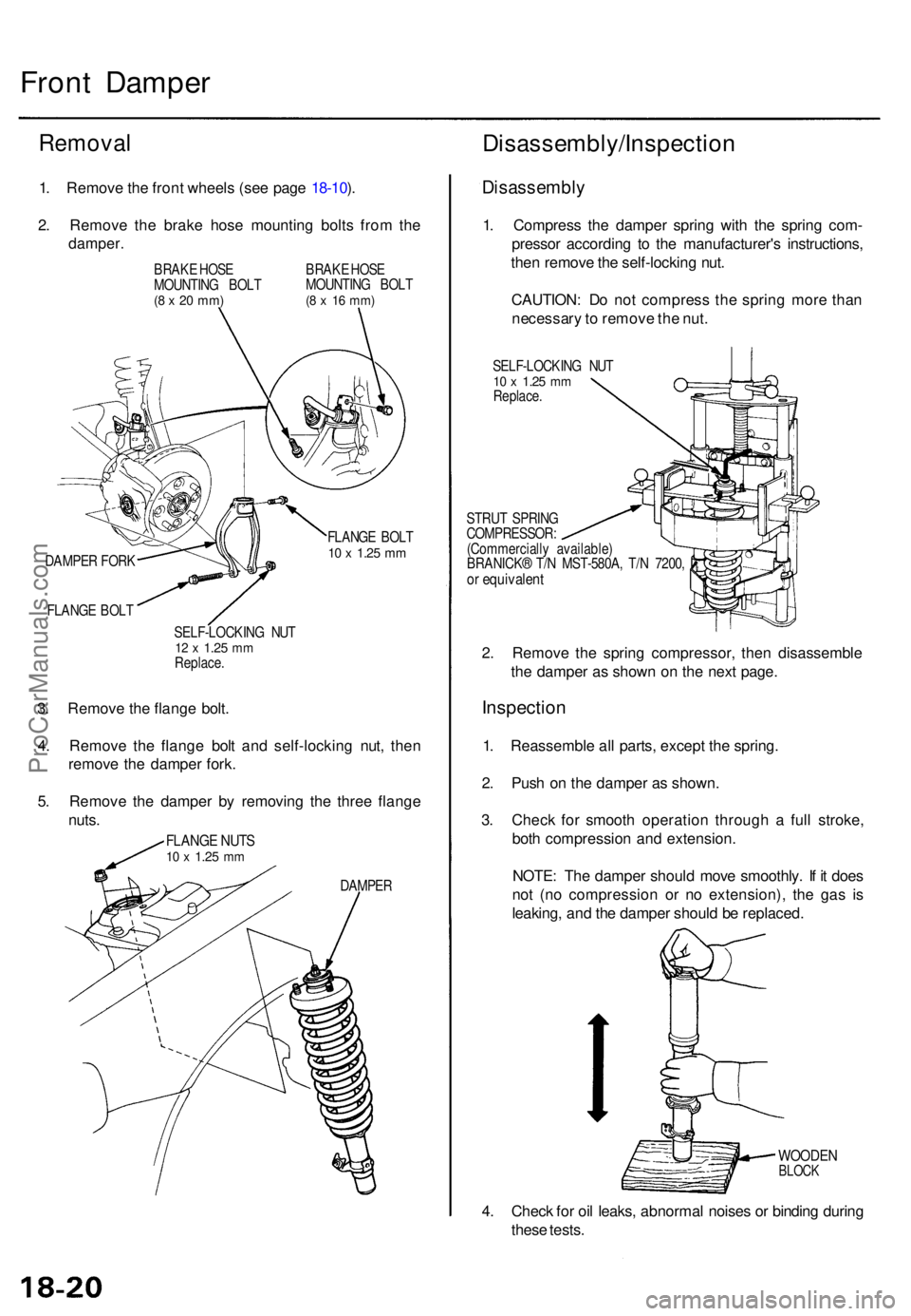
Front Dampe r
Remova l
1. Remov e th e fron t wheel s (se e pag e 18-10 ).
2 . Remov e th e brak e hos e mountin g bolt s fro m th e
damper .
BRAKE HOS E
MOUNTIN G BOL T
(8 x 2 0 mm )
BRAK E HOS E
MOUNTIN G BOL T
(8 x 1 6 mm )
DAMPE R FOR K
FLANG E BOL T FLANG
E BOL T10 x 1.2 5 mm
SELF-LOCKIN G NU T12 x 1.2 5 mmReplace .
3. Remov e th e flang e bolt .
4 . Remov e th e flang e bol t an d self-lockin g nut , the n
remov e th e dampe r fork .
5 . Remov e th e dampe r b y removin g th e thre e flang e
nuts .
FLANG E NUT S10 x 1.2 5 mm
DAMPE R
Disassembly/Inspectio n
Disassembly
1. Compres s th e dampe r sprin g wit h th e sprin g com -
presso r accordin g t o th e manufacturer' s instructions ,
the n remov e th e self-lockin g nut .
CAUTION : D o no t compres s th e sprin g mor e tha n
necessar y to remov e th e nut .
SELF-LOCKIN G NU T10 x 1.2 5 mmReplace .
STRU T SPRIN G
COMPRESSOR :
(Commerciall y available )
BRANICK ® T/ N MST-580A , T/ N 7200 ,
or equivalen t
2. Remov e th e sprin g compressor , the n disassembl e
th e dampe r a s show n o n th e nex t page .
Inspectio n
1. Reassemble all parts , excep t th e spring .
2 . Pus h o n th e dampe r a s shown .
3 . Chec k fo r smoot h operatio n throug h a ful l stroke ,
bot h compressio n an d extension .
NOTE : Th e dampe r shoul d mov e smoothly . I f i t doe s
no t (n o compressio n o r n o extension) , th e ga s i s
leaking , an d th e dampe r shoul d b e replaced .
WOODENBLOCK
4. Chec k fo r oi l leaks , abnorma l noise s o r bindin g durin g
thes e tests .
ProCarManuals.com
Page 1234 of 1771
Inspection
SELF-LOCKIN G NU T10 x 1.2 5 mm29 N- m (3. 0 kgf-m , 2 2 Ibf-ft )Replace .
DAMPER MOUNTIN GRUBBER
DAMPE R MOUNTIN GCOLLAR
DAMPE R MOUNTIN GBASE
DAMPE R MOUNTIN GRUBBER
DAMPE R MOUNTIN G WASHE R
'Chec k fo r weakness .
DAMPE R SPRIN G
Chec k fo r weakene d compressio n an d damage .
SPRIN G MOUNTIN G RUBBE R
Chec k fo r deterioratio n an d damage . BUM
P STO P PLAT E
BUM P STO P
Chec k fo r weaknes s an d
damage .
DUS T COVE R
Chec k fo r bendin g an d damag e
DUS
T COVE R PLAT E
DAMPER UNI T
ProCarManuals.com
Page 1235 of 1771
Front Dampe r
Reassembl y
1. Instal l th e dampe r uni t o n a sprin g compressor .
NOTE : Follo w th e manufacturer' s instructions .
2 . Assembl e th e dampe r i n revers e orde r o f disassembly ,
excep t th e dampe r mountin g washe r an d self-lockin g
nut.
NOTE : Alig n th e botto m o f dampe r sprin g an d sprin g
lowe r sea t a s shown .
STRUT SPRIN G COMPRESSOR :
(Commerciall y available )
BRANICK ® T/ N MST-580A , T/ N 7200 ,
o r equivalen t
SPRING LOWE R SEA T
3. Positio n th e dampe r mountin g bas e o n th e dampe r
unit a s shown .
Left:Right :
6°30' ± 3 °
ALIGNIN G TAB
4. Compres s th e dampe r sprin g wit h th e sprin g com -
pressor .
5 . Instal l th e dampe r mountin g washer , the n loosel y
install a ne w self-lockin g nut .
6. Hol d th e dampe r shaf t wit h a he x wrench , an d tight -
e n th e self-lockin g nut .
SELF-LOCKIN G NU TReplace .10 x 1.2 5 mm29 N- m (3. 0 kgf-m , 2 2 Ibf-ft )DAMPE RMOUNTIN G WASHE R
ProCarManuals.com
Page 1236 of 1771
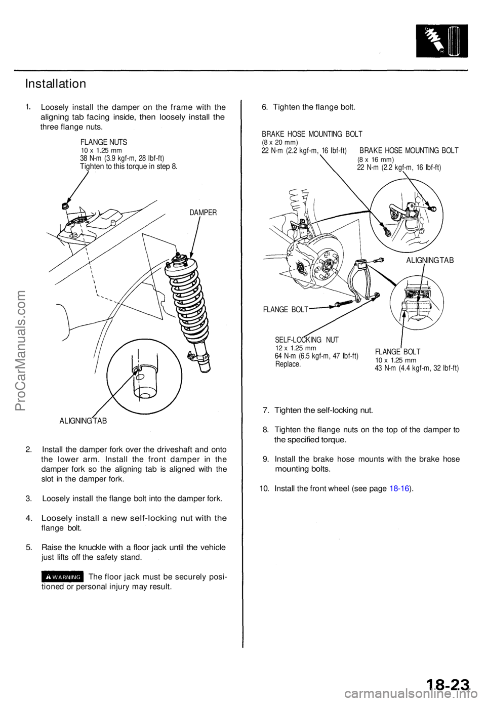
Installation
1. Loosel y instal l th e dampe r o n th e fram e wit h th e
alignin g ta b facin g inside , the n loosel y instal l th e
thre e flang e nuts .
FLANG E NUT S10 x 1.2 5 mm38 N- m (3. 9 kgf-m , 2 8 Ibf-ft )Tighte n to thi s torqu e in ste p 8 .
DAMPE R
ALIGNIN G TA B
2. Instal l th e dampe r for k ove r th e driveshaf t an d ont o
th e lowe r arm . Instal l th e fron t dampe r i n th e
dampe r for k s o th e alignin g ta b i s aligne d wit h th e
slo t i n th e dampe r fork .
3 . Loosel y instal l th e flang e bol t int o th e damper fork.
4. Loosel y instal l a ne w self-lockin g nu t wit h th e
flang e bolt .
5. Rais e th e knuckl e wit h a floo r jac k unti l th e vehicl e
just lift s of f th e safet y stand .
Th e floo r jac k mus t b e securel y posi -
tione d o r persona l injur y ma y result . 6
. Tighte n th e flang e bolt .
BRAK E HOS E MOUNTIN G BOL T(8 x 20 mm )22 N- m (2. 2 kgf-m , 1 6 Ibf-ft ) BRAK E HOS E MOUNTIN G BOL T(8 x 1 6 mm )22 N- m (2. 2 kgf-m , 1 6 Ibf-ft )
ALIGNIN G TA B
FLANG E BOL T
SELF-LOCKIN G NU T
12 x 1.2 5 mm64 N- m (6. 5 kgf-m , 4 7 Ibf-ft )
Replace . FLANG
E BOL T10 x 1.2 5 mm43 N- m (4. 4 kgf-m , 3 2 Ibf-ft )
7. Tighte n th e self-lockin g nut .
8. Tighte n th e flang e nut s o n th e to p o f th e damper to
th e specifie d torque .
9. Instal l th e brak e hos e mount s wit h th e brak e hos e
mountin g bolts .
10. Instal l th e fron t whee l (se e pag e 18-16 ).
ProCarManuals.com
Page 1237 of 1771
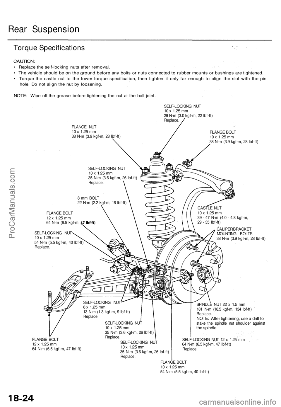
Rear Suspensio n
Torque Specification s
CAUTION:
• Replac e th e self-lockin g nut s afte r removal .
• Th e vehicl e shoul d b e o n th e groun d befor e an y bolt s o r nut s connecte d to rubbe r mount s o r bushing s ar e tightened .
• Torqu e th e castl e nu t t o th e lowe r torqu e specification , the n tighte n i t onl y fa r enoug h t o alig n th e slo t wit h th e pi n
hole . D o no t alig n th e nu t b y loosening .
NOTE : Wip e of f th e greas e befor e tightenin g th e nu t a t th e bal l joint .
SELF-LOCKIN G NU T10 x 1.2 5 mm29 N- m (3. 0 kgf-m , 2 2 Ibf-ft )Replace .
FLANGE NU T10 x 1.2 5 mm38 N- m (3. 9 kgf-m , 2 8 Ibf-ft ) FLANG
E BOL T10 x 1.2 5 mm38 N- m (3. 9 kgf-m , 2 8 Ibf-ft )
SELF-LOCKIN G NU T
10 x 1.2 5 mm35 N- m (3. 6 kgf-m , 2 6 Ibf-ft )Replace .
8 m m BOL T
2 2 N- m (2. 2 kgf-m , 1 6 Ibf-ft )
FLANG E BOL T
12 x 1.2 5 mm64 N- m (6. 5 kgf-m ,
SELF-LOCKIN G NU T
10 x 1.2 5 mm54 N- m (5. 5 kgf-m , 4 0 Ibf-ft )
Replace . CASTL
E NU T
10 x 1.2 5 mm39 - 4 7 N- m (4. 0 - 4. 8 kgf-m ,
2 9 - 3 5 Ibf-ft )
CALIPE R BRACKE T
MOUNTIN G BOLT S
3 8 N- m (3. 9 kgf-m , 2 8 Ibf-ft )
FLANG E BOL T
12 x 1.2 5 mm64 N- m (6. 5 kgf-m , 4 7 Ibf-ft )SELF-LOCKIN
G NU T
8 x 1.2 5 mm13 N- m (1. 3 kgf-m , 9 Ibf-ft )Replace .
SELF-LOCKIN G NU T10 x 1.2 5 mm35 N- m (3. 6 kgf-m , 2 6 Ibf-ft )Replace .
SELF-LOCKIN G NU T10 x 1.2 5 mm35 N- m (3. 6 kgf-m , 2 6 Ibf-ft )
Replace .
FLANGE BOL T
10 x 1.2 5 mm54 N- m (5. 5 kgf-m , 4 0 Ibf-ft )
SPINDL
E NU T 2 2 x 1. 5 m m
18 1 N- m (18. 5 kgf-m , 13 4 Ibf-ft )
Replace .NOTE: Afte r tightening , us e a drif t t ostak e th e spindl e nu t shoulde r agains tthe spindle .
SELF-LOCKIN G NU T 1 2 x 1.2 5 m m
6 4 N- m (6. 5 kgf-m , 4 7 Ibf-ft )
Replace .
ProCarManuals.com
Page 1239 of 1771
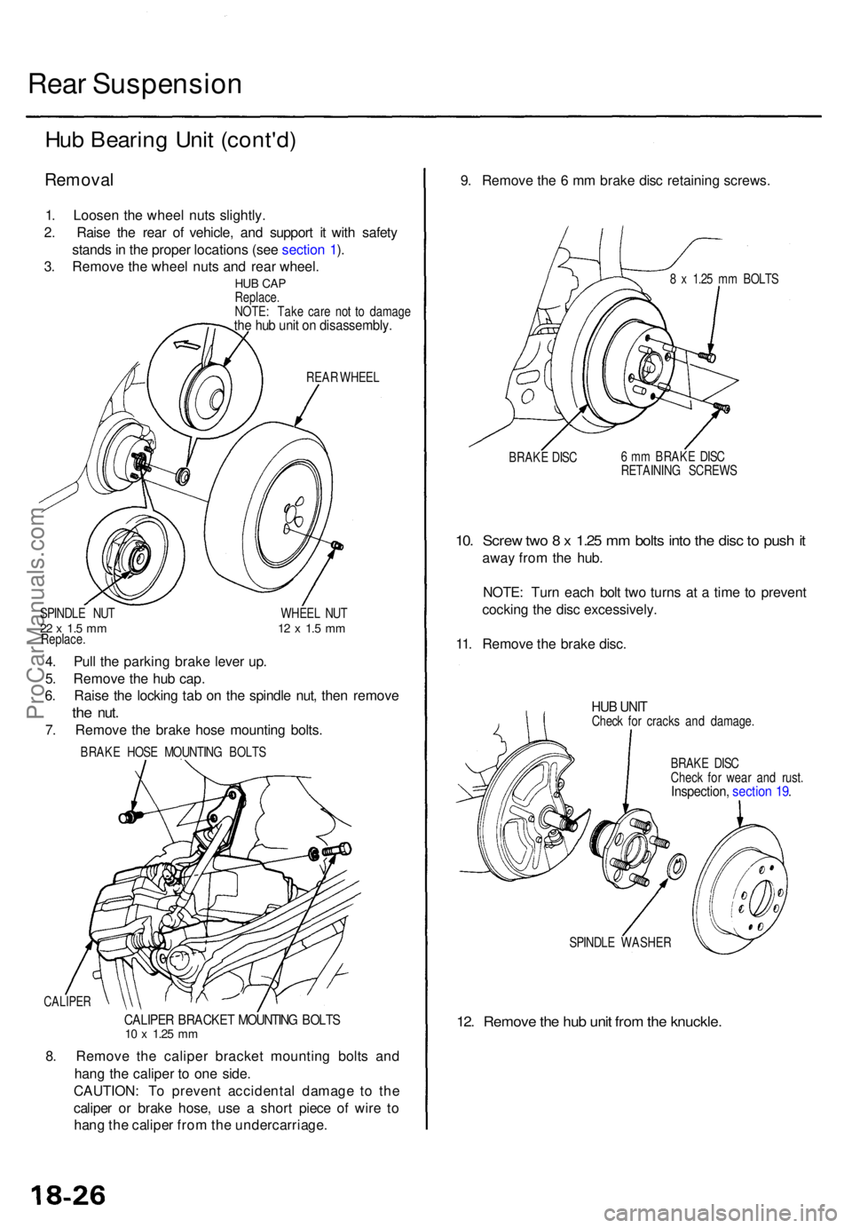
Rear Suspensio n
Hub Bearin g Uni t (cont'd )
Remova l
1. Loose n th e whee l nut s slightly .
2 . Rais e th e rea r o f vehicle , an d suppor t i t wit h safet y
stand s in th e prope r location s (se e sectio n 1 ).
3 . Remov e th e whee l nut s an d rea r wheel .
HUB CA PReplace .
NOTE : Tak e car e no t t o damag e
the hu b uni t o n disassembly .
REAR WHEE L
SPINDL E NU T WHEE L NU T
22 x 1. 5 m m 1 2 x 1. 5 m mReplace .
4. Pul l th e parkin g brak e leve r up .
5 . Remov e th e hu b cap .
6 . Rais e th e lockin g ta b o n th e spindl e nut , the n remov e
the nut .
7. Remov e th e brak e hos e mountin g bolts .
BRAK E HOS E MOUNTIN G BOLT S
CALIPE R
CALIPER BRACKE T MOUNTIN G BOLT S10 x 1.2 5 mm
8. Remov e th e calipe r bracke t mountin g bolt s an d
han g th e calipe r t o on e side .
CAUTION : T o preven t accidenta l damag e t o th e
calipe r o r brak e hose , us e a shor t piec e o f wir e t o
han g th e calipe r fro m th e undercarriage . 9
. Remov e th e 6 m m brak e dis c retainin g screws .
8 x 1.2 5 m m BOLT S
BRAK E DIS C 6
m m BRAK E DIS C
RETAININ G SCREW S
10. Scre w tw o 8 x 1.2 5 m m bolt s int o th e dis c to pus h it
awa y fro m th e hub .
NOTE : Tur n eac h bol t tw o turn s a t a tim e t o preven t
cockin g th e dis c excessively .
11 . Remov e th e brak e disc .
HUB UNI TChec k fo r crack s an d damage .
BRAK E DIS C
Chec k fo r wea r an d rust .
Inspection , sectio n 19 .
SPINDL E WASHE R
12. Remov e th e hu b uni t fro m th e knuckle .
ProCarManuals.com
Page 1241 of 1771
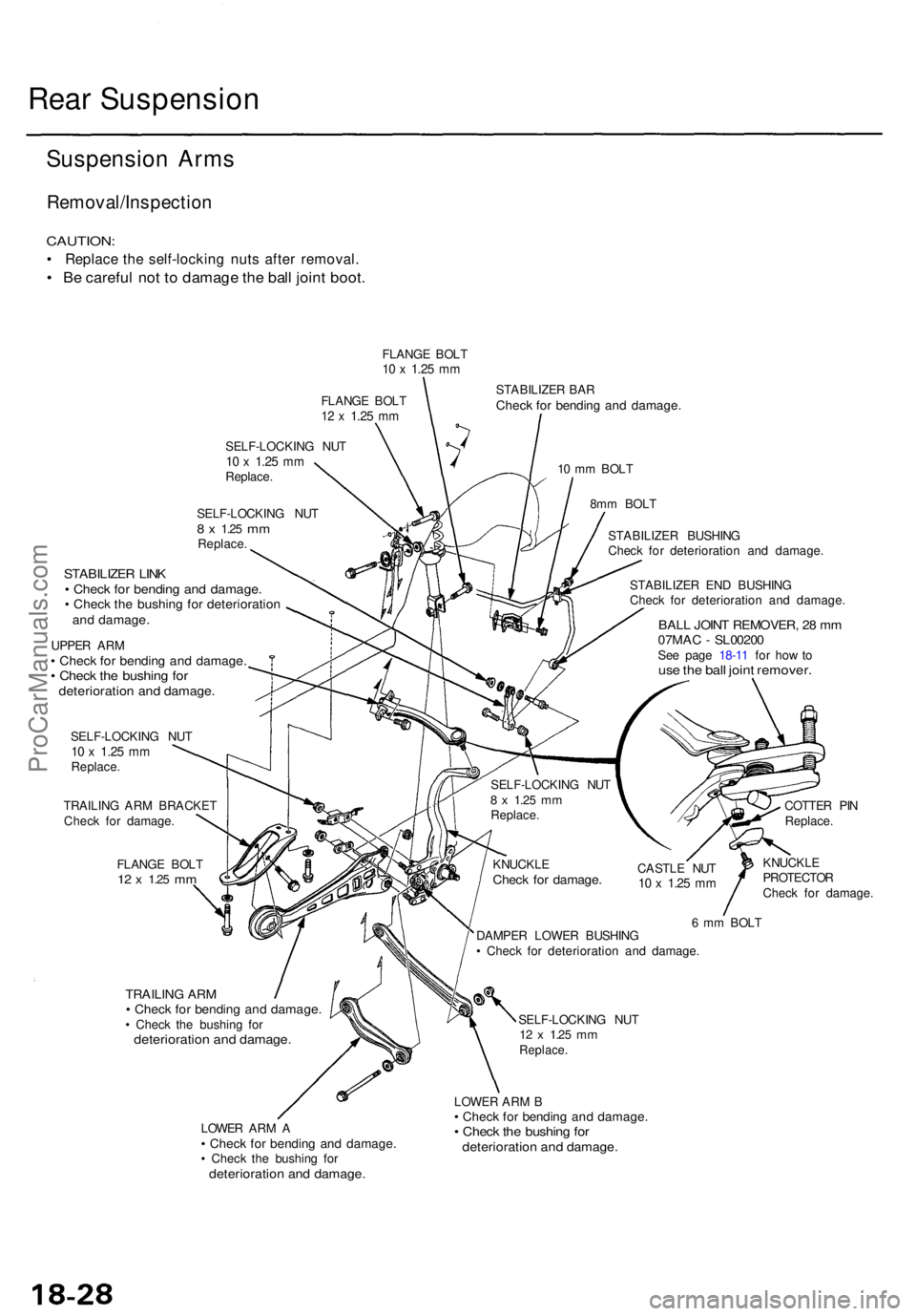
Rear Suspensio n
Suspension Arm s
Removal/Inspectio n
CAUTION:
• Replac e th e self-lockin g nut s afte r removal .
• B e carefu l no t t o damag e th e bal l join t boot .
FLANG E BOL T10 x 1.2 5 mm
FLANG E BOL T12 x 1.2 5 mm
SELF-LOCKIN G NU T10 x 1.2 5 mmReplace .
SELF-LOCKIN G NU T
8 x 1.2 5 mmReplace .
STABILIZE R BA RChec k fo r bendin g an d damage .
10 m m BOL T
8m m BOL T
STABILIZE R LIN K• Chec k fo r bendin g an d damage .• Chec k th e bushin g fo r deterioratio nand damage .
UPPER AR M• Chec k fo r bendin g an d damage .• Chec k th e bushin g fo rdeterioratio n an d damage .
SELF-LOCKIN G NU T10 x 1.2 5 mmReplace .
TRAILIN G AR M BRACKE T
Chec k fo r damage .
FLANG E BOL T
12 x 1.2 5 mm
STABILIZE R EN D BUSHIN G
Chec k fo r deterioratio n an d damage .
BALL JOIN T REMOVER , 2 8 m m07MA C - SL0020 0See pag e 18-1 1 fo r ho w tous e th e bal l join t remover .
CASTLE NU T10 x 1.2 5 mm
COTTE R PI N
Replace .
KNUCKL E
PROTECTO R
Chec k fo r damage .
TRAILING AR M• Chec k fo r bendin g an d damage .• Chec k th e bushin g fo rdeterioratio n an d damage .
LOWER AR M A• Chec k fo r bendin g an d damage .• Chec k th e bushin g fo rdeterioratio n an d damage .
6 m m BOL T
DAMPE R LOWE R BUSHIN G
• Chec k fo r deterioratio n an d damage .
SELF-LOCKIN G NU T
12 x 1.2 5 mmReplace .
LOWER AR M B• Chec k fo r bendin g an d damage .• Chec k th e bushin g fo rdeterioratio n an d damage .
KNUCKL ECheck fo r damage .
SELF-LOCKIN G NU T8 x 1.2 5 mmReplace . STABILIZE
R BUSHIN G
Chec k fo r deterioratio n an d damage .
ProCarManuals.com