1995 ACURA TL lock
[x] Cancel search: lockPage 1172 of 1771
Installation
Airbag installation
CAUTION:
• Before installing the steering wheel, align the front
wheels straight ahead.
• Be sure to install the harness wires so that they are
not pinched or interfering with other vehicle parts.
• Do not replace the original steering wheel with any
other design, since it will make it impossible to prop-
erly install the airbag. (Only use genuine Honda
replacement parts)
• After reassembly, confirm that the wheels are still
straight ahead and that steering wheel spoke angle
is correct. If minor spoke angle adjustment is neces-
sary, do so only by adjustment of the tie-rods, not by
removing and repositioning the steering wheel.
Confirm that the airbag assembly is
securely attached to the steering wheel; otherwise,
severe personal injury could result during airbag
deployment.
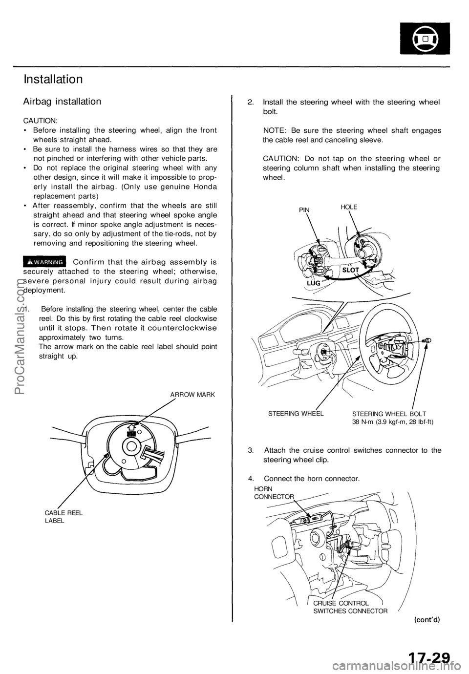
1. Before installing the steering wheel, center the cable
reel. Do this by first rotating the cable reel clockwise
until it stops. Then rotate it counterclockwise
approximately two turns.
The arrow mark on the cable reel label should point
straight up.
ARROW MARK
CABLE REEL
LABEL
2. Install the steering wheel with the steering wheel
bolt.
NOTE: Be sure the steering wheel shaft engages
the cable reel and canceling sleeve.
CAUTION: Do not tap on the steering wheel or
steering column shaft when installing the steering
wheel.
PIN
HOLE
STEERING WHEEL
STEERING WHEEL BOLT
38 N-m (3.9 kgf-m, 28 Ibf-ft)
3. Attach the cruise control switches connector to the
steering wheel clip.
4. Connect the horn connector.
HORN
CONNECTOR
CRUISE CONTROL
SWITCHES CONNECTORProCarManuals.com
Page 1173 of 1771
Steering Whee l
Installatio n (cont'd )
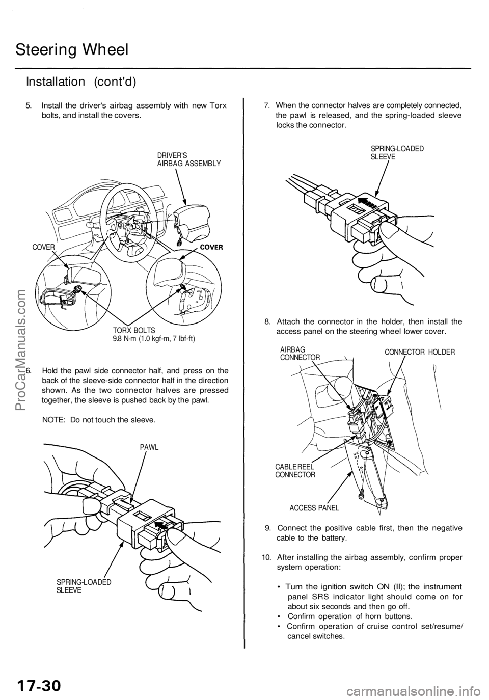
5. Instal l th e driver' s airba g assembl y wit h ne w Tor x
bolts , an d instal l th e covers .
DRIVER' S
AIRBA G ASSEMBL Y
COVER
6.
TOR X BOLT S9.8 N- m (1. 0 kgf-m , 7 Ibf-ft )
Hold th e paw l sid e connecto r half , an d pres s o n th e
bac k o f th e sleeve-sid e connecto r hal f i n th e directio n
shown . A s th e tw o connecto r halve s ar e presse d
together , th e sleev e is pushe d bac k b y th e pawl .
NOTE : D o no t touc h th e sleeve .
PAWL
SPRING-LOADE DSLEEVE
7.Whe n th e connecto r halve s ar e completel y connected ,
th e paw l i s released , an d th e spring-loade d sleev e
lock s th e connector .
SPRING-LOADE DSLEEVE
8. Attac h th e connecto r i n th e holder , the n instal l th e
acces s pane l o n th e steerin g whee l lowe r cover .
AIRBA GCONNECTO R CONNECTO
R HOLDE R
CABL E REE L
CONNECTO R
ACCES S PANE L
9. Connect the positiv e cabl e first , the n th e negativ e
cabl e t o th e battery .
10 . Afte r installin g th e airba g assembly , confir m prope r
syste m operation :
• Tur n th e ignitio n switc h O N (II) ; th e instrumen t
panel SR S indicato r ligh t shoul d com e o n fo r
abou t si x second s an d the n g o off .
• Confir m operatio n o f hor n buttons .
• Confir m operatio n o f cruis e contro l set/resume /
cance l switches .
ProCarManuals.com
Page 1190 of 1771
Power Steerin g Pum p
Installatio n
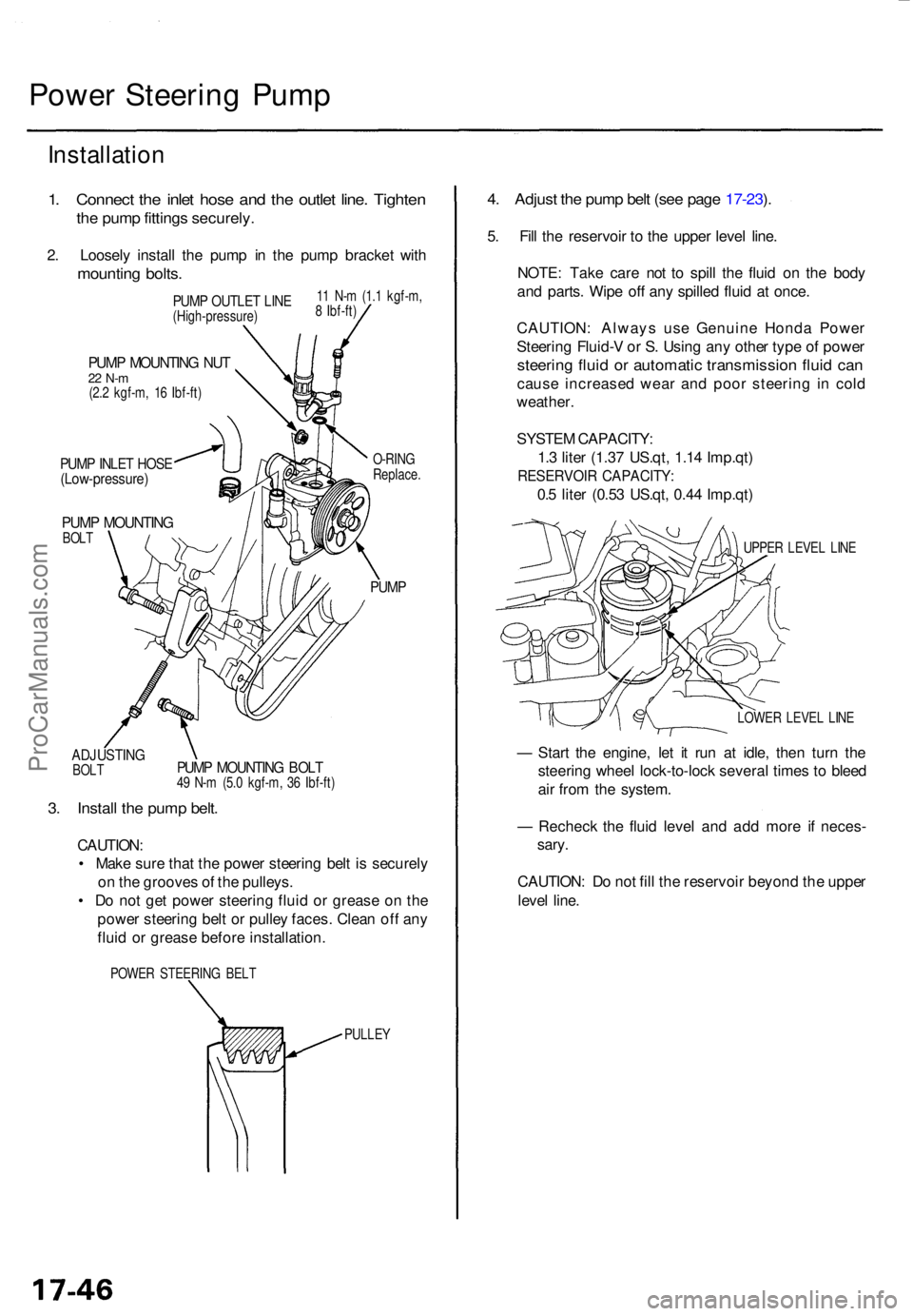
1. Connec t th e inle t hos e an d th e outle t line . Tighte n
the pum p fitting s securely .
2. Loosel y instal l th e pum p i n th e pum p bracke t wit h
mountin g bolts .
ADJUSTIN GBOLT
PUM P MOUNTIN G NU T22 N- m(2.2 kgf-m , 1 6 Ibf-ft )
PUMP INLE T HOS E(Low-pressure )
PUMP MOUNTIN GBOLT O-RIN
G
Replace .
PUMP
PUMP MOUNTIN G BOL T49 N- m (5. 0 kgf-m , 3 6 Ibf-ft )
3. Instal l th e pum p belt .
CAUTION :
• Mak e sur e tha t th e powe r steerin g bel t i s securel y
o n th e groove s o f th e pulleys .
• D o no t ge t powe r steerin g flui d o r greas e o n th e
powe r steerin g bel t o r pulle y faces . Clea n of f an y
flui d o r greas e befor e installation .
POWER STEERIN G BEL T
PULLEY
4. Adjus t th e pum p bel t (se e pag e 17-23 ).
5 . Fil l th e reservoi r t o th e uppe r leve l line .
NOTE : Tak e car e no t t o spil l th e flui d o n th e bod y
an d parts . Wip e of f an y spille d flui d a t once .
CAUTION : Alway s us e Genuin e Hond a Powe r
Steerin g Fluid- V o r S . Usin g an y othe r typ e o f powe r
steerin g flui d o r automati c transmissio n flui d ca n
caus e increase d wea r an d poo r steerin g i n col d
weather .
SYSTE M CAPACITY :
1. 3 lite r (1.3 7 US.qt , 1.1 4 Imp.qt )
RESERVOI R CAPACITY :
0.5 lite r (0.5 3 US.qt , 0.4 4 Imp.qt )
UPPER LEVE L LIN E
LOWE R LEVE L LIN E
— Star t th e engine , le t i t ru n a t idle , the n tur n th e
steerin g whee l lock-to-loc k severa l time s t o blee d
ai r fro m th e system .
— Rechec k th e flui d leve l an d ad d mor e i f neces -
sary .
CAUTION : D o no t fil l th e reservoi r beyon d th e uppe r
leve l line .
PUM P OUTLE T LIN E(High-pressure )1
1 N- m (1. 1 kgf-m ,
8 Ibf-ft )
ProCarManuals.com
Page 1193 of 1771
Disassembly
Steering Rac k Disassembl y
NOTE:
• Befor e disassemblin g th e steerin g gearbox , was h i t
of f wit h solven t an d a brush .
• D o no t di p seal s an d O-ring s i n solvent .
1 . Remov e th e steerin g gearbo x (se e pag e 17-47 ).
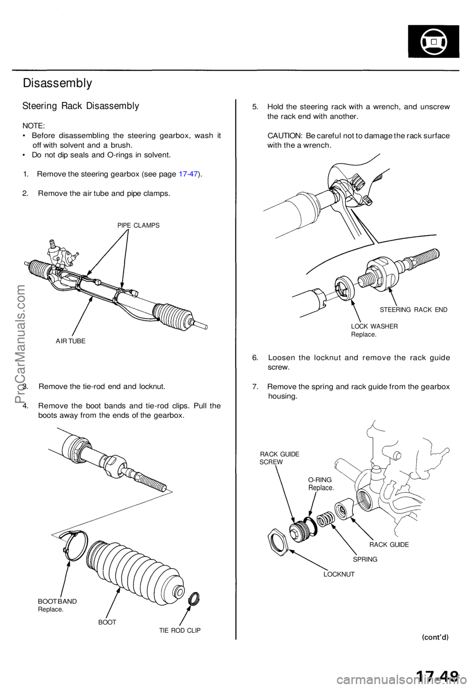
2 . Remov e th e ai r tub e an d pip e clamps .
PIPE CLAMP S
AIR TUB E
3. Remov e th e tie-ro d en d an d locknut .
4 . Remov e th e boo t band s an d tie-ro d clips . Pul l th e
boot s awa y fro m th e end s o f th e gearbox.
BOO T BAN DReplace .
BOOTTIE RO D CLI P
5. Hol d th e steerin g rac k wit h a wrench , an d unscre w
th e rac k en d wit h another .
CAUTION : B e carefu l no t t o damag e th e rac k surfac e
wit h th e a wrench .
STEERIN G RAC K EN D
LOC K WASHE RReplace.
6. Loose n th e locknu t an d remov e th e rac k guid e
screw .
7 . Remov e th e sprin g an d rac k guid e fro m th e gearbo x
housing .
RACK GUID ESCRE W
RACK GUID E
SPRIN G
LOCKNU T
O-RINGReplace .
ProCarManuals.com
Page 1200 of 1771
Steering Gearbo x
Reassembl y
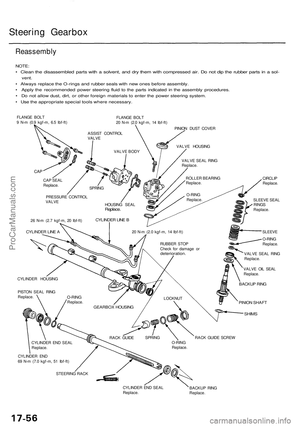
NOTE:
• Clea n th e disassemble d part s wit h a solvent , an d dr y the m wit h compresse d air . D o no t di p th e rubbe r part s in a sol -
vent .
• Alway s replac e th e O-ring s an d rubbe r seal s wit h ne w one s befor e assembly .
• Appl y th e recommende d powe r steerin g flui d t o th e part s indicate d i n th e assembl y procedures .
• D o no t allo w dust , dirt , o r othe r foreig n material s t o ente r th e powe r steerin g system .
• Us e th e appropriat e specia l tool s wher e necessary .
FLANGE BOL T
9 N- m (0. 9 kgf-m , 6. 5 Ibf-ft ) FLANG
E BOL T
2 0 N- m (2. 0 kgf-m , 1 4 Ibf-ft )
PINIO N DUS T COVE R
CYLINDE R HOUSIN G
PISTO N SEA L RIN G
Replace . CIRCLI
P
Replace .
SLEEV E SEA L
RING S
Replace .
SLEEV E
O-RIN G
Replace .
VALV E SEA L RIN G
Replace .
VALV E OI L SEA L
Replace .
BACKUP RIN G
PINIO N SHAF T
SHIMS
CYLINDE R EN D
6 9 N- m (7. 0 kgf-m , 5 1 Ibf-ft )
STEERIN G RAC K
CYLINDER EN D SEA L
Replace . BACKU
P RIN G
Replace .
ASSIST CONTRO L
VALV E
VALVE BOD Y VALV
E HOUSIN G
VALV E SEA L RIN G
Replace .
ROLLE R BEARIN G
Replace .
O-RIN G
Replace .
SPRIN
G
CAP
CA P SEA L
Replace .
HOUSING SEA L
Replace .
CYLINDE R LIN E B
20 N- m (2. 0 kgf-m , 1 4 Ibf-ft )
RUBBE R STO P
Chec k fo r damag e o r
deterioration .
LOCKNUT
GEARBO X HOUSIN G
RACK GUID E SPRIN
G
O-RING
Replace .RAC
K GUID E SCRE W
PRESSUR
E CONTRO L
VALV E
2 6 N- m (2. 7 kgf-m , 2 0 Ibf-ft )
CYLINDE R LIN E A
O-RIN GReplace .
CYLINDE R EN D SEA L
Replace .
ProCarManuals.com
Page 1208 of 1771
Steering Gearbo x
Reassembl y (cont'd )
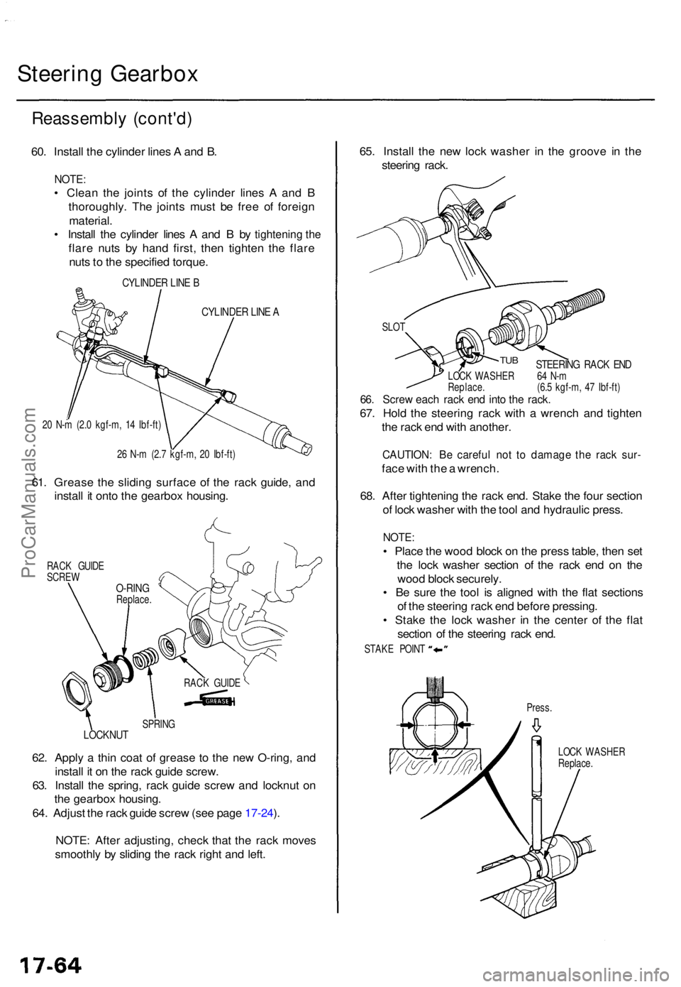
60. Instal l th e cylinde r line s A an d B .
NOTE :
• Clea n th e joint s o f th e cylinde r line s A an d B
thoroughly . Th e joint s mus t b e fre e o f foreig n
material .
• Instal l th e cylinde r line s A an d B by
tightening the
flar e nut s b y han d first , the n tighte n th e flar e
nut s t o th e specifie d torque .
CYLINDE R LIN E B
CYLINDE R LIN E A
20 N- m (2. 0 kgf-m , 1 4 Ibf-ft )
2 6 N- m (2. 7 kgf-m , 2 0 Ibf-ft )
61. Greas e th e slidin g surfac e o f th e rac k guide , an d
instal l i t ont o th e gearbo x housing .
RACK GUID E
SCRE W
SPRING
LOCKNU T
62. Appl y a thi n coa t o f greas e t o th e ne w O-ring , an d
instal l i t o n th e rac k guid e screw .
63 . Instal l th e spring , rac k guid e scre w an d locknu t o n
th e gearbo x housing .
64 . Adjus t th e rac k guid e scre w (se e pag e 17-24 ).
NOTE : Afte r adjusting , chec k tha t th e rac k move s
smoothl y b y slidin g th e rac k righ t an d left . 65
. Instal l th e ne w loc k washe r i n th e groov e i n th e
steerin g rack .
STEERIN G RAC K EN DLOC K WASHE R 6 4 N- m
Replace . (6. 5 kgf-m , 4 7 Ibf-ft )
66. Scre w eac h rac k en d int o th e rack .
67. Hol d th e steerin g rac k wit h a wrenc h an d tighte n
th e rac k en d wit h another .
CAUTION : B e carefu l no t t o damag e th e rac k sur -
face wit h th e a wrench .
68 . Afte r tightenin g th e rac k end . Stak e th e fou r sectio n
o f loc k washe r wit h th e too l an d hydrauli c press .
NOTE:
• Plac e th e woo d bloc k o n th e pres s table , the n se t
th e loc k washe r sectio n o f th e rac k en d o n th e
woo d bloc k securely .
• B e sur e th e too l i s aligne d wit h th e fla t section s
o f th e steerin g rac k en d befor e pressing .
• Stak e th e loc k washe r i n th e cente r o f th e fla t
sectio n o f th e steerin g rac k end .
Press .
LOC K WASHE R
Replace .
RAC
K GUID E
O-RINGReplace .
TUB
SLO T
STAK E POIN T
ProCarManuals.com
Page 1210 of 1771
Steering Gearbo x
Reassembl y (cont'd )
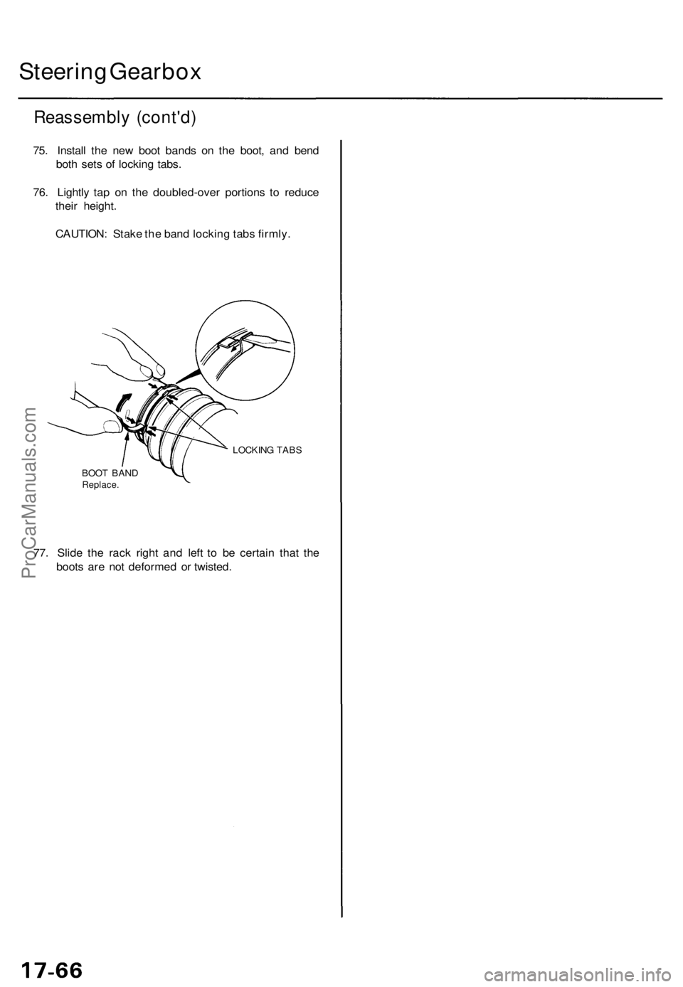
75. Instal l th e ne w boo t band s o n th e boot , an d ben d
bot h set s o f lockin g tabs .
76 . Lightl y ta p o n th e doubled-ove r portion s t o reduc e
thei r height .
CAUTION : Stak e th e ban d lockin g tab s firmly .
LOCKIN G TAB S
BOO T BAN D
Replace .
77. Slid e th e rac k righ t an d lef t t o b e certai n tha t th e
boot s ar e no t deforme d o r twisted .
ProCarManuals.com
Page 1212 of 1771
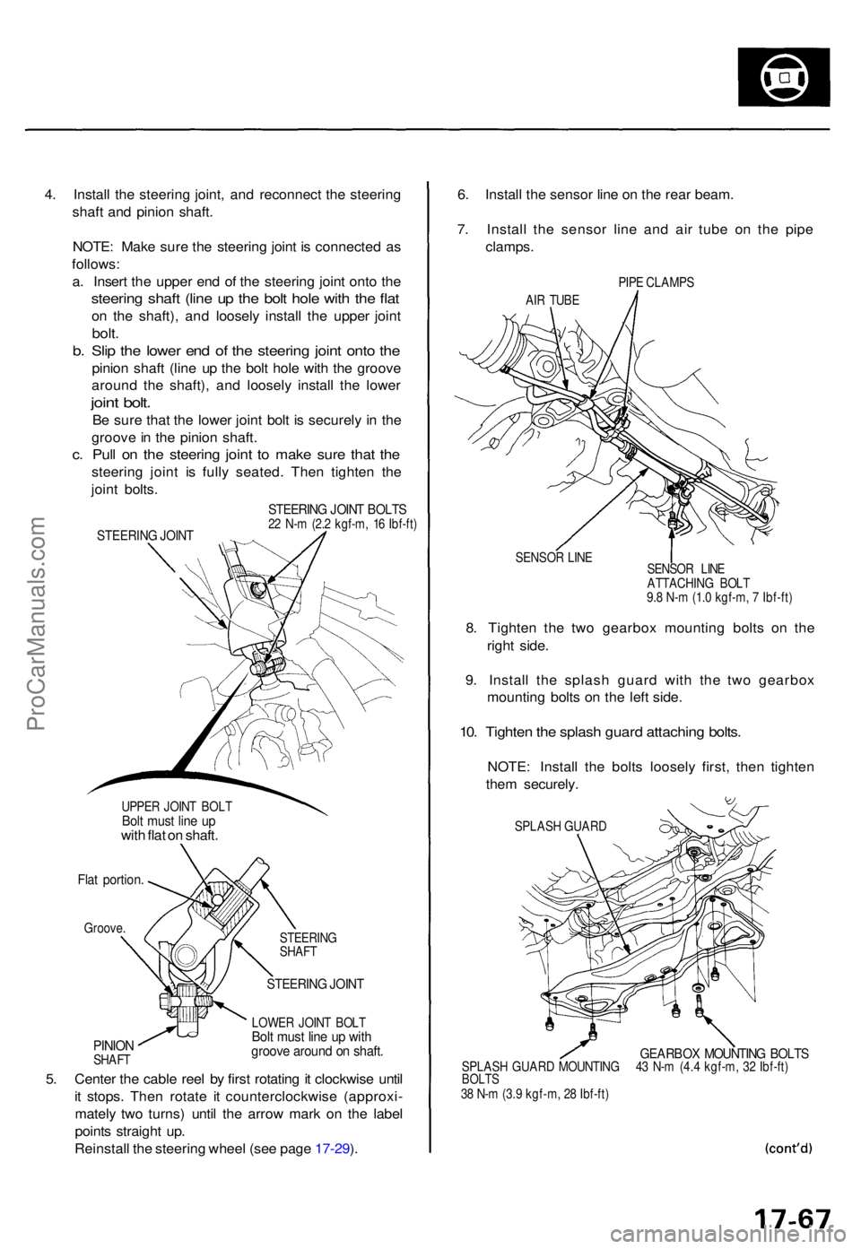
4. Instal l th e steerin g joint , an d reconnec t th e steerin g
shaf t an d pinio n shaft .
NOTE : Mak e sur e th e steerin g join t i s connecte d a s
follows :
a . Inser t th e uppe r en d o f th e steerin g join t ont o th e
steerin g shaf t (lin e u p th e bol t hol e wit h th e fla t
on th e shaft) , an d loosel y instal l th e uppe r join t
bolt.
b. Sli p th e lowe r en d o f th e steerin g join t ont o th e
pinio n shaf t (lin e u p th e bol t hol e wit h th e groov e
aroun d th e shaft) , an d loosel y instal l th e lowe r
joint bolt .
Be sur e tha t th e lowe r join t bol t i s securel y i n th e
groov e in th e pinio n shaft .
c. Pul l o n th e steerin g join t t o mak e sur e tha t th e
steerin g join t i s full y seated . The n tighte n th e
join t bolts .
UPPE R JOIN T BOL TBolt mus t lin e u pwit h fla t o n shaft .
Flat portion .
Groove.
PINIONSHAF T STEERIN
G
SHAF T
STEERIN G JOIN T
LOWE R JOIN T BOL TBolt mus t lin e u p wit hgroov e aroun d o n shaft .
5. Cente r th e cabl e ree l b y firs t rotatin g it clockwis e unti l
i t stops . The n rotat e i t counterclockwis e (approxi -
matel y tw o turns ) unti l th e arro w mar k o n th e labe l
point s straigh t up .
Reinstal l th e steerin g whee l (se e pag e 17-29 ). 6
. Instal l th e senso r lin e o n th e rea r beam .
7 . Instal l th e senso r lin e an d ai r tub e o n th e pip e
clamps .
PIPE CLAMP S
AI R TUB E
SENSO R LIN E
8. Tighte n th e tw o gearbo x mountin g bolt s o n th e
righ t side .
9 . Instal l th e splas h guar d wit h th e tw o gearbo x
mountin g bolt s o n th e lef t side .
10. Tighte n th e splas h guar d attachin g bolts .
NOTE : Instal l th e bolt s loosel y first , the n tighte n
the m securely .
SPLASH GUAR D
GEARBO X MOUNTIN G BOLT SSPLAS H GUAR D MOUNTIN G 4 3 N- m (4. 4 kgf-m , 3 2 Ibf-ft )BOLT S38 N- m (3. 9 kgf-m , 2 8 Ibf-ft )
STEERIN G JOIN T BOLT S22 N- m (2. 2 kgf-m , 1 6 Ibf-ft )STEERIN G JOIN T
SENSO R LIN E
ATTACHIN G BOL T
9. 8 N- m (1. 0 kgf-m , 7 Ibf-ft )
ProCarManuals.com