Page 1022 of 1771
1. Remov e th e on e bol t securin g th e A/ T gea r positio n
switc h harnes s clamp .
2. Remov e th e eigh t bolt s securin g th e rea r cover , the n
remov e th e rea r cover .
3. Remov e th e fou r AT F fee d pipe s fro m th e transmis -
sion housing .
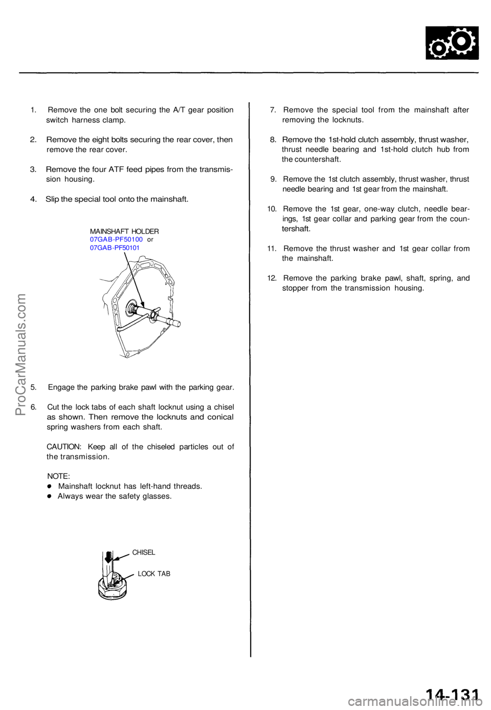
4. Sli p th e specia l too l ont o th e mainshaft .
MAINSHAF T HOLDE R07GAB-PF5010 0 o r07GA B-PF5010 1
5. Engag e th e parkin g brak e paw l wit h th e parkin g gear .
6 . Cu t th e loc k tab s o f eac h shaf t locknu t usin g a chise l
as shown . The n remov e th e locknut s an d conica l
spring washer s fro m eac h shaft .
CAUTION : Kee p al l o f th e chisele d particle s ou t o f
th e transmission .
NOTE :
Mainshaf t locknu t ha s left-han d threads .
Alway s wea r th e safet y glasses . 7
. Remov e th e specia l too l fro m th e mainshaf t afte r
removin g th e locknuts .
8. Remov e th e 1st-hol d clutc h assembly , thrus t washer ,
thrust needl e bearin g an d 1st-hol d clutc h hu b fro m
th e countershaft .
9 . Remov e th e 1s t clutc h assembly , thrus t washer , thrus t
needl e bearin g an d 1s t gea r fro m th e mainshaft .
10 . Remov e th e 1s t gear , one-wa y clutch , needl e bear -
ings , 1s t gea r colla r an d parkin g gea r fro m th e coun -
tershaft .
11. Remov e th e thrus t washe r an d 1s t gea r colla r fro m
th e mainshaft .
12 . Remov e th e parkin g brak e pawl , shaft , spring , an d
stoppe r fro m th e transmissio n housing .
LOCK TA B
CHISE L
ProCarManuals.com
Page 1025 of 1771
Torque Converter Housing/Valve Body
Removal
NOTE:
Clean all parts thoroughly in solvent or carburetor cleaner, and dry with compressed air.
Blow out all passages.
When removing the valve bodies, replace the following:
O-rings
Filters
2ND ACCUMULATOR
BODY
ATF FEED PIPE
THROTTLE
VALVE BODY
SEPARATOR
PLATE
2ND ACCUMULATOR
SPRING
2ND ACCUMULATOR
PISTON
ATF FEED PIPES
6 x 1.0 mm BOLTS
9 Bolts
REGULATOR VALVE BODY
STATOR SHAFT
STOPPER SHAFT
REGULATOR
SEPARATOR PLATE
ATF PUMP BODY
ATF FEED PIPES
8 x 1.25 mm BOLTS
3 Bolts
6 x 1.0 mm BOLTS
2 Bolts
ATF PUMP DRIVE GEAR
ATF PUMP DRIVEN GEAR
TORQUE CONVERTER
CHECK VALVE
TORQUE CONVERTER
CHECK VALVE SPRING
ATF PUMP BODY
SEPARATOR PLATE
ATF PUMP DRIVEN GEAR SHAFT
LOCK-UP CONTROL
SOLENOID VALVE
CONNECTOR
LINEAR SOLENOID
CONNECTOR
TORQUE CONVERTER
HOUSING
LINEAR SOLENOID
HARNESS CONNECTOR
LINEAR SOLENOID
HARNESS
HARNESS
CLAMP
THROTTLE VALVE
BODY/LINEAR
SOLENOID ASSEMBLY
FLANGE NUTSProCarManuals.com
Page 1026 of 1771
1. Remove the ATF feed pipe from the ATF pump
body and two ATF feed pipes from the torque con-
verter housing.
2. Remove the two flange nuts securing the linear
solenoid harness, then disconnect the harness from
the linear solenoid and harness clamp.
3. Remove the regulator valve body (nine bolts).
4. Remove the stopper shaft and stator shaft.
5. Remove the regulator separator plate with two dowel
pins.
6. Remove the six bolts securing the 2nd accumulator
body, then remove the 2nd accumulator body and
throttle valve body/linear solenoid as an assembly.
7. Remove the ATF pump body (five bolts).
8. Remove the ATF pump gears and ATF pump driven
gear shaft.
9. Remove the torque converter check valve and spring.
10. Remove the ATF pump body separator plate with
three dowel pins.
11. Remove the one bolt securing the linear solenoid
harness connector, then remove the linear solenoid
harness from the torque converter housing.
12. Disconnect the lock-up control solenoid valve con-
nector, then remove the transmission sub-harness.ProCarManuals.com
Page 1033 of 1771
ATF Pum p Bod y
Disassembly/lnspection/Reassembl y
NOTE:
Clean al l part s thoroughl y i n solven t o r carbureto r cleaner , an d dr y wit h compresse d air . Blo w ou t al l passages .
Replace th e valv e bod y a s a n assembl y if an y part s ar e wor n o r damaged .
Check al l valve s fo r fre e movement . I f an y fai l t o slid e freely , se e Valv e Bod y Repai r o n pag e 14-136 .
Coa t al l part s wit h AT F durin g assembly .
Instal l th e filter s i n th e directio n shown .
VALVE SLEEV E
LOCK-U P CONTRO L VALV E
LOCK-U P TIMIN G VALV E
SPRIN G SEA T VALV
E CA P
ROLLE R
RELIEF VALV E
MODULATO R VALV E
ATF PUM P BOD Y
Inspec t fo r wear , scratche sand scoring .
TORQUE CONVERTE R CHEC K VALV E
SPRING SPECIFICATION SUnit: m m (in )
FILTE RReplace .
FILTE R
Replace .
ProCarManuals.com
Page 1035 of 1771
Regulator Valv e Bod y
Disassembly/lnspection/Reassembl y
NOTE:
Clean al l part s thoroughl y i n solven t o r carbureto r cleaner , an d dr y wit h compresse d air . Blo w ou t al l passages .
Replac e th e valv e bod y a s a n assembl y i f an y part s ar e wor n o r damaged .
Chec k al l valve s fo r fre e movement . I f an y fai l t o slid e freely , se e Valv e Bod y Repai r o n pag e 14-136 .
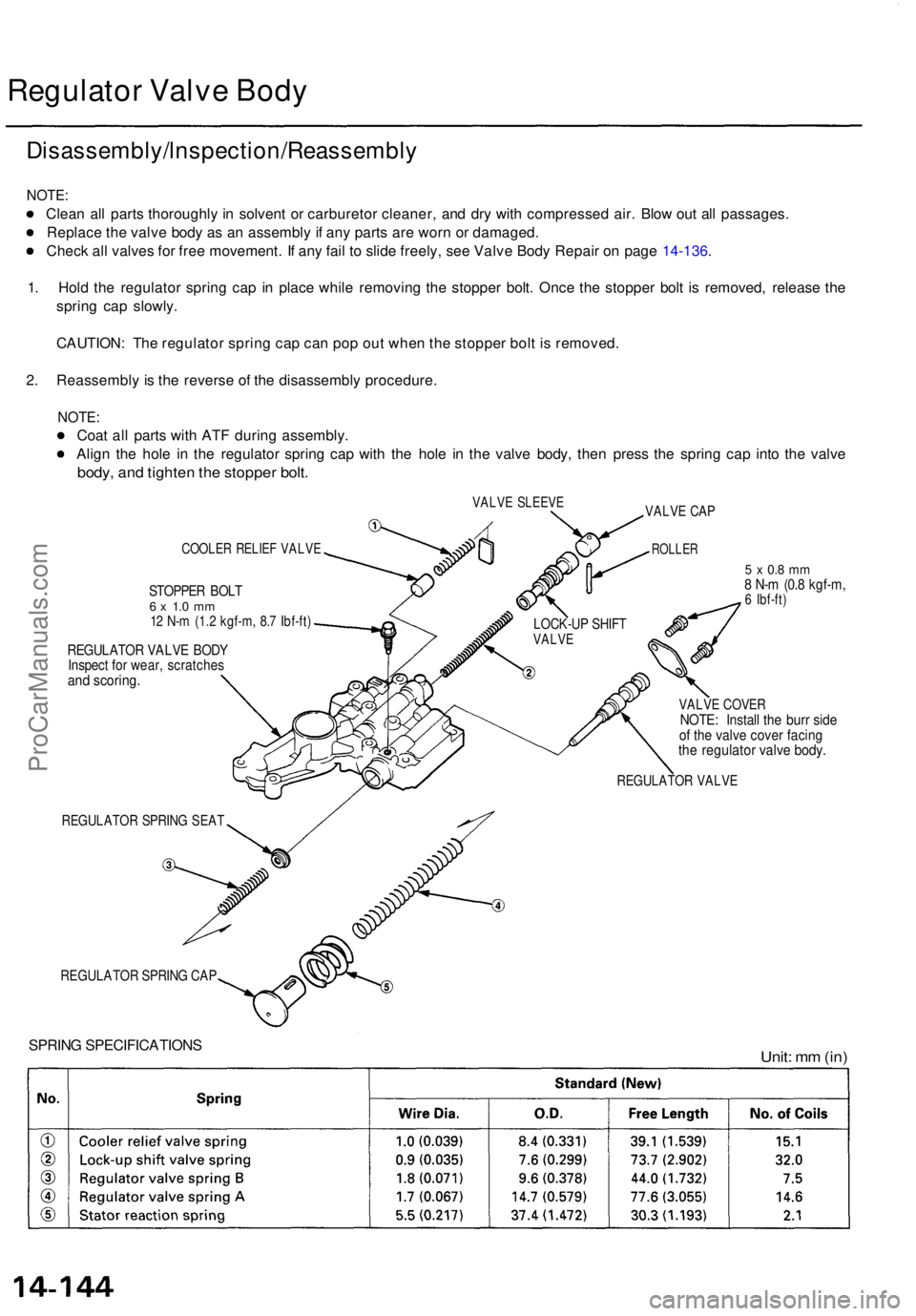
1 . Hol d th e regulato r sprin g ca p i n plac e whil e removin g th e stoppe r bolt . Onc e th e stoppe r bol t i s removed , releas e th e
sprin g ca p slowly .
CAUTION : Th e regulato r sprin g ca p ca n po p ou t whe n th e stoppe r bol t i s removed .
2 . Reassembl y i s th e revers e o f th e disassembl y procedure .
NOTE:
Coat al l part s wit h AT F durin g assembly .
Alig n th e hol e i n th e regulato r sprin g ca p wit h th e hol e i n th e valv e body , the n press the sprin g ca p int o th e valv e
body, an d tighte n th e stoppe r bolt .
VALV E SLEEV E
COOLER RELIE F VALV E
STOPPE R BOL T6 x 1. 0 m m12 N- m (1. 2 kgf-m , 8. 7 Ibf-ft )
REGULATO R VALV E BOD YInspec t fo r wear , scratche sand scoring .
REGULATO R SPRIN G SEA T
REGULATO R SPRIN G CA P
SPRIN G SPECIFICATION S
5 x 0. 8 m m8 N- m (0. 8 kgf-m ,6 Ibf-ft )
VALV E COVE RNOTE: Instal l th e bur r sid eof th e valv e cove r facin gthe regulato r valv e body .
REGULATO R VALV E
Unit: m m (in )
VALV E CA P
ROLLE R
LOCK-U P SHIF TVALV E
ProCarManuals.com
Page 1039 of 1771
Mainshaft
Disassembly/lnspection/Reassembl y
NOTE:
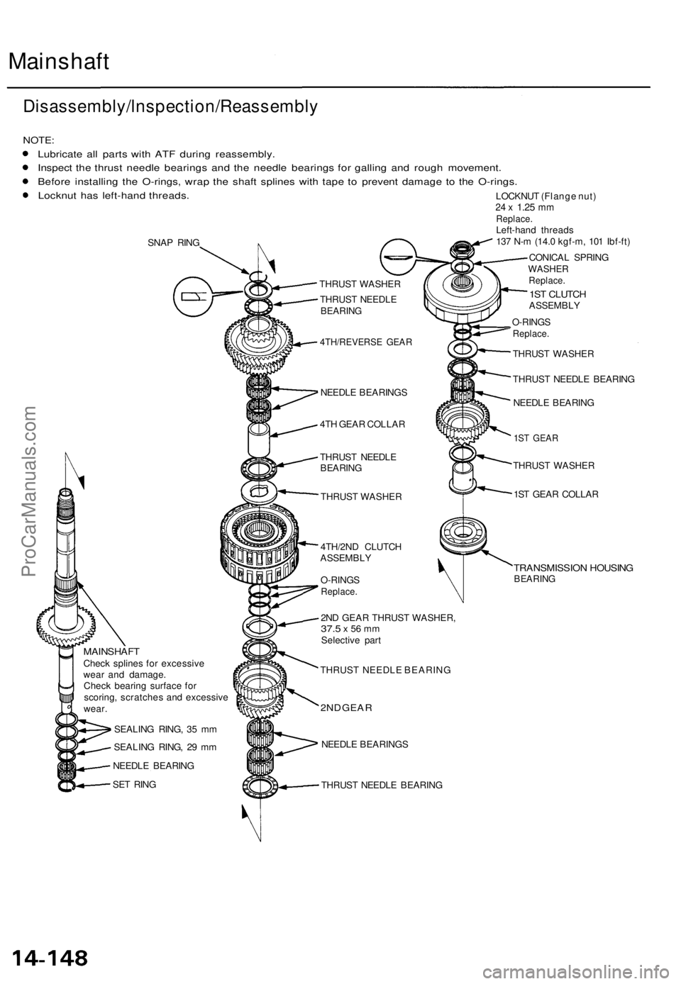
Lubricat e al l part s wit h AT F durin g reassembly .
Inspec t th e thrus t needl e bearing s an d th e needl e bearing s fo r gallin g an d roug h movement .
Befor e installin g th e O-rings , wra p th e shaf t spline s wit h tap e t o preven t damag e t o th e O-rings .
Locknu t ha s left-han d threads .
SNAP RIN G
MAINSHAF TCheck spline s fo r excessiv e
wea r an d damage .
Chec k bearin g surfac e fo r
scoring , scratche s an d excessiv e
wear .
SEALIN G RING , 3 5 m m
SEALIN G RING , 2 9 m m
NEEDL E BEARIN G
SE T RIN G THRUS
T WASHE R
THRUS T NEEDL E
BEARIN G
4TH/REVERS E GEA R
NEEDL E BEARING S
4T H GEA R COLLA R
THRUS T NEEDL E
BEARIN G
THRUS T WASHE R
4TH/2N D CLUTC H
ASSEMBL Y
O-RING S
Replace .
2ND GEA R THRUS T WASHER ,37.5 x 56 m mSelectiv e par t
THRUS T NEEDL E BEARIN G
2ND GEA R
NEEDL E BEARING S
THRUS T NEEDL E BEARIN G LOCKNU
T (Flang e nut )
24 x 1.2 5 mmReplace .Left-hand thread s
13 7 N- m (14. 0 kgf-m , 10 1 Ibf-ft )
CONICA L SPRIN G
WASHE RReplace .
1ST CLUTC HASSEMBL Y
O-RING S
Replace .
THRUST WASHE R
THRUS T NEEDL E BEARIN G
NEEDL E BEARIN G
1ST GEA R
THRUS T WASHE R
1S T GEA R COLLA R
TRANSMISSIO N HOUSIN GBEARING
ProCarManuals.com
Page 1040 of 1771
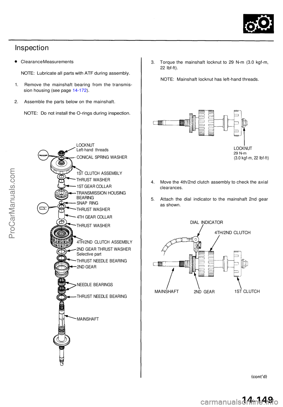
Inspection
Clearanc e Measurement s
NOTE: Lubricat e al l part s wit h AT F durin g assembly .
1. Remov e th e mainshaf t bearin g fro m th e transmis -
sio n housin g (se e pag e 14-172 ).
2 . Assembl e th e part s belo w o n th e mainshaft .
NOTE: D o no t instal l th e O-ring s durin g inspection .
LOCKNUT
Left-han d thread s
- CONICA L SPRIN G WASHE R
1S T CLUTC H ASSEMBL Y
THRUS T WASHE R
1S T GEA R COLLA R
TRANSMISSIO N HOUSIN GBEARING
SNAP RIN G
THRUS T WASHE R
4T H GEA R COLLA R
THRUS T WASHE R
4TH/2N D CLUTC H ASSEMBL Y
2N D GEA R THRUS T WASHE R
Selective par t
THRUS T NEEDL E BEARIN G
2N D GEA R
NEEDL E BEARING S
THRUS T NEEDL E BEARIN G
MAINSHAF T
3. Torqu e th e mainshaf t locknu t t o 2 9 N- m (3. 0 kgf-m ,
22 Ibf-ft) .
NOTE: Mainshaf t locknu t ha s left-han d threads .
LOCKNU T29 N- m(3.0 kgf-m , 2 2 Ibf-ft )
4. Mov e th e 4th/2n d clutc h assembl y t o chec k th e axia l
clearances .
5. Attac h th e dia l indicato r t o th e mainshaf t 2n d gea r
a s shown .
DIAL INDICATO R
4TH/2ND CLUTC H
MAINSHAF T2ND GEA R1ST CLUTC H
ProCarManuals.com
Page 1043 of 1771
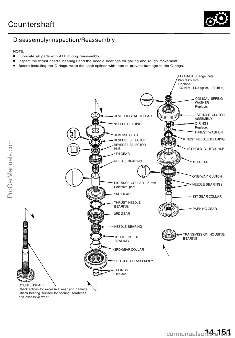
Countershaft
Disassembly/lnspection/Reassembl y
NOTE:
Lubricat e al l part s wit h AT F during reassembly .
Inspec t th e thrus t needl e bearing s an d th e needl e bearing s fo r gallin g an d roug h movement .
Befor e installin g th e O-rings , wra p th e shaf t spline s wit h tap e t o preven t damag e t o th e O-rings .
COUNTERSHAF T
Chec k spline s fo r excessiv e wea r an d damage .
Chec k bearin g surfac e fo r scoring , scratche s
an d excessiv e wear . REVERS
E GEA R COLLA R
NEEDL E BEARIN G
REVERS E GEA R
REVERS E SELECTO R
REVERSE SELECTO RHUB
4TH GEA R
NEEDL E BEARIN G
DISTANC E COLLAR , 3 5 m m
Selectiv e par t
2N D GEA R
THRUS T NEEDL E
BEARIN G
3R D GEA R
NEEDL E BEARIN G
THRUS T NEEDL E
BEARIN G
3R D GEA R COLLA R
3R D CLUTC H ASSEMBL Y
O-RING S
Replace .
LOCKNU T (Flang e nut )24 x 1.2 5 mmReplace .
13 7 N- m (14. 0 kgf-m , 10 1 Ibf-ft )
CONICA L SPRIN G
WASHE RReplace .
1ST-HOL D CLUTC H
ASSEMBL Y
O-RING S
Replace .
THRUST WASHE R
THRUS T NEEDL E BEARIN G
1ST-HOL D CLUTC H HU B
1S T GEA R
ONE-WA Y CLUTC H
NEEDL E BEARING S
1S T GEA R COLLA R
PARKIN G GEA R
TRANSMISSIO N HOUSIN GBEARING
ProCarManuals.com