1995 ACURA TL lock
[x] Cancel search: lockPage 830 of 1771
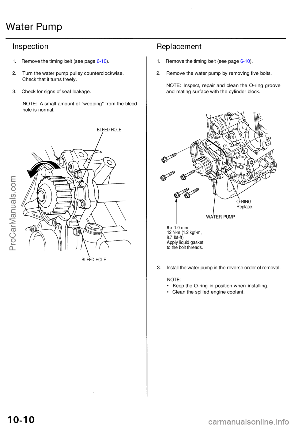
Water Pum p
Inspectio n
1. Remov e th e timin g bel t (se e pag e 6-10 ).
2 . Tur n th e wate r pum p pulle y counterclockwise .
Chec k tha t i t turn s freely .
3 . Chec k fo r sign s o f sea l leakage .
NOTE : A smal l amoun t o f "weeping " fro m th e blee d
hol e is normal .
BLEED HOL E
BLEE D HOL E
Replacemen t
1. Remov e th e timin g bel t (se e pag e 6-10 ).
2 . Remov e th e wate r pum p b y removin g fiv e bolts .
NOTE : Inspect , repai r an d clea n th e O-rin g groov e
an d matin g surfac e wit h th e cylinde r block .
O-RIN GReplace .
WATER PUM P
6 x 1. 0 m m12 N- m (1. 2 kgf-m ,8.7 Ibf-ft )Apply liqui d gaske tto th e bol t threads .
3. Instal l th e wate r pum p in th e revers e orde r o f removal .
NOTE:
• Kee p th e O-rin g i n positio n whe n installing .
• Clea n th e spille d engin e coolant .
ProCarManuals.com
Page 865 of 1771
Troubleshooting
Troubleshooting Procedure s (cont'd )
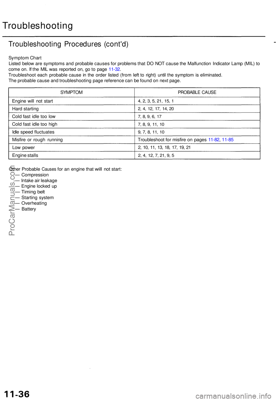
Sympto m Char t
Liste d belo w ar e symptom s an d probabl e cause s fo r problem s tha t D O NO T caus e th e Malfunctio n Indicato r Lam p (MIL ) t o
com e on . I f th e MI L wa s reporte d on , g o to pag e 11-32 .
Troubleshoo t eac h probabl e caus e in th e orde r liste d (fro m lef t t o right ) unti l th e sympto m is eliminated .
Th e probabl e caus e an d troubleshootin g pag e referenc e ca n b e foun d o n nex t page .
SYMPTO M
Engin e wil l no t star t
Har d startin g
Col d fas t idl e to o lo w
Col d fas t idl e to o hig h
Idl e spee d fluctuate s
Misfir e o r roug h runnin g
Lo w powe r
Engin e stall s
PROBABL E CAUS E
4, 2 , 3 , 5 , 21 , 15 , 1
2 , 4 , 12 , 17 , 14 , 2 0
7, 8 , 9 , 6 , 1 7
7, 8 , 9 , 11 , 1 0
9, 7 , 8 , 11 , 1 0
Troubleshoo t fo r misfir e o n page s 11-82 , 11-8 5
2, 10 , 11 , 13 , 18 , 17 , 19 , 2 1
2, 4 , 12 , 7 , 21 , 9 , 5
Othe r Probabl e Causes for a n engin e tha t will no t start :
— Compressio n
— Intak e ai r leakag e
— Engin e locke d u p
— Timin g bel t
— Startin g syste m
— Overheatin g
— Batter y
ProCarManuals.com
Page 869 of 1771
Troubleshooting
Troubleshooting Procedure s (cont'd )
Sympto m Char t
Liste d belo w ar e symptom s an d probabl e cause s fo r problem s tha t D O NO T caus e th e Malfunctio n Indicato r Lam p (MIL ) t o
com e on . I f th e MI L wa s reporte d on , g o to pag e 11-32 .
Troubleshoo t eac h probabl e caus e in th e orde r liste d (fro m lef t t o right ) unti l th e sympto m is eliminated .
Th e probabl e caus e an d troubleshootin g pag e referenc e ca n b e foun d o n nex t page .
SYMPTO M
Engin e wil l no t star t
Har d startin g
Col d fas t idl e to o lo w
Col d fas t idl e to o hig h
Idl e spee d fluctuate s
Misfir e o r roug h runnin g
Lo w powe r
Engin e stall s
PROBABL E CAUS E
4, 2 , 3 , 5 , 21 , 15 , 1
2 , 4 , 12 , 17 , 14 , 2 0
7, 8 , 9 , 6 , 1 7
7, 8 , 9 , 11 , 1 0
9, 7 , 8 , 11 , 1 0
Troubleshoo t fo r misfir e o n page s 11-82 , 11-8 5
2, 10 , 11 , 13 , 18 , 17 , 19 , 2 1
2, 4 , 12 , 7 , 21 , 9 , 5
Othe r Probabl e Causes for a n engin e tha t will no t start :
— Compressio n
— Intak e ai r leakag e
— Engin e locke d u p
— Timin g bel t
— Startin g syste m
— Overheatin g
— Batter y
ProCarManuals.com
Page 892 of 1771
Idle Contro l Syste m
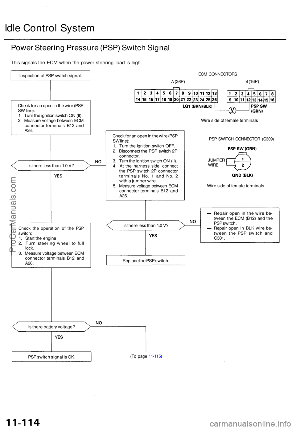
Power Steerin g Pressur e (PSP ) Switc h Signa l
This signal s th e EC M whe n th e powe r steerin g loa d is high .
Is ther e les s tha n 1. 0 V ?
Chec k th e operatio n o f th e PS Pswitch :
1 . Star t th e engin e
2 . Tur n steerin g whee l t o ful l
lock .3. Measur e voltag e betwee n EC M
connecto r terminal s B1 2 an d
A26 .
Is ther e batter y voltage ?
ECM CONNECTOR S
A (26P)B (16P)
Chec k fo r a n ope n in th e wir e (PS P
S W line) :
1 . Tur n th e ignitio n switc h OFF .
2. Disconnec t th e PS P switc h 2 Pconnector .3. Tur n th e ignitio n switc h O N (II) .
4 . A t th e harnes s side , connec t
th e PS P switc h 2 P connecto r
terminal s No . 1 an d No . 2
wit h a jumpe r wire .5. Measur e voltag e betwee n EC M
connecto r terminal s B1 2 an d
A26 .
Is ther e les s tha n 1. 0 V ? Repai
r ope n i n th e wir e be -
twee n th e EC M (B12 ) an d th e
PS P switch .
Repai r ope n in BL K wir e be -
twee n th e PS P switc h an d
G301 .
(To pag e 11-115 )PSP switc h signa l i s OK . Replac
e th e PS P switch . Wir
e sid e o f femal e terminal s
JUMPERWIRE
PSP SWITC H CONNECTO R (C309 )
Wire side of femal e terminal s
Chec
k fo r a n ope n in th e wir e (PS P
S W line) :1. Tur n th e ignitio n switc h O N (II) .2. Measur e voltag e betwee n EC M
connecto r terminal s B1 2 an d
A26 .
Inspectio n o f PS P switc h signal .
ProCarManuals.com
Page 899 of 1771
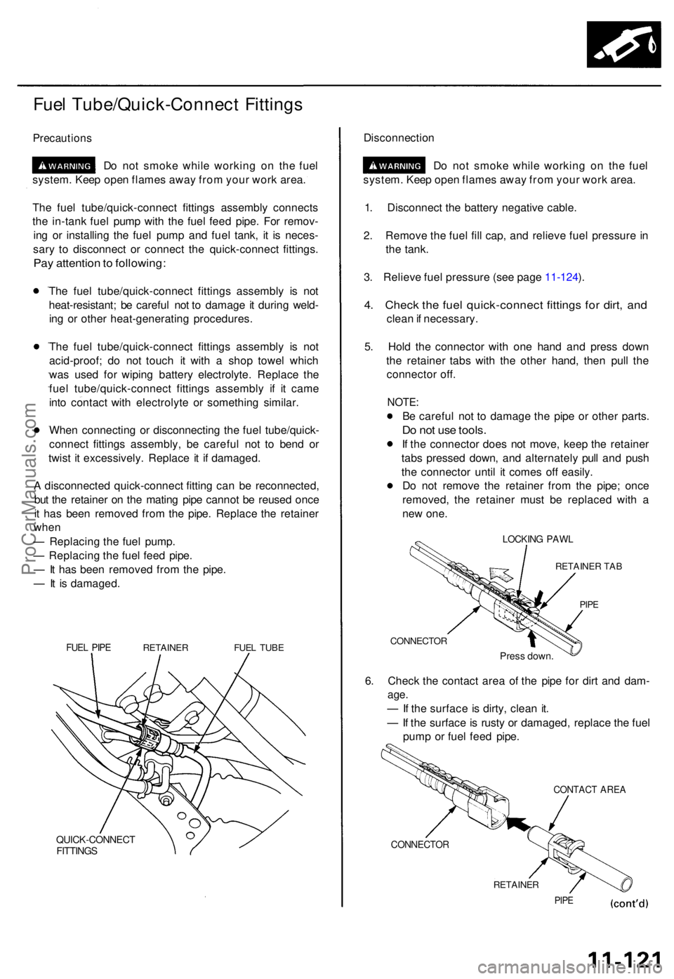
Fuel Tube/Quick-Connec t Fitting s
Precaution s
Do no t smok e whil e workin g o n th e fue l
system . Kee p ope n flame s awa y fro m you r wor k area .
Th e fue l tube/quick-connec t fitting s assembl y connect s
th e in-tan k fue l pum p wit h th e fue l fee d pipe . Fo r remov -
in g o r installin g th e fue l pum p an d fue l tank , i t i s neces -
sar y t o disconnec t o r connec t th e quick-connec t fittings .
Pay attentio n to following :
The fue l tube/quick-connec t fitting s assembl y i s no t
heat-resistant ; b e carefu l no t t o damag e it durin g weld -
in g o r othe r heat-generatin g procedures .
Th e fue l tube/quick-connec t fitting s assembl y i s no t
acid-proof ; d o no t touc h i t wit h a sho p towe l whic h
wa s use d fo r wipin g batter y electrolyte . Replac e th e
fue l tube/quick-connec t fitting s assembl y i f i t cam e
int o contac t wit h electrolyt e o r somethin g similar .
Whe n connectin g o r disconnectin g th e fue l tube/quick -
connec t fitting s assembly , b e carefu l no t t o ben d o r
twis t i t excessively . Replac e i t i f damaged .
A disconnecte d quick-connec t fittin g ca n b e reconnected ,
bu t th e retaine r o n th e matin g pip e canno t b e reuse d onc e
i t ha s bee n remove d fro m th e pipe . Replac e th e retaine r
whe n
— Replacin g th e fue l pump .
— Replacin g th e fue l fee d pipe .
— It ha s bee n remove d fro m th e pipe .
— It i s damaged .
FUEL PIP ERETAINE RFUEL TUB E
QUICK-CONNEC TFITTINGS
Disconnectio n
Do no t smok e whil e workin g o n th e fue l
system . Kee p ope n flame s awa y fro m you r wor k area .
1 . Disconnec t th e batter y negativ e cable .
2 . Remov e th e fue l fil l cap , an d reliev e fue l pressur e in
th e tank .
3 . Reliev e fue l pressur e (se e pag e 11-124 ).
4 . Chec k th e fue l quick-connec t fitting s fo r dirt , an d
clea n if necessary .
5 . Hol d th e connecto r wit h on e han d an d pres s dow n
th e retaine r tab s wit h th e othe r hand , the n pul l th e
connecto r off .
NOTE :
Be carefu l no t t o damag e th e pip e o r othe r parts .
Do no t us e tools .
If th e connecto r doe s no t move , kee p th e retaine r
tab s presse d down , an d alternatel y pul l an d pus h
th e connecto r unti l i t come s of f easily .
D o no t remov e th e retaine r fro m th e pipe ; onc e
removed , th e retaine r mus t b e replace d wit h a
ne w one .
LOCKIN G PAW L
RETAINE R TA B
PIPE
CONNECTO R
Press down .
6. Chec k th e contac t are a o f th e pip e fo r dir t an d dam -
age.
— If th e surfac e is dirty , clea n it .
— If th e surface is rust y o r damaged , replac e th e fue l
pum p o r fue l fee d pipe .
CONTAC T ARE A
CONNECTO R
RETAINER
PIPE
ProCarManuals.com
Page 901 of 1771
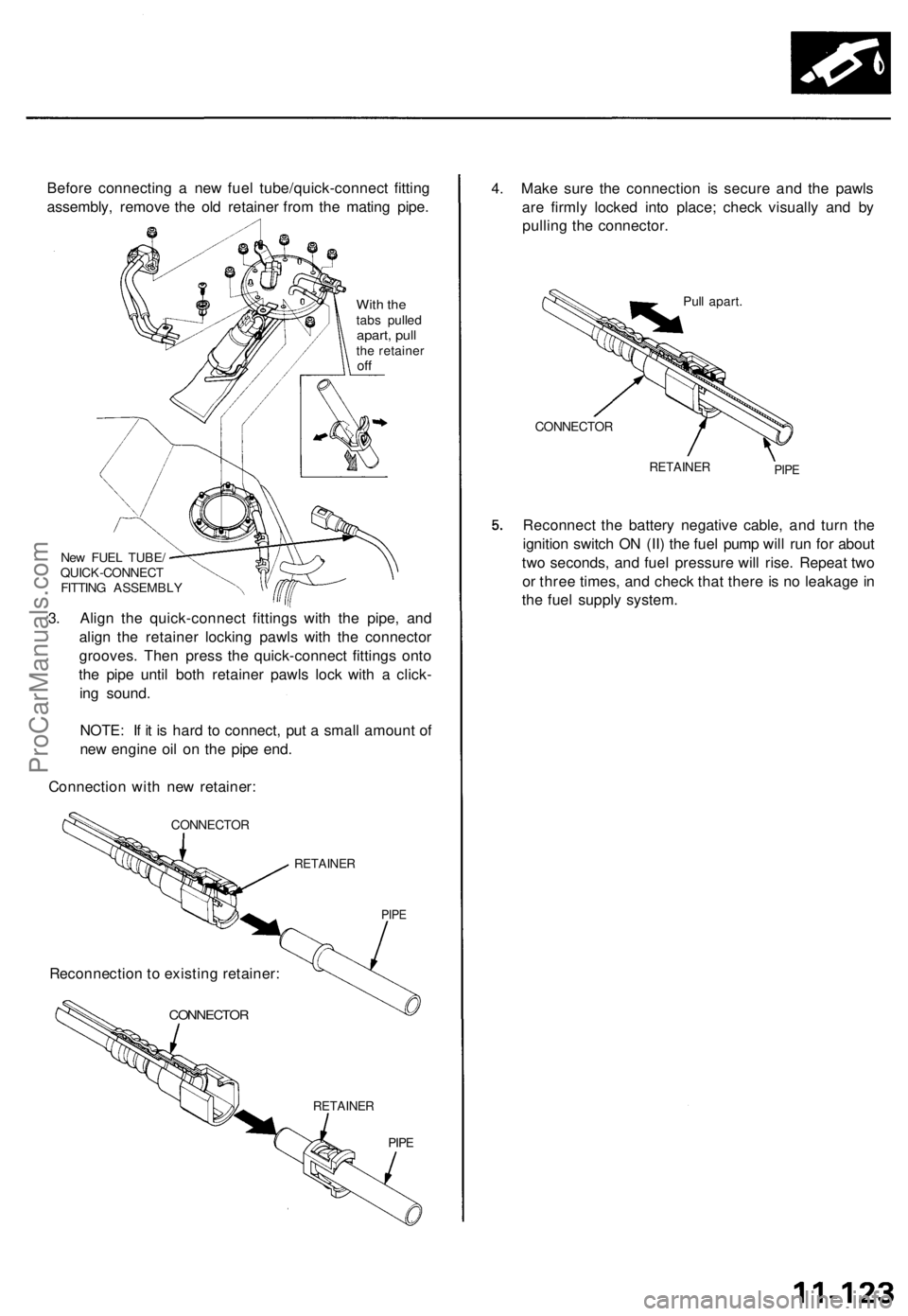
Before connecting a new fuel tube/quick-connect fitting
assembly, remove the old retainer from the mating pipe.
With the
tabs pulled
apart, pull
the retainer
off
New FUEL TUBE/
QUICK-CONNECT
FITTING ASSEMBLY
3. Align the quick-connect fittings with the pipe, and
align the retainer locking pawls with the connector
grooves. Then press the quick-connect fittings onto
the pipe until both retainer pawls lock with a click-
ing sound.
NOTE: If it is hard to connect, put a small amount of
new engine oil on the pipe end.
Connection with new retainer:
CONNECTOR
RETAINER
PIPE
CONNECTOR
RETAINER
PIPE
4. Make sure the connection is secure and the pawls
are firmly locked into place; check visually and by
pulling the connector.
Pull apart.
CONNECTOR
RETAINER
PIPE
Reconnect the battery negative cable, and turn the
ignition switch ON (II) the fuel pump will run for about
two seconds, and fuel pressure will rise. Repeat two
or three times, and check that there is no leakage in
the fuel supply system.
Reconnection to existing retainer:ProCarManuals.com
Page 919 of 1771
Throttle Cable
Inspection/Adjustment
1.
2.
3.
Start the engine. Hold the engine at 3,000 rpm with
no load (transmission in or position) until the
radiator fan comes on, then let it idle.
Check that the throttle cable operates smoothly with
no binding or sticking. Repair as necessary.
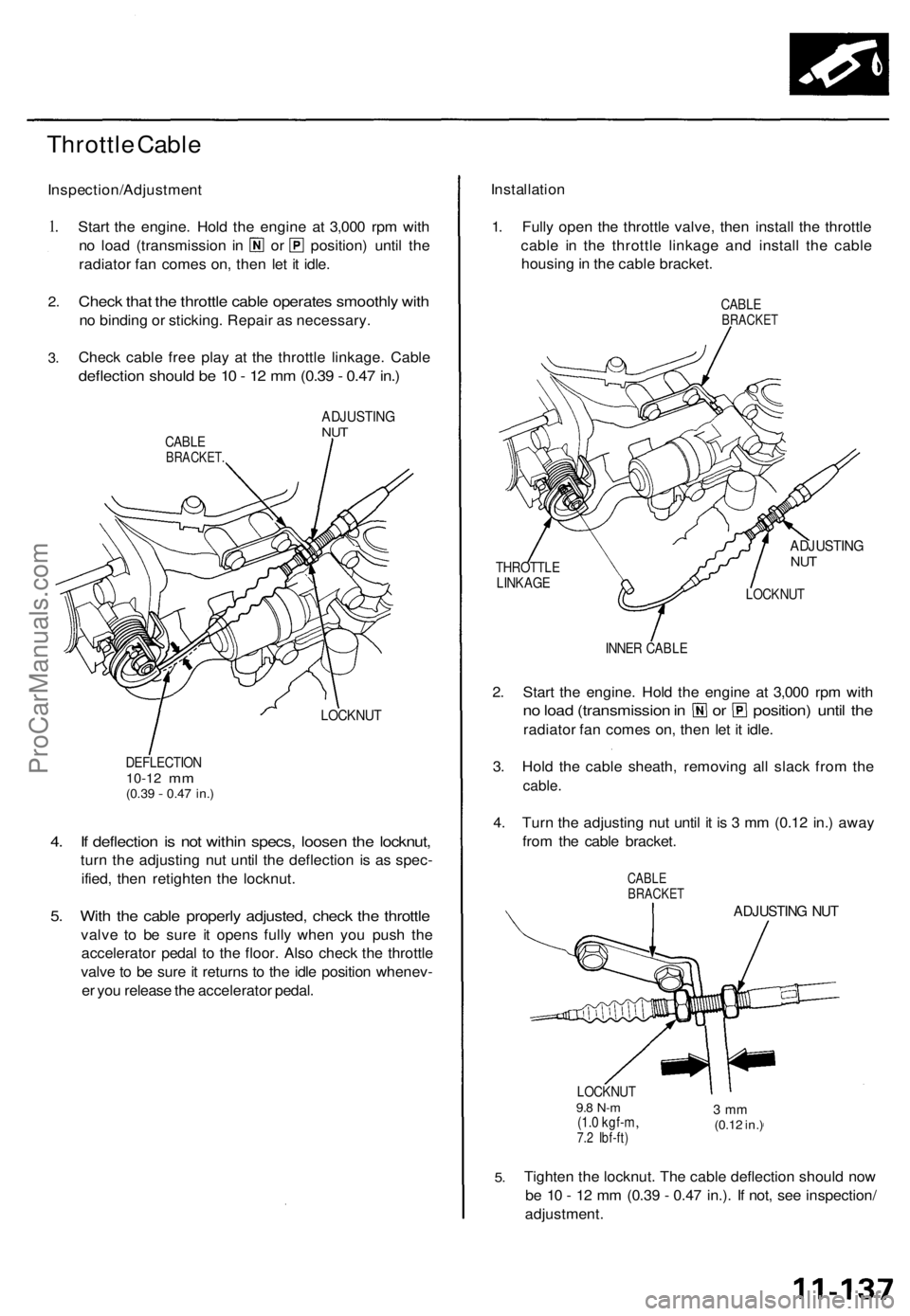
Check cable free play at the throttle linkage. Cable
deflection should be 10 - 12 mm (0.39 - 0.47 in.)
CABLE
BRACKET.
ADJUSTING
NUT
LOCKNUT
DEFLECTION
10-12
mm
(0.39
-
0.47 in.)
4. If deflection is not within specs, loosen the locknut,
turn the adjusting nut until the deflection is as spec-
ified, then retighten the locknut.
5. With the cable properly adjusted, check the throttle
valve to be sure it opens fully when you push the
accelerator pedal to the floor. Also check the throttle
valve to be sure it returns to the idle position whenev-
er you release the accelerator pedal.
Installation
1. Fully open the throttle valve, then install the throttle
cable in the throttle linkage and install the cable
housing in the cable bracket.
CABLE
BRACKET
THROTTLE
LINKAGE
ADJUSTING
NUT
LOCKNUT
INNER CABLE
2. Start the engine. Hold the engine at 3,000 rpm with
no load (transmission in or position) until the
radiator fan comes on, then let it idle.
3. Hold the cable sheath, removing all slack from the
cable.
4. Turn the adjusting nut until it is 3 mm (0.12 in.) away
from the cable bracket.
CABLE
BRACKET
ADJUSTING NUT
LOCKNUT
9.8 N-m
(1.0 kgf-m,
7.2 Ibf-ft)
3 mm
(0.12 in.)
5.
Tighten the locknut. The cable deflection should now
be 10 - 12 mm (0.39 - 0.47 in.). If not, see inspection/
adjustment.ProCarManuals.com
Page 924 of 1771
Intake Ai r Syste m
Intake Ai r Bypas s (IAB ) Contro l Syste m (cont'd )
Troubleshootin g
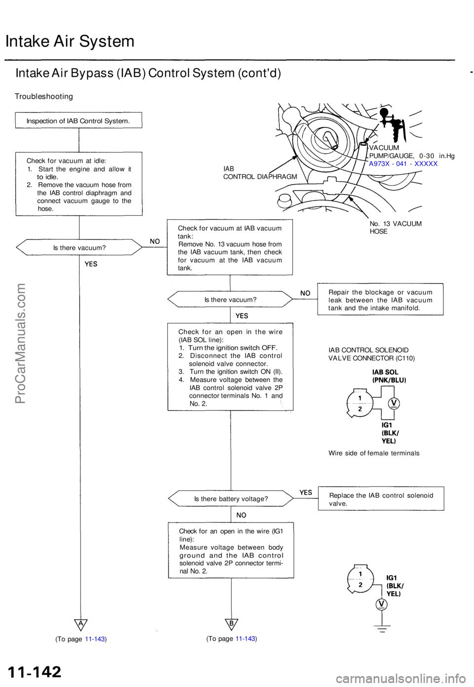
Is ther e vacuum ?
IABCONTRO L DIAPHRAG M
VACUUMPUMP/GAUGE , 0-3 0 in.H g
A973 X - 04 1 - XXXX X
Chec k fo r vacuu m at IA B vacuu m
tank :
Remov e No . 1 3 vacuu m hos e fro m
th e IA B vacuu m tank , the n chec k
fo r vacuu m a t th e IA B vacuu m
tank .
Is ther e vacuum ? Repai
r th e blockag e o r vacuu m
lea k betwee n th e IA B vacuu m
tan k an d th e intak e manifold .
Chec k fo r a n ope n i n th e wir e
(IA B SO L line) :
1. Tur n th e ignitio n switc h OFF .2. Disconnec t th e IA B contro l
solenoi d valv e connector .
3 . Tur n th e ignitio n switc h O N (II) .
4 . Measur e voltag e betwee n th e
IA B contro l solenoi d valv e 2 P
connecto r terminal s No . 1 an d
No. 2 .
IA B CONTRO L SOLENOI D
VALV E CONNECTO R (C110 )
Wir e sid e o f femal e terminal s
I s ther e batter y voltage ? Replac
e th e IA B contro l solenoi d
valve.
Check fo r a n ope n in th e wir e (IG 1line) :Measur e voltag e betwee n bod ygroun d an d th e IA B contro lsolenoid valv e 2 P connecto r termi -nal No . 2 .
(T o pag e 11-143 ) (T
o pag e 11-143 )
Inspectio n o f IA B Contro l System .
Check fo r vacuu m at idle :
1 . Star t th e engin e an d allo w i t
to idle .2. Remov e th e vacuu m hos e fro m
th e IA B contro l diaphrag m an d
connec t vacuu m gaug e t o th e
hose .
No. 1 3 VACUU M
HOSE
ProCarManuals.com