Page 385 of 1771
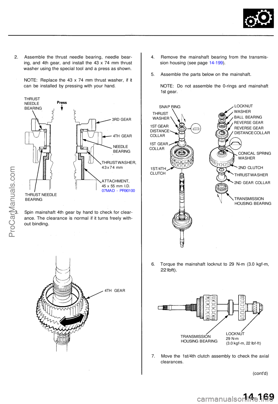
2. Assembl e th e thrus t needl e bearing , needl e bear -
ing , an d 4t h gear , an d instal l th e 4 3 x 7 4 m m thrus t
washe r usin g th e specia l too l an d a pres s a s shown .
NOTE : Replac e th e 4 3 x 7 4 m m thrus t washer , i f i t
ca n b e installe d b y pressin g wit h you r hand .
THRUS TNEEDLEBEARIN G
3RD GEAR
4T H GEA R
NEEDL EBEARIN G
THRUST WASHER ,
43x7 4 m m
ATTACHMENT ,
45 x 55 m m I.D .07MA D - PR9010 0
THRUS T NEEDL E
BEARIN G
3. Spi n mainshaf t 4t h gea r b y han d t o chec k fo r clear -
ance . Th e clearanc e i s norma l i f i t turn s freel y with -
out binding .
4TH GEA R
4. Remov e th e mainshaf t bearin g fro m th e transmis -
sio n housin g (se e pag e 14-199 ).
5 . Assembl e th e part s belo w o n th e mainshaft .
NOTE : D o no t assembl e th e 0-ring s an d mainshaf t
1s t gear .
SNAP RIN G
THRUS TWASHE R
1ST GEA R
DISTANC E
COLLAR
1ST GEA RCOLLA R
1ST/4THCLUTCH
LOCKNU T
WASHER
BALL BEARIN G
REVERS E GEA R
REVERS E GEA RDISTANC E COLLA R
CONICA L SPRIN G
WASHE R
2ND CLUTC H
THRUS T WASHE R
2ND GEA R COLLA R
TRANSMISSIO N
HOUSIN G BEARIN G
6. Torqu e th e mainshaf t locknu t t o 2 9 N- m (3. 0 kgf-m ,
22 Ibft) .
TRANSMISSIO N
HOUSIN G BEARIN GLOCKNU T29 N- m(3.0 kgf-m , 2 2 Ibf-ft )
7. Mov e th e 1st/4t h clutc h assembl y t o chec k th e axia l
clearances .
(cont'd)
ProCarManuals.com
Page 388 of 1771
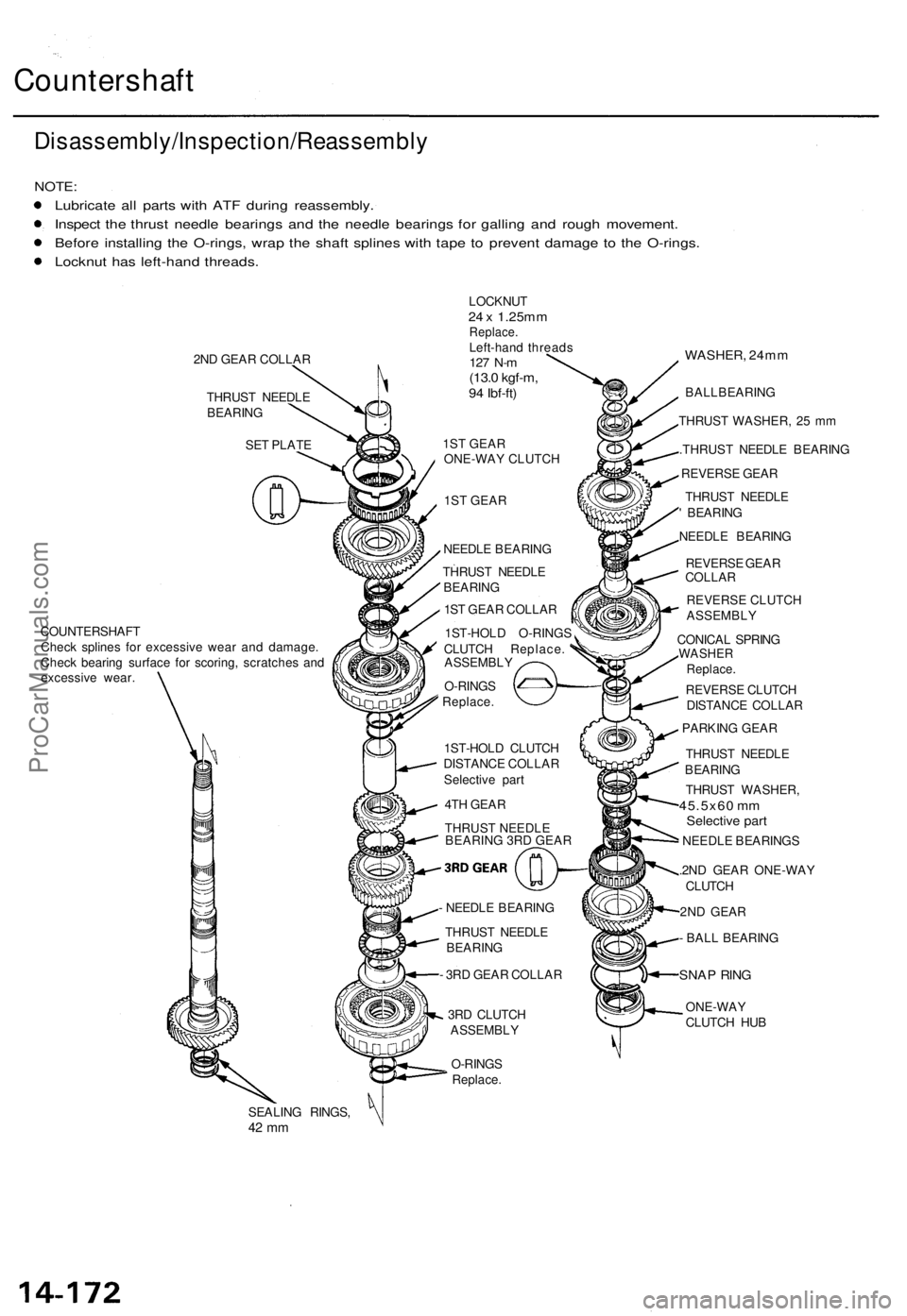
Countershaft
Disassembly/Inspection/Reassembl y
NOTE:
Lubricat e al l part s wit h AT F durin g reassembly .
Inspec t th e thrus t needl e bearing s an d th e needl e bearing s fo r gallin g an d roug h movement .
Befor e installin g th e O-rings , wra p th e shaf t spline s wit h tap e t o preven t damag e t o th e O-rings .
Locknu t ha s left-han d threads .
COUNTERSHAF T
Chec k spline s fo r excessiv e wea r an d damage .
Chec k bearin g surfac e fo r scoring , scratche s an d
excessiv e wear .
SEALING RINGS ,
42 m m
LOCKNU T24 x 1.25m mReplace .Left-hand thread s127 N- m(13. 0 kgf-m ,94 Ibf-ft )
1ST GEAR ONE-WAY CLUTCH
1ST GEAR
NEEDL E BEARIN G
THRUS T NEEDL E
BEARIN G
1S T GEA R COLLA R
1ST-HOL D O-RING S
CLUTC H Replace .
ASSEMBL Y
O-RING S
Replace .
1ST-HOL D CLUTC H
DISTANC E COLLA R
Selectiv e par t
4T H GEA R
THRUST NEEDLE BEARING 3RD GEAR
- NEEDL E BEARIN G
THRUS T NEEDL E
BEARIN G
- 3R D GEA R COLLA R
3R D CLUTC H
ASSEMBL Y
O-RING S
Replace .
WASHER , 24m m
BALLBEARIN G
THRUS T WASHER , 2 5 m m
.THRUS T NEEDL E BEARIN G
REVERS E GEA R
THRUS T NEEDL E
' BEARIN G
NEEDL E BEARIN G
REVERS E GEA R
COLLA R
REVERSE CLUTCH
ASSEMBLY
CONICA L SPRIN G
WASHE RReplace.
REVERS E CLUTC H
DISTANC E COLLA R
PARKIN G GEA R
THRUS T NEEDL E
BEARIN G
THRUS T WASHER ,
45.5x60 m mSelectiv e par t
NEEDL E BEARING S
.2N D GEA R ONE-WA Y
CLUTC H
2N D GEA R
- BAL L BEARIN G
SNAP RIN G
ONE-WA Y
CLUTC H HU B
2N
D GEA R COLLA R
THRUS T NEEDL E
BEARIN G
SE T PLAT E
ProCarManuals.com
Page 389 of 1771
Inspection
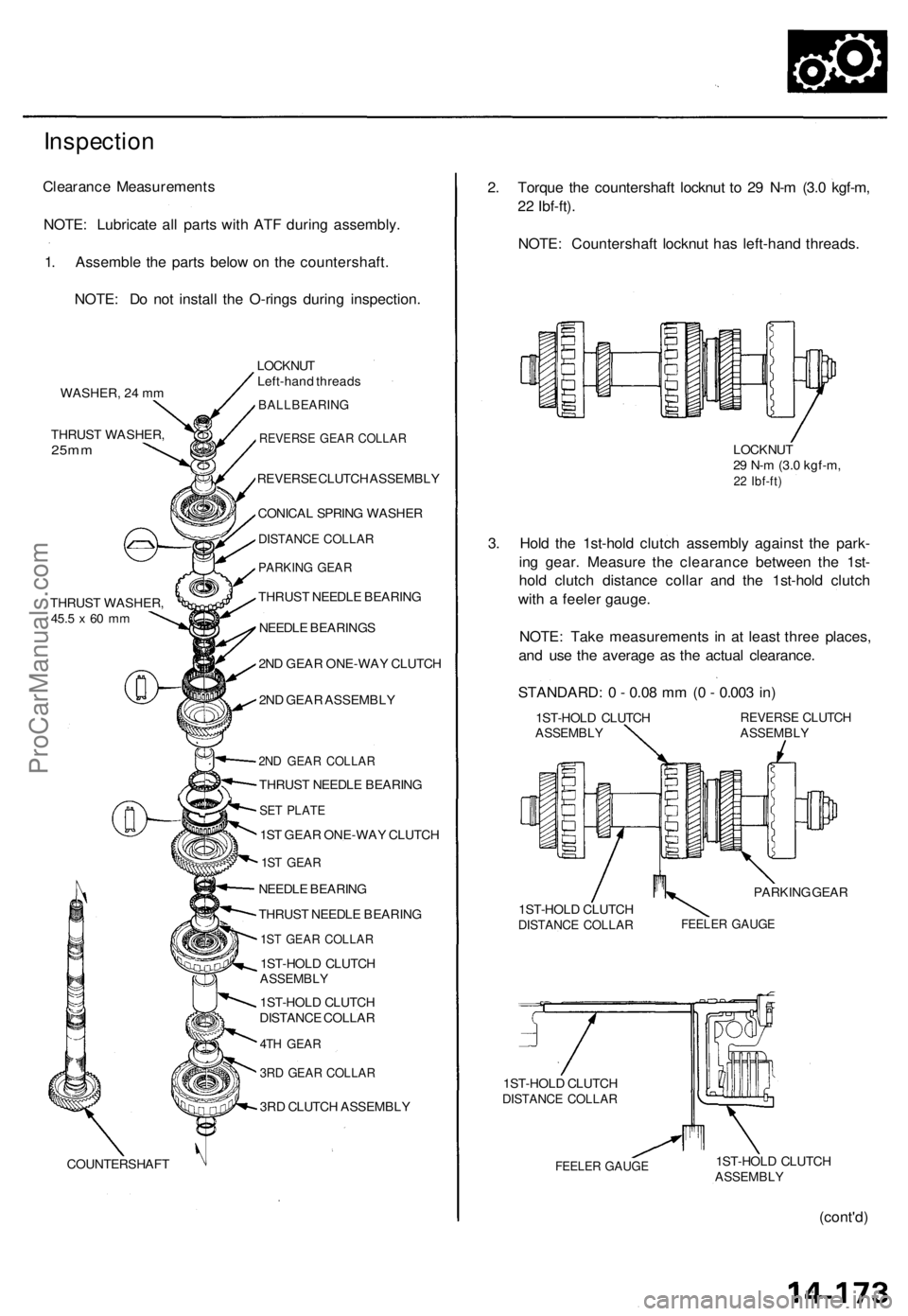
Clearance Measurements
NOTE: Lubricate all parts with ATF during assembly.
1. Assemble the parts below on the countershaft.
NOTE: Do not install the O-rings during inspection.
WASHER, 24 mm
THRUST WASHER,
25mm
THRUST WASHER,
45.5
x 60 mm
COUNTERSHAFT
LOCKNUT
Left-hand threads
BALLBEARING
REVERSE GEAR COLLAR
REVERSE CLUTCH ASSEMBLY
CONICAL SPRING WASHER
DISTANCE COLLAR
PARKING GEAR
THRUST NEEDLE BEARING
NEEDLE BEARINGS
2ND GEAR ONE-WAY CLUTCH
2ND GEAR ASSEMBLY
2ND GEAR COLLAR
THRUST NEEDLE BEARING
SET PLATE
1ST GEAR ONE-WAY CLUTCH
1ST GEAR
NEEDLE BEARING
THRUST NEEDLE BEARING
1ST GEAR COLLAR
1ST-HOLD CLUTCH
ASSEMBLY
1ST-HOLD CLUTCH
DISTANCE COLLAR
4TH GEAR
3RD GEAR COLLAR
3RD CLUTCH ASSEMBLY
2. Torque the countershaft locknut to 29 N-m (3.0 kgf-m,
22 Ibf-ft).
NOTE: Countershaft locknut has left-hand threads.
LOCKNUT
29 N-m (3.0 kgf-m,
22 Ibf-ft)
3. Hold the 1st-hold clutch assembly against the park-
ing gear. Measure the clearance between the 1st-
hold clutch distance collar and the 1st-hold clutch
with a feeler gauge.
NOTE: Take measurements in at least three places,
and use the average as the actual clearance.
STANDARD: 0 - 0.08 mm (0 - 0.003 in)
1ST-HOLD CLUTCH
ASSEMBLY
REVERSE CLUTCH
ASSEMBLY
PARKING GEAR
1ST-HOLD CLUTCH
DISTANCE COLLAR
FEELER GAUGE
1ST-HOLD CLUTCH
DISTANCE COLLAR
FEELER GAUGE
1ST-HOLD CLUTCH
ASSEMBLY
(cont'd)ProCarManuals.com
Page 414 of 1771
A/T Gea r Positio n Switc h
Remova l
1. Shif t th e deten t leve r t o th e position .
CONTROL SHAF T
LOC K WASHE R
Replace .
DETENTLEVER
LOCKNU T A/
T GEA R POSITIO N
SWITC H
2. Pr y th e locktab s o n th e loc k washer , the n remov e
th e locknu t an d loc k washer .
3 . Remov e th e bolt s securin g th e A/ T gea r positio n
switch , the n remov e th e A/ T gea r positio n switch .
ProCarManuals.com
Page 416 of 1771
A/T Gea r Positio n Switc h
Installatio n (cont'd )
3. Instal l th e A/ T gea r positio n switc h o n th e contro l
shaft, the n instal l th e bolt s loosely .
CONTRO L SHAF T
6 x 1.0 mm BOLTS
Tighte n loosely . A/
T GEA R POSITIO N
SWITC H
4. Instal l a ne w loc k washe r o n th e A/ T gea r positio n
switch b y alignin g it s projecte d ti p wit h th e posi -
tio n mar k o n th e A/ T gea r positio n switc h a s shown .
POSITIO N A/T GEAR POSITIO NMARK SWITC H
6x1.0 mm12 N- m (1. 2 kgf-m ,
8. 7 Ibf-ft )
LOC K TAB S
LEVE R
LOCKNU T
1 2 N- m (1. 2 kgf-m ,
8. 7 Ibf-ft ) CONTRO
L
SHAF T
5. Tighte n th e locknu t whil e holdin g th e deten t leve r i n
th e position , the n ben d th e loc k tab s agains t th e
locknut .
6 . Tighte n th e 6 m m bolt s t o th e specifie d torque .
ProCarManuals.com
Page 417 of 1771
Transmission
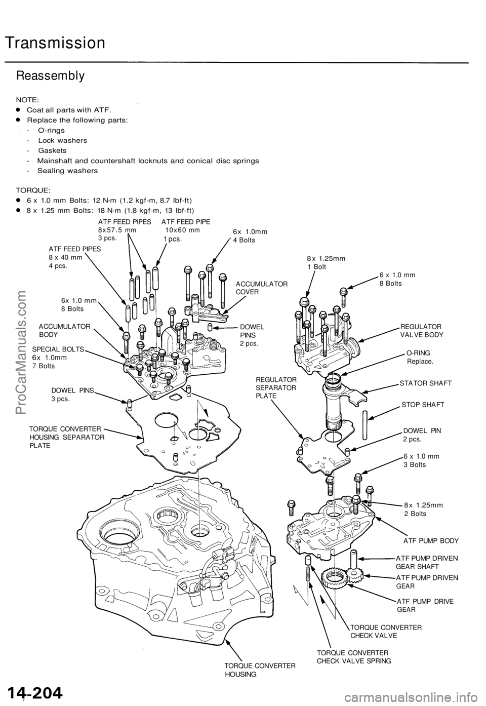
Reassembly
NOTE:
Coat al l part s wit h ATF .
Replac e th e followin g parts :
- O-ring s
- Loc k washer s
- Gasket s
- Mainshaf t an d countershaf t locknut s an d conica l dis c spring s
- Sealin g washer s
TORQUE :
6 x 1. 0 m m Bolts : 1 2 N- m (1. 2 kgf-m , 8. 7 Ibf-ft )
8 x 1.2 5 m m Bolts : 1 8 N- m (1. 8 kgf-m , 1 3 Ibf-ft )
ATF FEE D PIPE S AT F FEE D PIP E
8x57. 5 m m 10x6 0 m m
3 pcs .
ATF FEE D PIPE S8 x 4 0 m m4 pcs .
6x 1. 0 m m8 Bolt s
ACCUMULATO R
BODY
SPECIA L BOLT S6x 1.0m m7 Bolt s
DOWE L PIN S
3 pcs.
TORQU E CONVERTE R
HOUSIN G SEPARATO R
PLATE
6x 1.0m m' 4 Bolt s
8x 1.25m m1 Bol t6 x 1. 0 m m8 Bolt s
REGULATO RSEPARATO RPLATE
REGULATO RVALVE BOD Y
O-RIN G
Replace .
STATOR SHAFT
STOP SHAFT
DOWE L PI N
2 pcs .
6 x 1. 0 m m3 Bolt s
8x 1.25m m2 Bolt s
AT F PUM P BOD Y
ATF PUM P DRIVE NGEAR SHAF T
ATF PUM P DRIVE NGEAR
ATF PUM P DRIV EGEAR
TORQU E CONVERTE R
CHEC K VALV E
TORQU E CONVERTE R
HOUSING
TORQUE CONVERTE R
CHEC K VALV E SPRIN G
1 pcs.
ACCUMULATO RCOVER
DOWE LPINS2 pcs .
ProCarManuals.com
Page 421 of 1771
Transmission
Reassembly (cont'd )
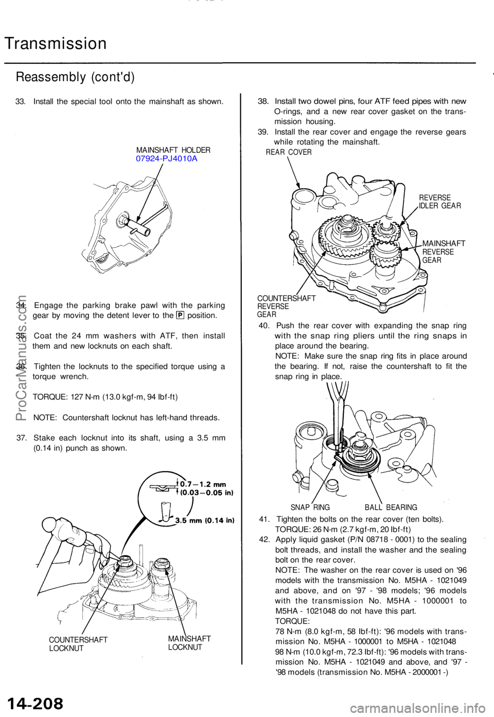
33. Instal l th e specia l too l ont o th e mainshaf t a s shown .
MAINSHAF T HOLDE R07924-PJ4010 A
34. Engag e th e parkin g brak e paw l wit h th e parkin g
gear b y movin g th e deten t leve r t o th e position .
35 . Coa t th e 2 4 m m washer s wit h ATF , the n instal l
the m an d ne w locknut s o n eac h shaft .
36 . Tighte n th e locknut s t o th e specifie d torqu e usin g a
torqu e wrench .
TORQUE : 12 7 N- m (13. 0 kgf-m , 9 4 Ibf-ft )
NOTE : Countershaf t locknu t ha s left-han d threads .
37 . Stak e eac h locknu t int o it s shaft , usin g a 3. 5 m m
(0.1 4 in ) punc h a s shown .
COUNTERSHAF TLOCKNUT
MAINSHAF TLOCKNUT
38. Instal l tw o dowe l pins , fou r AT F fee d pipe s wit h ne w
O-rings , an d a ne w rea r cove r gaske t o n th e trans -
missio n housing .
39 . Instal l th e rea r cove r an d engag e th e revers e gear s
whil e rotatin g th e mainshaft .
REAR COVE R
REVERS EIDLER GEA R
MAINSHAF TREVERSEGEAR
COUNTERSHAF TREVERSEGEAR
40. Pus h th e rea r cove r wit h expandin g th e sna p rin g
with th e sna p rin g plier s unti l th e rin g snap s i n
plac e aroun d th e bearing .
NOTE : Mak e sur e th e sna p rin g fit s i n plac e aroun d
th e bearing . I f not , rais e th e countershaf t t o fi t th e
sna p rin g i n place .
SNAP RIN G BAL L BEARIN G
41. Tighte n th e bolt s o n th e rea r cove r (te n bolts) .
TORQUE : 2 6 N- m (2. 7 kgf-m , 2 0 Ibf-ft )
42 . Appl y liqui d gaske t (P/ N 0871 8 - 0001 ) t o th e sealin g
bol t threads , an d instal l th e washe r an d th e sealin g
bol t o n th e rea r cover .
NOTE : Th e washe r o n th e rea r cove r i s use d o n '9 6
model s wit h th e transmissio n No . M5H A - 102104 9
an d above , an d o n '9 7 - '9 8 models ; '9 6 model s
wit h th e transmissio n No . M5H A - 100000 1 t o
M5H A - 102104 8 d o no t hav e thi s part .
TORQUE :
78 N- m (8. 0 kgf-m , 5 8 Ibf-ft) : '9 6 model s wit h trans -
missio n No . M5H A - 100000 1 t o M5H A - 102104 8
9 8 N- m (10. 0 kgf-m , 72. 3 Ibf-ft) : '9 6 model s wit h trans -
missio n No . M5H A - 102104 9 an d above , an d '9 7 -
'9 8 model s (transmissio n No . M5H A - 200000 1 -)
ProCarManuals.com
Page 427 of 1771
Transmission
Installation (cont'd )
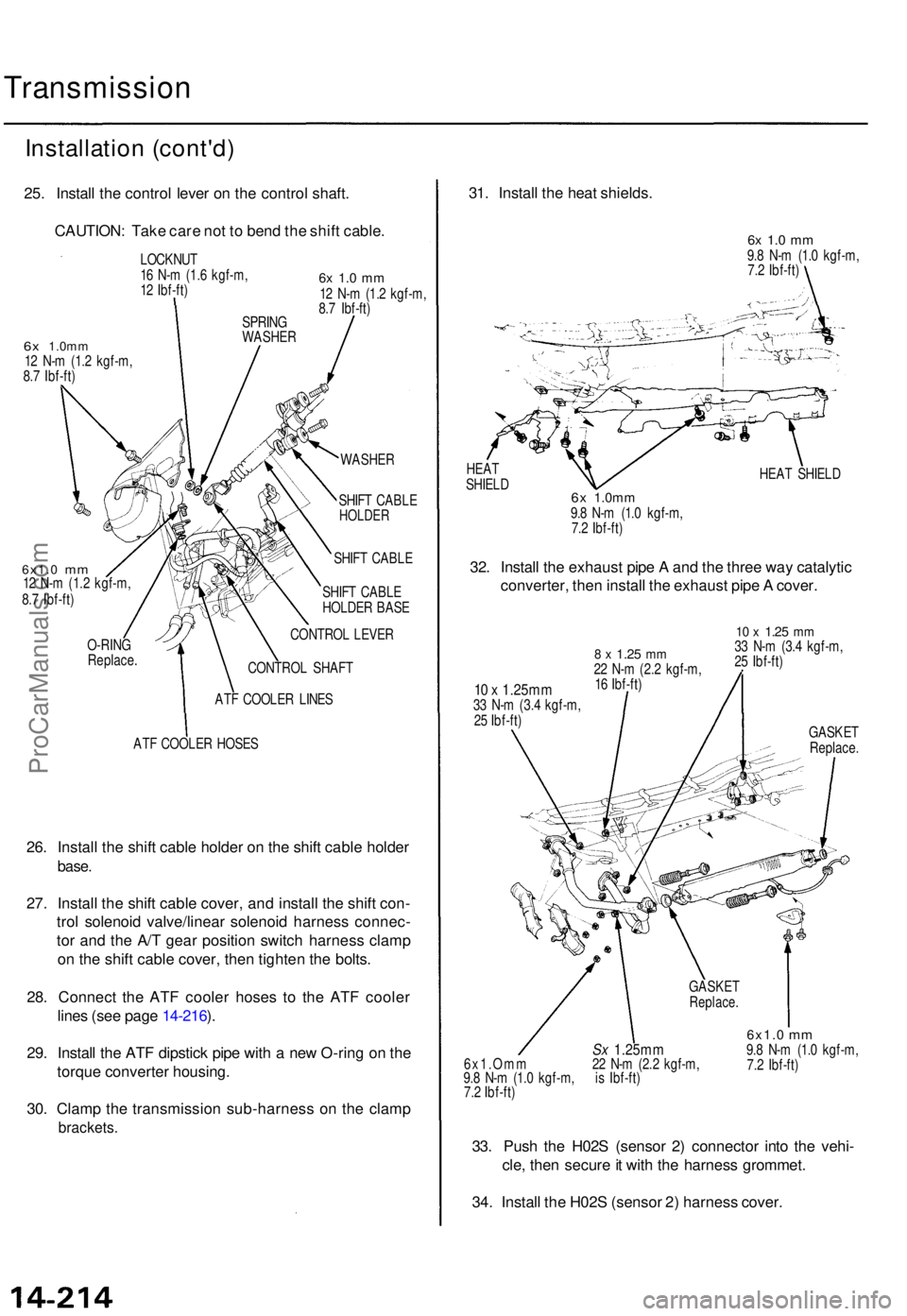
25. Instal l th e contro l leve r o n th e contro l shaft .
CAUTION : Tak e car e no t t o ben d th e shif t cable .
LOCKNU T
1 6 N- m (1. 6 kgf-m ,
1 2 Ibf-ft )
6x 1.0m m12 N- m (1. 2 kgf-m ,
8. 7 Ibf-ft )
6x 1. 0 m m12 N- m (1. 2 kgf-m ,
8. 7 Ibf-ft )
WASHE R
6x1.0 mm12 N- m (1.2 kgf-m ,
8. 7 Ibf-ft )
O-RIN G
Replac e SHIF
T CABL E
SHIF T CABL E
HOLDE R BAS E
CONTRO L LEVE R
CONTRO L SHAF T
AT F COOLE R LINE S
AT F COOLE R HOSE S
26. Instal l th e shif t cabl e holde r o n th e shif t cabl e holde r
base.
27. Instal l th e shif t cabl e cover , an d instal l th e shif t con -
tro l solenoi d valve/linea r solenoi d harnes s connec -
to r an d th e A/ T gea r positio n switc h harnes s clam p
o n th e shif t cabl e cover , the n tighte n th e bolts .
28 . Connec t th e AT F coole r hose s t o th e AT F coole r
line s (se e pag e 14-216 ).
29 . Instal l th e AT F dipstic k pip e wit h a ne w O-rin g o n th e
torqu e converte r housing .
30 . Clam p th e transmissio n sub-harnes s o n th e clam p
brackets .
31. Instal l th e hea t shields .
6x 1. 0 m m9.8 N- m (1. 0 kgf-m ,
7. 2 Ibf-ft )
HEA T SHIEL D
32. Instal l th e exhaus t pip e A an d th e thre e wa y catalyti c
converter , the n instal l th e exhaus t pip e A cover .
10 x 1.25m m33 N- m (3. 4 kgf-m ,
2 5 Ibf-ft )
8 x 1.2 5 mm22 N- m (2. 2 kgf-m ,
1 6 Ibf-ft )
10 x 1.2 5 mm33 N- m (3. 4 kgf-m ,
2 5 Ibf-ft )
GASKE T
Replace .
Sx 1.25m m6x1.Om m 2 2 N- m (2. 2 kgf-m ,
9. 8 N- m (1. 0 kgf-m , i s Ibf-ft )
7. 2 Ibf-ft )
6x1.0 mm9.8 N- m (1. 0 kgf-m ,
7. 2 Ibf-ft )
33. Pus h th e H02 S (senso r 2 ) connecto r int o th e vehi -
cle , the n secur e it wit h th e harnes s grommet .
34 . Instal l th e H02 S (senso r 2 ) harnes s cover .
SPRIN G
WASHE R
SHIFT CABL E
HOLDE R
GASKE TReplace .
6x 1.0m m9.8 N- m (1. 0 kgf-m ,
7. 2 Ibf-ft )
HEA
T
SHIEL D
ProCarManuals.com