Page 430 of 1771
Shift Cabl e
Replacemen t
Make sur e lifts , jack s an d safet y stand s ar e place d
properly , an d hois t bracket s ar e attache d to th e cor -
rec t positio n o n th e engin e (se e sectio n 1) .
Appl y parkin g brake , an d bloc k rea r wheel s s o th e
vehicl e wil l no t rol l of f stand s an d fal l o n yo u whil e
workin g unde r it .
1 . Rais e th e fron t o f th e vehicle , an d suppor t i t wit h
safet y stand s (se e sectio n 1 ).
2 . Se t parkin g brake , an d bloc k bot h rea r wheel s
securely .
3. Shif t th e transmissio n int o th e position .
4 . Remov e th e cente r consol e (se e sectio n 20 ).
5 . Shif t th e transmissio n int o th e position .
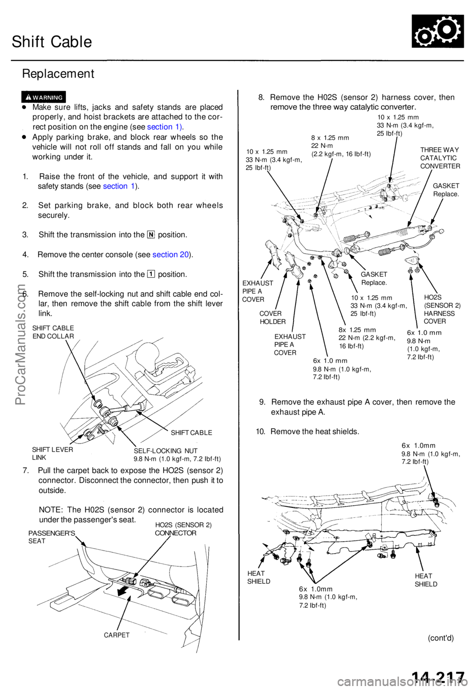
6 . Remov e th e self-lockin g nu t an d shif t cabl e en d col -
lar , the n remov e th e shif t cabl e fro m th e shif t leve r
link .
SHIF T CABL E
EN D COLLA R
SHIF T LEVE R
LIN K SHIF
T CABL E
SELF-LOCKIN G NU T
9. 8 N- m (1. 0 kgf-m , 7. 2 Ibf-ft )
7. Pul l th e carpe t bac k t o expos e th e HO2 S (senso r 2 )
connector . Disconnec t th e connector , the n pus h it t o
outside .
NOTE : Th e H02 S (senso r 2 ) connecto r i s locate d
unde r th e passenger' s seat .
PASSENGER' SSEAT
HO2S (SENSO R 2 )CONNECTO R
CARPET
8. Remov e th e H02 S (senso r 2 ) harnes s cover , the n
remov e th e thre e wa y catalyti c converter .
10 x 1.2 5 mm33 N- m (3. 4 kgf-m ,
2 5 Ibf-ft )
10 x 1.2 5 mm33 N- m (3. 4 kgf-m ,25 Ibf-ft )
8 x 1.2 5 mm22 N- m(2.2 kgf-m , 1 6 Ibf-ft ) THRE
E WA YCATALYTI CCONVERTE R
GASKE T
Replace .
EXHAUS T
PIPE ACOVE R
COVE R
HOLDE R
10 x 1.2 5 mm33 N- m (3. 4 kgf-m ,25 Ibf-ft )
EXHAUS T
PIP E A
COVE R
8x 1.2 5 mm22 N- m (2. 2 kgf-m ,
1 6 Ibf-ft ) HO2
S
(SENSO R 2 )
HARNES S
COVE R
6x 1. 0 m m9.8 N- m (1. 0 kgf-m ,
7. 2 Ibf-ft )
6x 1. 0 m m9.8 N- m(1.0 kgf-m ,
7. 2 Ibf-ft )
9. Remov e th e exhaus t pip e A cover , the n remov e th e
exhaus t pip e A .
10 . Remov e th e hea t shields .
6x 1.0m m9.8 N- m (1. 0 kgf-m ,
7. 2 Ibf-ft )
HEATSHIEL D6x 1.0m m9.8 N- m (1. 0 kgf-m ,
7. 2 Ibf-ft ) HEA
T
SHIEL D
(cont'd )
GASKE T
Replace .
ProCarManuals.com
Page 431 of 1771
Shift Cabl e
Replacemen t (cont'd )
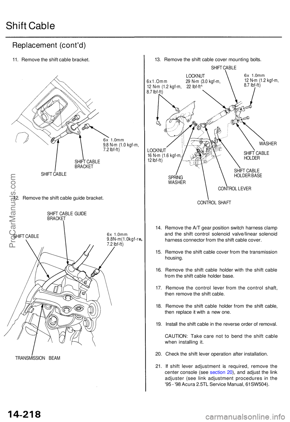
11. Remov e th e shif t cabl e bracket .
6x 1.0m m9.8 N- m (1. 0 kgf-m ,
7. 2 Ibf-ft )
SHIF T CABL E
BRACKE T
SHIFT CABL E
12. Remov e th e shif t cabl e guid e bracket .
SHIFT CABL E GUID EBRACKE T
SHIFT CABL E6x 1.0m m9.8N-m(1.0kgf- r
7. 2 Ibf-ft )
TRANSMISSIO N BEA M
13. Remov e th e shif t cabl e cove r mountin g bolts .
SHIFT CABL E
LOCKNU T
6x1.Om m 2 9 N- m (3. 0 kgf-m ,
1 2 N- m (1. 2 kgf-m , 2 2 Ibf-ft ^
8. 7 Ibf-ft )
6x 1.0m m12 N- m (1. 2 kgf-m ,
8. 7 Ibf-ft )
WASHE R
LOCKNU T
1 6 N- m (1. 6 kgf-m ,
1 2 Ibf-ft )
SPRIN G
WASHE R
SHIFT CABL EHOLDE R
SHIFT CABL E
HOLDE R BAS E
CONTRO L LEVE R
CONTRO L SHAF T
14. Remov e th e A/ T gea r positio n switc h harnes s clam p
an d th e shif t contro l solenoi d valve/linea r solenoi d
harnes s connecto r fro m th e shif t cabl e cover .
15 . Remov e th e shif t cabl e cove r fro m th e transmissio n
housing .
16 . Remov e th e shif t cabl e holde r wit h th e shif t cabl e
fro m th e shif t cabl e holde r base .
17 . Remov e th e contro l leve r fro m th e contro l shaft ,
the n remov e th e shif t cable .
18 . Remov e th e shif t cabl e holde r fro m th e shif t cable ,
the n replac e it wit h a ne w one .
19 . Instal l th e shif t cabl e in th e revers e orde r o f removal .
CAUTION : Tak e car e no t t o ben d th e shif t cabl e
whe n installin g it .
20 . Chec k th e shif t leve r operatio n afte r installation .
21 . I f shif t leve r adjustmen t i s required , remov e th e
cente r consol e (se e sectio n 20 ), an d adjus t th e lin k
adjuste r (se e lin k adjustmen t procedure s i n th e
'9 5 - '9 8 Acur a 2.5T L Servic e Manual , 61SW504) .
ProCarManuals.com
Page 432 of 1771
Special Tool s
Ref. No.Too l Numbe rDescriptio nQtyPag e Referenc e
15-15, 15-1 6
15-8,15-9 ,15-17 ,15-19 ,15-2 0
15-5
15-1 9
15-13
15-2 1
15-25
15-1 5
15-15
15-15
15-12,15-1 3
15-14,15-16,15-1 8
15-14
15-15,15-16,15-19,15-21
15-21
07GAD-SD4010 1
07HAA-SF1010 0
07LAC-PW5010 0 o r
07LAC-PW5010 1
07LAD-PW5050 0
07MAD-PR9010 0
07MA D-PR9020 0
07MAF-PY4010 0 o r
07MAF-PY4010 1
07MAF-SP0011 A
07MAF-SP0012 A
07MAF-SP0013 A
07746-001010 0
07746-003010 0
07746-003040 0
07749-001000 0
07965 -SA00600 Bearin
g Drive r Attachmen t
Locknu t Wrench , 3 6 x 4 1 m m
Extensio n Shaf t Pulle r
Pinio n Cove r Drive r Attachmen t
Attachment, 4 5 x 5 5 m m I.D .
Pilot , 3 2 x 5 0 m m
Extensio n Shaf t Installe r
Tapere d Bearin g Rac e Installe r A
Tapere d Bearin g Rac e Installe r B
Installe r Shaf t
Attachment , 3 2 x 3 5 m m
Driver , 4 0 m m I.D .
Attachment , 3 5 m m
Drive r
Driver Attachmen t
1
1
1
1
1
1
1
1
1
1
1
1
1
11
ProCarManuals.com
Page 437 of 1771
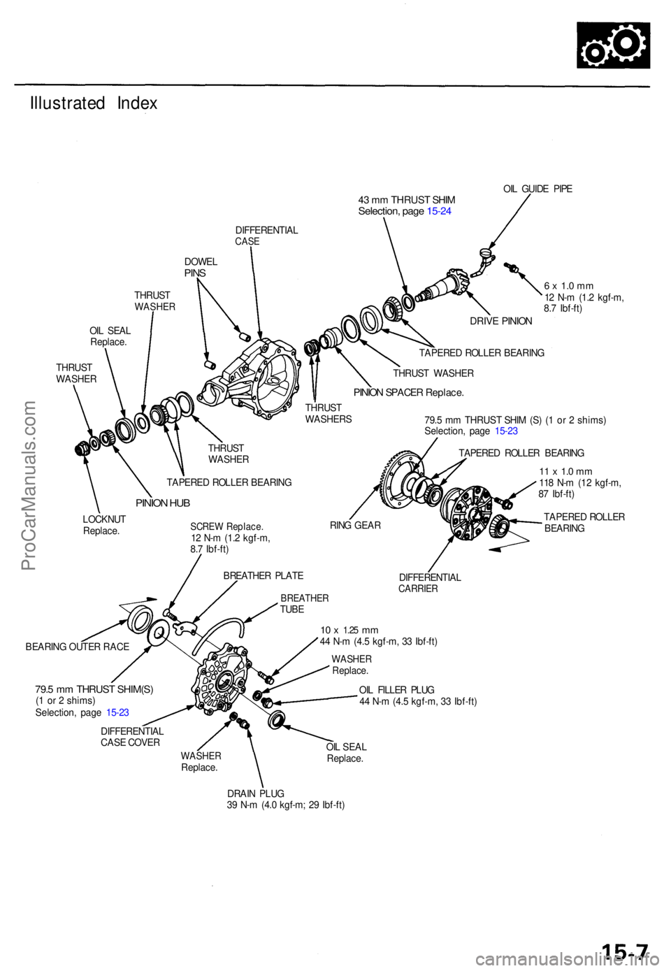
Illustrated Inde x
43 m m THRUS T SHI MSelection , pag e 15-2 4
OIL GUID E PIP E
DIFFERENTIA L
CASE
DOWE LPINS
THRUS TWASHE R
OIL SEA L
Replace .
THRUS T
WASHE RDRIVE PINIO N
TAPERE D ROLLE R BEARIN G
THRUS T WASHE R
PINION SPACE R Replace .
THRUST
WASHER S
LOCKNU T
Replace . TAPERE
D ROLLE R BEARIN G
PINION HU B
SCRE W Replace .12 N- m (1. 2 kgf-m ,
8. 7 Ibf-ft )
BREATHE R PLAT E RIN
G GEA R 79.
5 m m THRUS T SHI M (S ) ( 1 o r 2 shims )
Selection , pag e 15-2 3
TAPERE D ROLLE R BEARIN G
11 x 1. 0 m m118 N- m (1 2 kgf-m ,
8 7 Ibf-ft )
TAPERE D ROLLE R
BEARIN G
BREATHE RTUBE
BEARIN G OUTE R RAC E DIFFERENTIA
L
CARRIER
10 x 1.2 5 mm44 N- m (4. 5 kgf-m , 3 3 Ibf-ft )
WASHE RReplace .
79.5 m m THRUS T SHIM(S )(1 o r 2 shims )
Selection , pag e 15-2 3
DIFFERENTIA L
CAS E COVE R OI
L FILLE R PLU G
4 4 N- m (4. 5 kgf-m , 3 3 Ibf-ft )
WASHE RReplace. OI
L SEA L
Replace .
DRAI N PLU G
3 9 N- m (4. 0 kgf-m ; 2 9 Ibf-ft )
6 x 1. 0 m m12 N- m (1. 2 kgf-m ,
8. 7 Ibf-ft )
THRUS T
WASHE R
ProCarManuals.com
Page 438 of 1771
Differential Assembl y
Inspection
To establis h a startin g poin t befor e disassembly , inspec t
the following :
• Rin g gea r backlas h
• Tota l bearin g preloa d
• Gea r toot h contac t
NOTE:
• B e sur e th e differentia l i s a t roo m temperatur e befor e
inspecting .
• Recor d th e result s o f th e preliminar y inspections .
This informatio n wil l b e helpfu l during reassembly .
Ring gea r backlas h
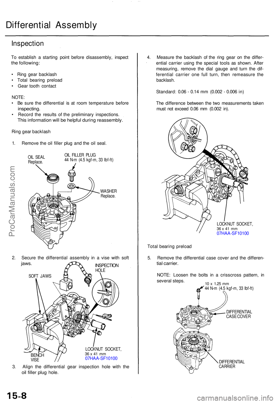
1 . Remov e th e oi l fille r plu g an d th e oi l seal .
OIL SEA L
Replace . OI
L FILLE R PLU G
4 4 N- m (4. 5 kgf-m , 3 3 Ibf-ft )
WASHE R
Replace .
BENCHVISE LOCKNU
T SOCKET ,
36 x 4 1 m m07HAA-SF1010 0
3. Alig n th e differentia l gea r inspectio n hol e wit h th e
oil fille r plu g hole .
4. Measur e th e backlas h o f th e rin g gea r o n th e differ -
entia l carrie r usin g th e specia l tool s a s shown . Afte r
measuring , remov e th e dia l gaug e an d tur n th e dif -
ferentia l carrie r on e ful l turn , the n remeasur e th e
backlash .
Standard : 0.0 6 - 0.1 4 m m (0.00 2 - 0.00 6 in )
Th e differenc e betwee n th e tw o measurement s take n
mus t no t excee d 0.0 6 m m (0.00 2 in) .
LOCKNU T SOCKET ,36 x 4 1 m m07HAA-SF1010 0
Total bearin g preloa d
5 . Remov e th e differentia l cas e cove r an d th e differen -
tial carrier .
NOTE: Loose n th e bolt s i n a crisscros s pattern , i n
severa l steps .
10 x 1.2 5 mm44 N- m (4. 5 kgf-m , 3 3 Ibf-ft )
DIFFERENTIA L
CAS E COVE R
DIFFERENTIA L
CARRIER
SOFT JAW S
INSPECTIO NHOLE
2. Secur e th e differentia l assembl y i n a vis e wit h sof t
jaws .
ProCarManuals.com
Page 439 of 1771
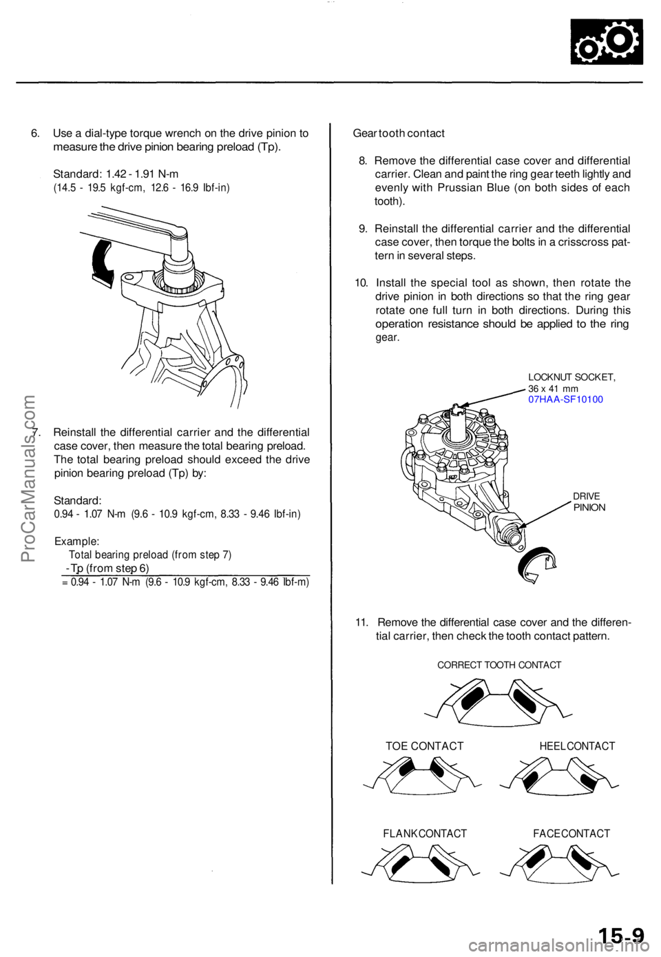
6. Us e a dial-typ e torqu e wrenc h o n th e driv e pinio n t o
measur e th e driv e pinio n bearin g preloa d (Tp) .
Standard : 1.4 2 - 1.9 1 N- m
(14. 5 - 19. 5 kgf-cm , 12. 6 - 16. 9 Ibf-in )
7. Reinstal l th e differentia l carrie r an d th e differentia l
cas e cover , the n measur e th e tota l bearin g preload .
Th e tota l bearin g preloa d shoul d excee d th e driv e
pinio n bearin g preloa d (Tp ) by :
Standard :
0.94 - 1.0 7 N- m (9. 6 - 10. 9 kgf-cm , 8.3 3 - 9.4 6 Ibf-in )
Example :
Total bearin g preloa d (fro m ste p 7 )
- T p (fro m ste p 6 )
= 0.9 4 - 1.0 7 N- m (9. 6 - 10. 9 kgf-cm , 8.3 3 - 9.4 6 Ibf-m )
Gear toot h contac t
8 . Remov e th e differentia l cas e cove r an d differentia l
carrier . Clea n an d pain t th e rin g gea r teet h lightl y an d
evenl y wit h Prussia n Blu e (o n bot h side s o f eac h
tooth) .
9 . Reinstal l th e differentia l carrie r an d th e differentia l
cas e cover , the n torqu e th e bolt s in a crisscros s pat -
ter n in severa l steps .
10 . Instal l th e specia l too l a s shown , the n rotat e th e
driv e pinio n i n bot h direction s s o tha t th e rin g gea r
rotat e on e ful l tur n i n bot h directions . Durin g thi s
operatio n resistanc e shoul d b e applie d t o th e rin g
gear .
LOCKNU T SOCKET ,36 x 41 m m07HAA-SF1010 0
DRIVEPINIO N
11. Remov e th e differentia l cas e cove r an d th e differen -
tia l carrier , the n chec k th e toot h contac t pattern .
CORREC T TOOT H CONTAC T
TOE CONTACT HEEL CONTAC T
FLANK CONTAC T FACE CONTAC T
ProCarManuals.com
Page 441 of 1771
5. Remove the differential carrier from the differential
case.
DIFFERENTIAL CARRIER
DIFFERENTIAL CASE
6. Remove the oil guide pipe.
OIL GUIDE
PIPE
7. Hold the drive pinion with a 1 1/4" (32 mm) hex bit
and socket as shown.
DRIVE PINION
1 1/4" (32 mm) HEX BIT and SOCKET
(Commercially available)
8. Raise the locknut tab from the groove of the drive
pinion, and remove the locknut, thrust washer and
pinion hub.
NOTE: Be sure the tab of the locknut is completely
clear of the groove or damage to the threads can
occur.
TAB
LOCKNUT
Replace.
THRUST WASHER
PINION HUBProCarManuals.com
Page 447 of 1771
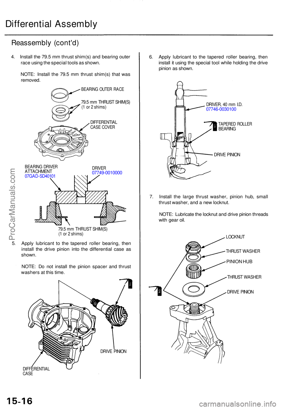
Differential Assembl y
Reassembl y (cont'd )
DIFFERENTIA LCASE COVE R
BEARIN G DRIVE RATTACHMEN T07GAD-SD4010 1
DRIVER07749-001000 0
79.5 m m THRUS T SHIM(S )(1 o r 2 shims )
5. Appl y lubrican t t o th e tapere d rolle r bearing , the n
instal l th e driv e pinio n int o th e differentia l cas e a s
shown .
NOTE : D o no t instal l th e pinio n space r an d thrus t
washer s a t thi s time .
DIFFERENTIA LCASE
DRIV E PINIO N
6. Appl y lubrican t t o th e tapere d rolle r bearing , the n
instal l i t usin g th e specia l too l whil e holdin g th e driv e
pinio n a s shown .
DRIVER , 4 0 m m I.D .07746-003010 0
TAPERED ROLLE RBEARIN G
DRIVE PINIO N
7. Instal l th e larg e thrus t washer , pinio n hub , smal l
thrus t washer , an d a ne w locknut .
NOTE : Lubricat e th e locknu t an d driv e pinio n thread s
wit h gea r oil .
LOCKNU T
THRUST WASHE R
PINION HUB
THRUST WASHE R
DRIVE PINIO N
4. Instal l th e 79. 5 m m thrus t shim(s ) an d bearin g oute r
rac e usin g th e specia l tool s a s shown .
NOTE : Instal l th e 79. 5 m m thrus t shim(s ) tha t wa s
removed .
IBEARING OUTE R RAC E
79.5 m m THRUS T SHIM(S )(1 o r 2 shims )
ProCarManuals.com