1995 ACURA TL lock
[x] Cancel search: lockPage 184 of 1771
Troubleshooting
Troubleshootin g Procedure s (cont'd )
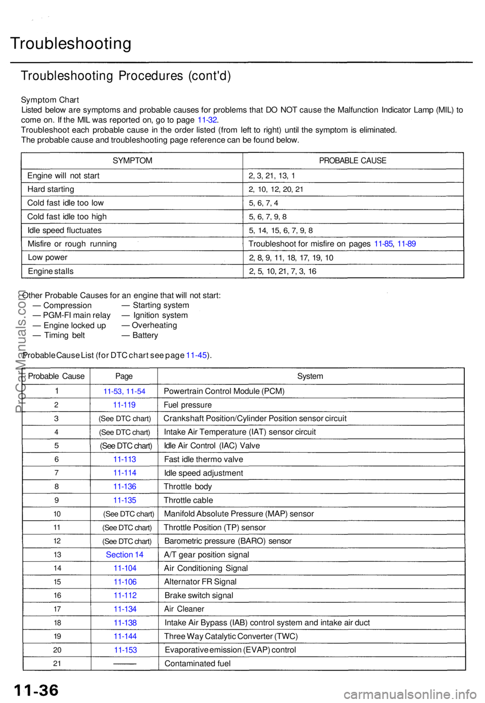
Sympto m Char t
Liste d belo w ar e symptom s an d probabl e cause s fo r problem s tha t D O NO T caus e th e Malfunctio n Indicato r Lam p (MIL ) t o
com e on . I f th e MI L wa s reporte d on , g o to pag e 11-32 .
Troubleshoo t eac h probabl e caus e in th e orde r liste d (fro m lef t t o right ) unti l th e sympto m is eliminated .
Th e probabl e caus e an d troubleshootin g pag e referenc e ca n b e foun d below .
SYMPTO M
Engin e wil l no t star t
Har d startin g
Col d fas t idl e to o lo w
Col d fas t idl e to o hig h
Idl e spee d fluctuate s
Misfir e o r roug h runnin g
Lo w powe r
Engin e stall s
PROBABL E CAUS E
2, 3 , 21 , 13 , 1
2 , 10 , 12 , 20 , 2 1
5, 6 , 7 , 4
5 , 6 , 7 , 9 , 8
5 , 14 , 15 , 6 , 7 , 9 , 8
Troubleshoo t fo r misfir e o n page s 11-85 , 11-8 9
2, 8 , 9 , 11 , 18 , 17 , 19 , 1 0
2, 5 , 10 , 21 , 7 , 3 , 1 6
Othe r Probabl e Cause s fo r a n engin e tha t wil l no t start :
— Compressio n
— PGM-F I mai n rela y
— Engin e locke d u p
— Timin g bel t
Probabl e Caus e Lis t (for DTC chart see page 11-45).
—
Startin g syste m
— Ignitio n syste m
— Overheatin g
— Batter y
Probabl e Caus e
1
2
3
4
5
6
7
8
9
10
1 1
1 2
13
1 4
15
1 6
17
18
19
2 0
2 1
Pag e
11-5 3, 11-54
11-11 9
(See DTC chart)
(See DTC chart)
(See DTC chart)
11-113
11-11 4
11-136
11-13 5
(See DTC chart)
(See DTC chart)
(See DTC chart)
Sectio n 1 4
11-10 4
11-106
11-112
11-13 4
11-138
11-14 4
11-153
System
Powertrai n Contro l Modul e (PCM )
Fuel pressur e
Crankshaf t Position/Cylinde r Positio n senso r circui t
Intak e Ai r Temperatur e (IAT ) senso r circui t
Idl e Ai r Contro l (IAC ) Valv e
Fas t idl e therm o valv e
Idl e spee d adjustmen t
Throttl e bod y
Throttl e cabl e
Manifol d Absolut e Pressur e (MAP ) senso r
Throttl e Positio n (TP ) senso r
Barometri c pressur e (BARO ) senso r
A/ T gea r positio n signa l
Ai r Conditionin g Signa l
Alternato r F R Signa l
Brak e switc h signa l
Air Cleane r
Intake Ai r Bypas s (IAB ) contro l syste m an d intak e ai r duc t
Thre e Wa y Catalyti c Converte r (TWC )
Evaporativ e emissio n (EVAP ) contro l
Contaminate d fue l
ProCarManuals.com
Page 213 of 1771
Idle Contro l Syste m
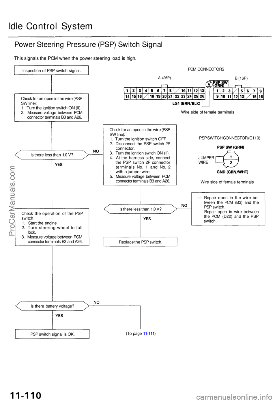
Power Steerin g Pressur e (PSP ) Switc h Signa l
This signal s th e PC M whe n th e powe r steerin g loa d is high .
Inspectio n o f PS P switc h signal .
Chec k fo r a n ope n in th e wir e (PS P
S W line) :
1. Tur n th e ignitio n switc h O N (II) .2. Measur e voltag e betwee n PC M
connecto r terminal s B 3 an d A26 .
I s ther e les s tha n 1. 0 V ?
Chec k th e operatio n o f th e PS P
switch :
1 . Star t th e engin e
2. Tur n steerin g whee l t o ful llock .3. Measur e voltag e betwee n PC Mconnecto r terminal s B 3 an d A26 .
I s ther e batter y voltage ?
PCM CONNECTOR S
A (26P)B (16P)
Check fo r a n ope n in th e wir e (PS P
S W line) :
1. Tur n th e ignitio n switc h OFF .2. Disconnec t th e PS P switc h 2 P
connector .
3 . Tur n th e ignitio n switc h O N (II) .
4 . A t th e harnes s side , connec t
th e PS P switc h 2 P connecto r
terminal s No . 1 an d No . 2
wit h a jumpe r wire .5. Measur e voltag e betwee n PC M
connecto r terminal s B 3 an d A26 . Wir
e sid e o f femal e terminal s
I s ther e les s tha n 1. 0 V ? —
Repai r ope n i n th e wire be-
twee n th e PC M (B3 ) an d th e
PS P switch .
— Repai r ope n i n wir e betwee n
the PC M (D22 ) and th e PS Pswitch .
(T o pag e 11-111 )
PS P switc h signa l i s OK . Replac
e th e PS P switch . Wir
e sid e o f femal e terminal s
JUMPERWIRE
PSP SWITC H CONNECTO R (C110 )
ProCarManuals.com
Page 241 of 1771
Throttle Cable
Inspection/Adjustment
1. Start the engine. Hold the engine at 3,000 rpm with
no load (transmission in or position) until the
radiator fan comes on, then let it idle.
2. Check that the throttle cable operates smoothly with
no binding or sticking. Repair as necessary.
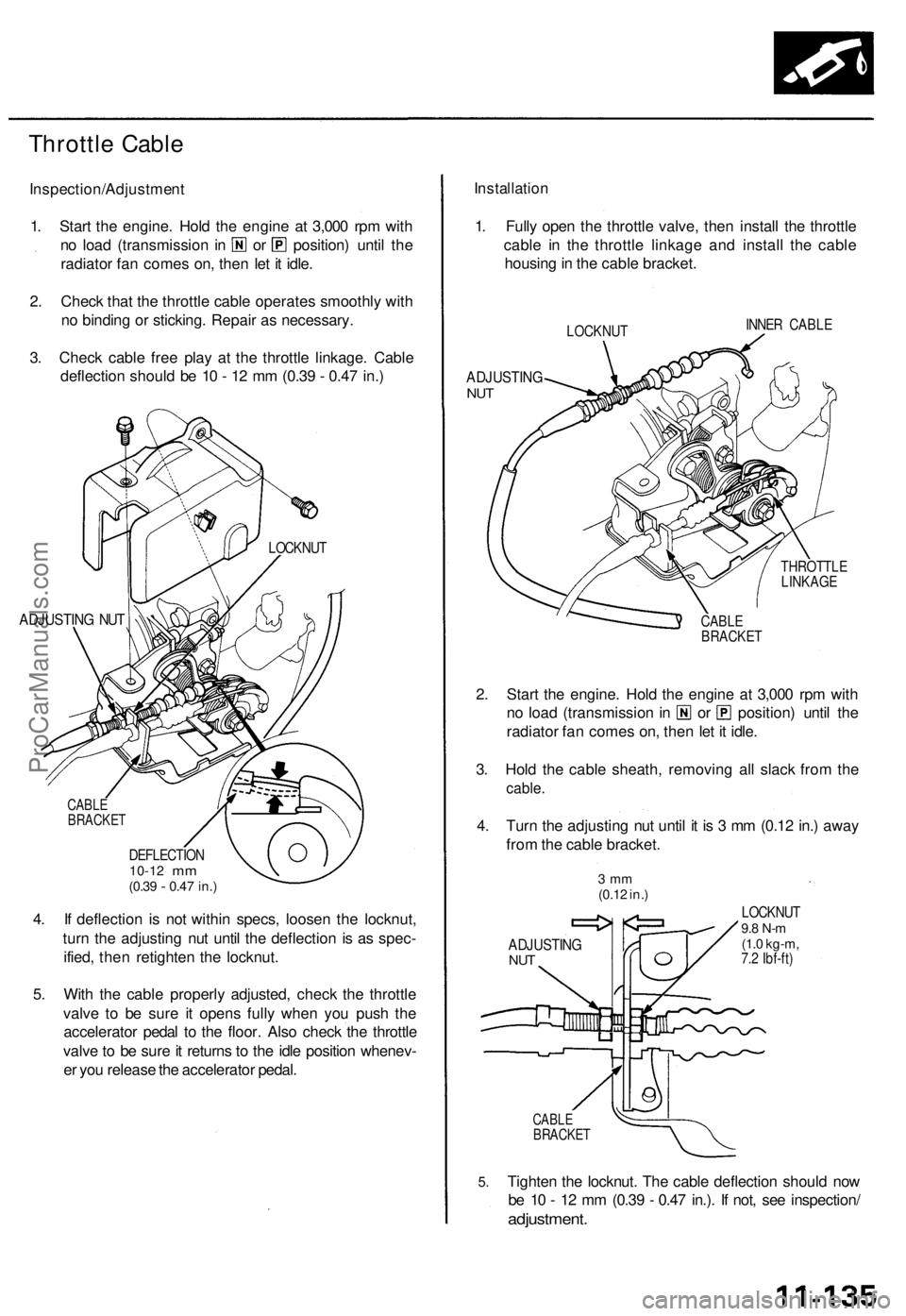
3. Check cable free play at the throttle linkage. Cable
deflection should be 10 - 12 mm (0.39 - 0.47 in.)
ADJUSTING NUT
CABLE
BRACKET
DEFLECTION
10-12
mm
(0.39
-
0.47 in.)
4. If deflection is not within specs, loosen the locknut,
turn the adjusting nut until the deflection is as spec-
ified, then retighten the locknut.
5. With the cable properly adjusted, check the throttle
valve to be sure it opens fully when you push the
accelerator pedal to the floor. Also check the throttle
valve to be sure it returns to the idle position whenev-
er you release the accelerator pedal.
Installation
1. Fully open the throttle valve, then install the throttle
cable in the throttle linkage and install the cable
housing in the cable bracket.
LOCKNUT
INNER CABLE
ADJUSTING
NUT
THROTTLE
LINKAGE
CABLE
BRACKET
2. Start the engine. Hold the engine at 3,000 rpm with
no load (transmission in or position) until the
radiator fan comes on, then let it idle.
3. Hold the cable sheath, removing all slack from the
cable.
4. Turn the adjusting nut until it is 3 mm (0.12 in.) away
from the cable bracket.
3 mm
(0.12 in.)
ADJUSTING
NUT
LOCKNUT
9.8 N-m
(1.0 kg-m,
7.2 Ibf-ft)
5.
CABLE
BRACKET
Tighten the locknut. The cable deflection should now
be 10 - 12 mm (0.39 - 0.47 in.). If not, see inspection/
adjustment.
LOCKNUTProCarManuals.com
Page 245 of 1771
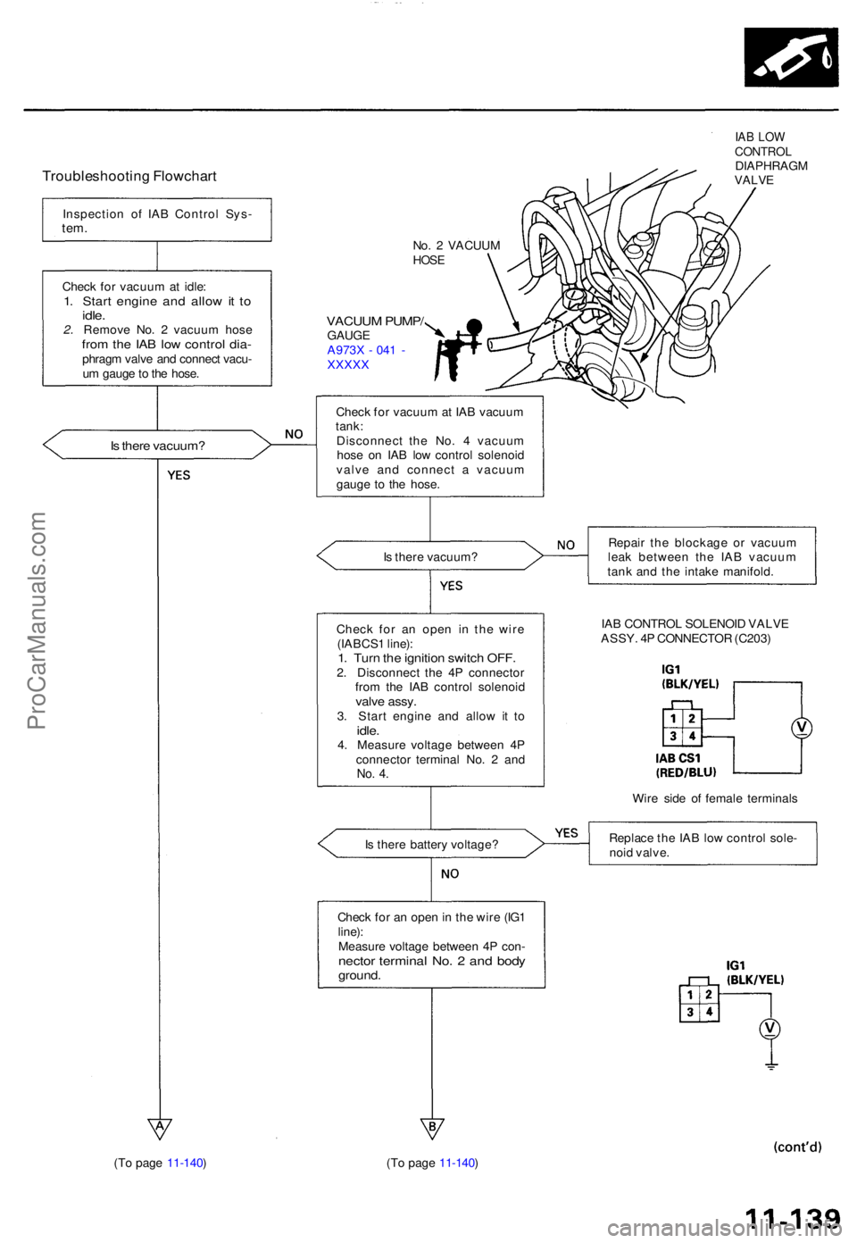
Troubleshooting Flowchar t
Inspectio n o f IA B Contro l Sys -tem.
No. 2 VACUU MHOSE
Chec k fo r vacuu m at idle :1. Star t engin e an d allo w it t oidle .2. Remov e No . 2 vacuu m hos efrom th e IA B lo w contro l dia -phrag m valv e an d connec t vacu -
u m gaug e to th e hose .
VACUU M PUMP /GAUG EA973X - 04 1 -XXXX X
Is ther e vacuum ?
Check fo r vacuu m at IA B vacuu m
tank :
Disconnec t th e No . 4 vacuu m
hos e o n IA B lo w contro l solenoi d
valv e an d connec t a vacuu m
gaug e t o th e hose .
IAB LO WCONTRO LDIAPHRAG MVALVE
Is ther e vacuum ? Repai
r th e blockag e o r vacuu m
lea k betwee n th e IA B vacuu m
tan k an d th e intak e manifold .
Chec k fo r a n ope n i n th e wir e
(IABCS 1 line) :
1. Tur n th e ignitio n switc h OFF .2. Disconnec t th e 4 P connecto r
fro m th e IA B contro l solenoi d
valve assy .3. Star t engin e an d allo w i t t oidle .4. Measur e voltag e betwee n 4 P
connecto r termina l No . 2 an d
No. 4 .
IA B CONTRO L SOLENOI D VALV E
ASSY . 4 P CONNECTO R (C203 )
Wir e sid e o f femal e terminal s
I s ther e batter y voltage ? Replac
e th e IA B lo w contro l sole -
noi d valve .
Chec k fo r a n ope n in th e wir e (IG 1
line) :
Measur e voltag e betwee n 4 P con -
necto r termina l No . 2 an d bod yground .
(To pag e 11-140 ) (To pag e 11-140 )
ProCarManuals.com
Page 246 of 1771
Intake Ai r Syste m
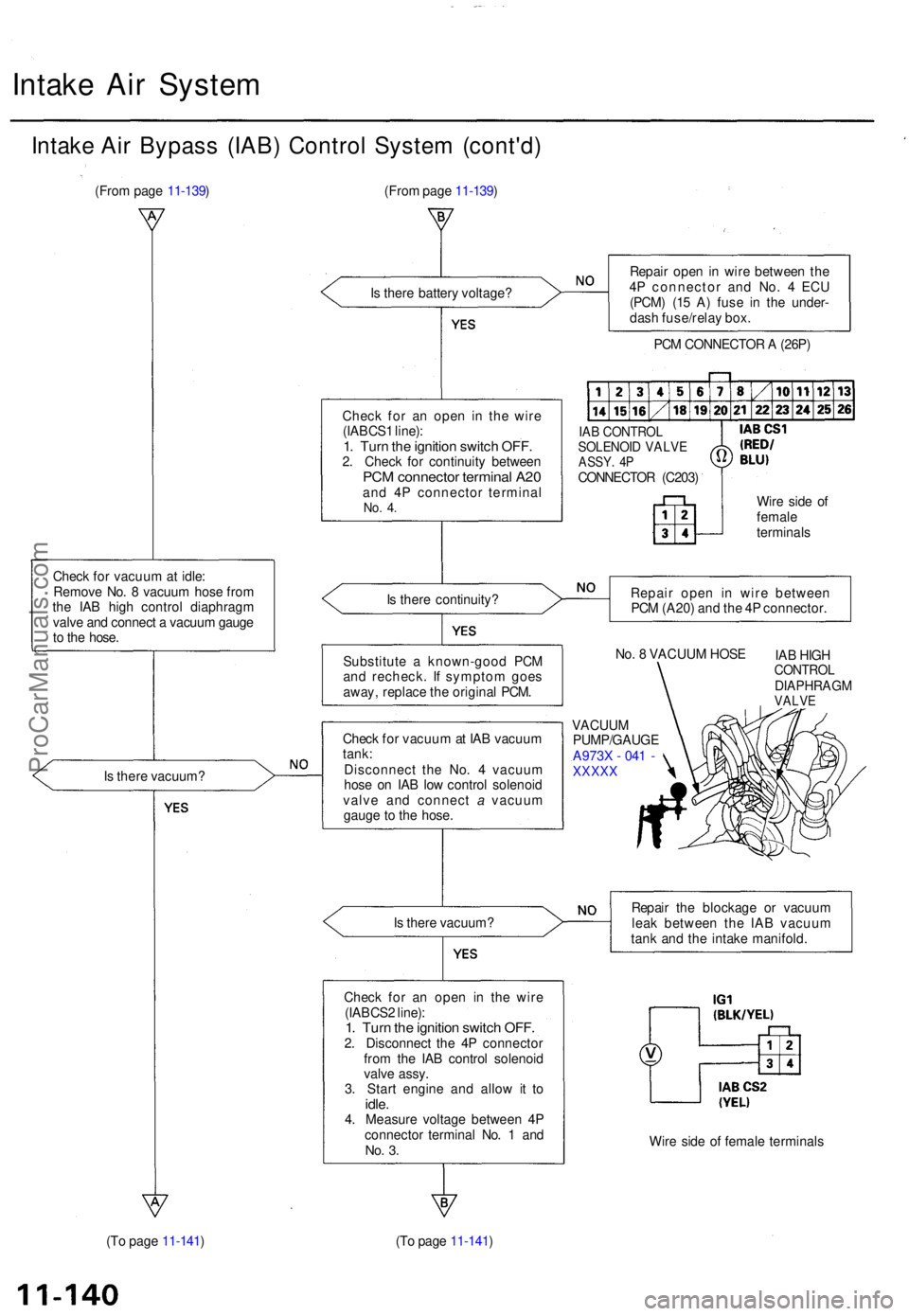
Intake Ai r Bypas s (IAB ) Contro l Syste m (cont'd )
(From pag e 11-139 )
Chec k fo r vacuu m at idle :
Remov e No . 8 vacuu m hos e fro m
th e IA B hig h contro l diaphrag m
valv e an d connec t a vacuu m gaug e
t o th e hose .
I s ther e vacuum ?
(T o pag e 11-141 ) (Fro
m pag e 11-139 )
I s ther e batter y voltage ?
Chec k fo r a n ope n i n th e wir e
(IABCS 1 line) :
1. Tur n th e ignitio n switc h OFF .2. Chec k fo r continuit y betwee nPCM connecto r termina l A2 0and 4 P connecto r termina lNo. 4 .
Is ther e continuity ?
Substitut e a known-goo d PC M
an d recheck . I f sympto m goe s
away , replac e th e origina l PCM .
Chec k fo r vacuu m at IA B vacuu m
tank :
Disconnec t th e No . 4 vacuu m
hos e o n IA B lo w contro l solenoi d
valv e an d connec t a vacuu m
gaug e t o th e hose .
I s ther e vacuum ?
Chec k fo r a n ope n i n th e wir e
(IABCS 2 line) :
1. Tur n th e ignitio n switc h OFF .2. Disconnec t th e 4 P connecto r
fro m th e IA B contro l solenoi d
valv e assy .
3 . Star t engin e an d allo w i t t o
idle .4. Measur e voltag e betwee n 4 P
connecto r termina l No . 1 an d
No. 3 .
(T o pag e 11-141 ) Repai
r ope n in wir e betwee n th e
4 P connecto r an d No . 4 EC U
(PCM ) (1 5 A ) fus e i n th e under -
das h fuse/rela y box .
PC M CONNECTO R A (26P )
IAB CONTRO LSOLENOID VALV EASSY. 4 PCONNECTO R (C203 )
Wire sid e o f
femal e
terminal s
Repai r ope n i n wir e betwee n
PC M (A20 ) an d th e 4 P connector .
No . 8 VACUU M HOS E
IAB HIG H
CONTRO LDIAPHRAG MVALVE
VACUU M
PUMP/GAUG E
A973 X - 04 1 -
XXXX X
Repair th e blockag e o r vacuu m
lea k betwee n th e IA B vacuu m
tan k an d th e intak e manifold .
Wir e sid e o f femal e terminal s
ProCarManuals.com
Page 257 of 1771
Description
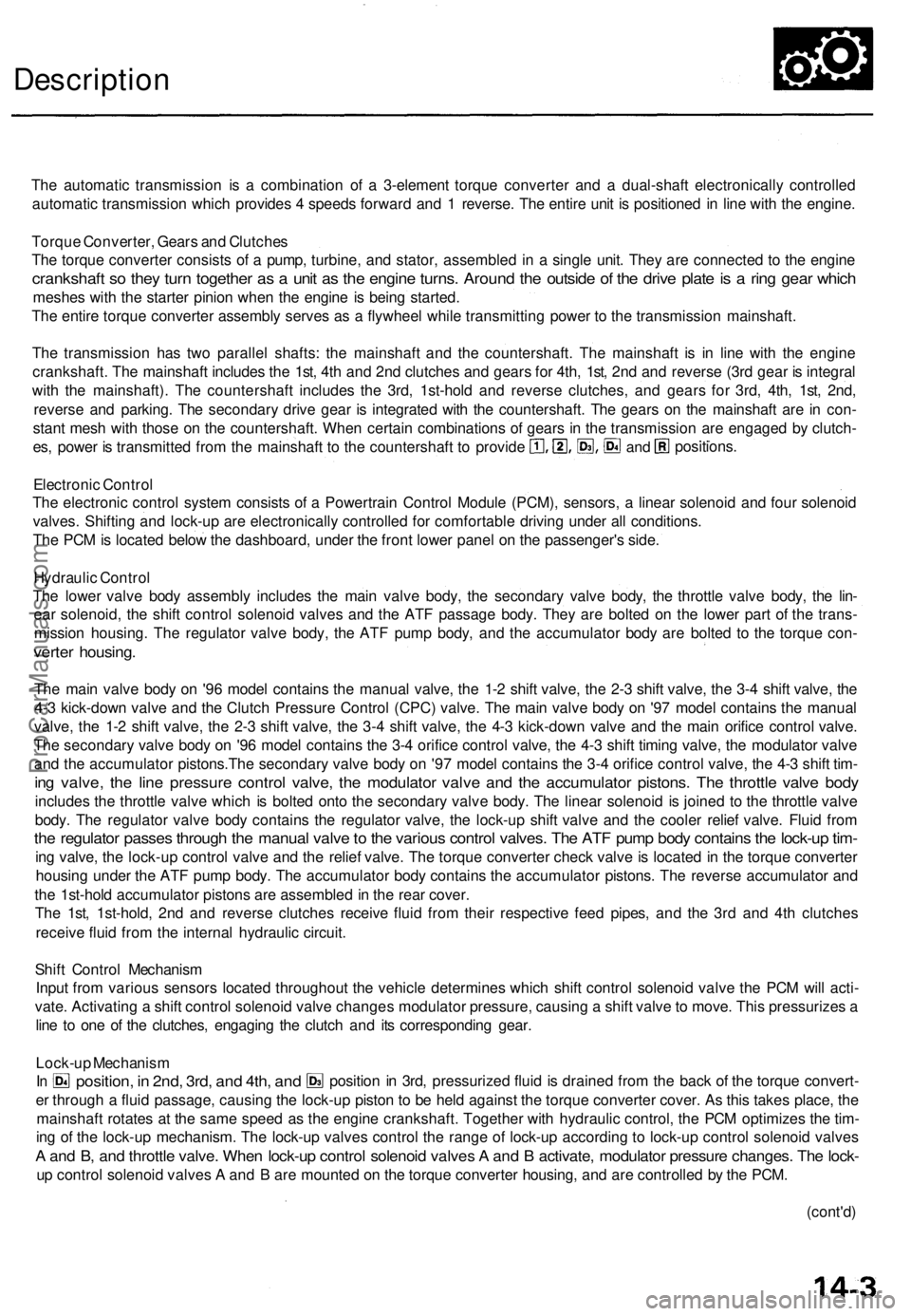
The automatic transmission is a combination of a 3-element torque converter and a dual-shaft electronically controlled
automatic transmission which provides 4 speeds forward and 1 reverse. The entire unit is positioned in line with the engine.
Torque Converter, Gears and Clutches
The torque converter consists of a pump, turbine, and stator, assembled in a single unit. They are connected to the engine
crankshaft so they turn together as a unit as the engine turns. Around the outside of the drive plate is a ring gear which
meshes with the starter pinion when the engine is being started.
The entire torque converter assembly serves as a flywheel while transmitting power to the transmission mainshaft.
The transmission has two parallel shafts: the mainshaft and the countershaft. The mainshaft is in line with the engine
crankshaft. The mainshaft includes the 1st, 4th and 2nd clutches and gears for 4th, 1st, 2nd and reverse (3rd gear is integral
with the mainshaft). The countershaft includes the 3rd, 1st-hold and reverse clutches, and gears for 3rd, 4th, 1st, 2nd,
reverse and parking. The secondary drive gear is integrated with the countershaft. The gears on the mainshaft are in con-
stant mesh with those on the countershaft. When certain combinations of gears in the transmission are engaged by clutch-
positions.
and
es, power is transmitted from the mainshaft to the countershaft to provide
Electronic Control
The electronic control system consists of a Powertrain Control Module (PCM), sensors, a linear solenoid and four solenoid
valves. Shifting and lock-up are electronically controlled for comfortable driving under all conditions.
The PCM is located below the dashboard, under the front lower panel on the passenger's side.
Hydraulic Control
The lower valve body assembly includes the main valve body, the secondary valve body, the throttle valve body, the lin-
ear solenoid, the shift control solenoid valves and the ATF passage body. They are bolted on the lower part of the trans-
mission housing. The regulator valve body, the ATF pump body, and the accumulator body are bolted to the torque con-
verter housing.
The main valve body on '96 model contains the manual valve, the 1-2 shift valve, the 2-3 shift valve, the 3-4 shift valve, the
4-3 kick-down valve and the Clutch Pressure Control (CPC) valve. The main valve body on '97 model contains the manual
valve, the 1-2 shift valve, the 2-3 shift valve, the 3-4 shift valve, the 4-3 kick-down valve and the main orifice control valve.
The secondary valve body on '96 model contains the 3-4 orifice control valve, the 4-3 shift timing valve, the modulator valve
and the accumulator pistons.The secondary valve body on '97 model contains the 3-4 orifice control valve, the 4-3 shift tim-
ing valve, the line pressure control valve, the modulator valve and the accumulator pistons. The throttle valve body
includes the throttle valve which is bolted onto the secondary valve body. The linear solenoid is joined to the throttle valve
body. The regulator valve body contains the regulator valve, the lock-up shift valve and the cooler relief valve. Fluid from
the regulator passes through the manual valve to the various control valves. The ATF pump body contains the lock-up tim-
ing valve, the lock-up control valve and the relief valve. The torque converter check valve is located in the torque converter
housing under the ATF pump body. The accumulator body contains the accumulator pistons. The reverse accumulator and
the 1st-hold accumulator pistons are assembled in the rear cover.
The 1st, 1st-hold, 2nd and reverse clutches receive fluid from their respective feed pipes, and the 3rd and 4th clutches
receive fluid from the internal hydraulic circuit.
Shift Control Mechanism
Input from various sensors located throughout the vehicle determines which shift control solenoid valve the PCM will acti-
vate. Activating a shift control solenoid valve changes modulator pressure, causing a shift valve to move. This pressurizes a
line to one of the clutches, engaging the clutch and its corresponding gear.
er through a fluid passage, causing the lock-up piston to be held against the torque converter cover. As this takes place, the
mainshaft rotates at the same speed as the engine crankshaft. Together with hydraulic control, the PCM optimizes the tim-
ing of the lock-up mechanism. The lock-up valves control the range of lock-up according to lock-up control solenoid valves
A and B, and throttle valve. When lock-up control solenoid valves A and B activate, modulator pressure changes. The lock-
up control solenoid valves A and B are mounted on the torque converter housing, and are controlled by the PCM.
(cont'd)
Lock-up Mechanism
In
position, in 2nd, 3rd, and 4th, and
position in 3rd, pressurized fluid is drained from the back of the torque convert-ProCarManuals.com
Page 258 of 1771
Description
(cont'd)
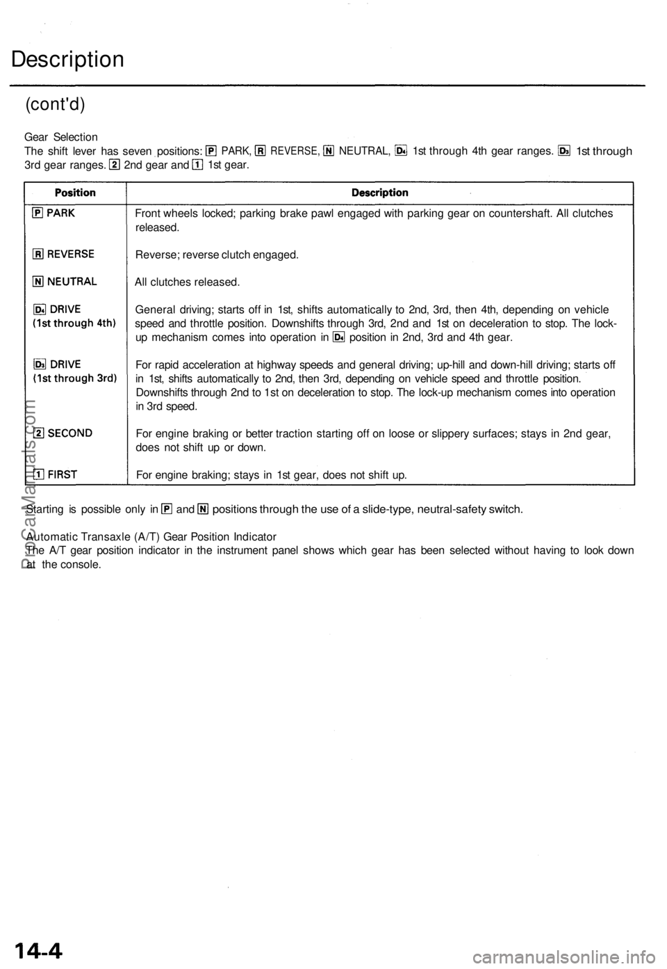
Front wheel s locked ; parkin g brak e paw l engage d wit h parkin g gea r o n countershaft . Al l clutche s
released .
Reverse ; revers e clutc h engaged .
Al l clutche s released .
Automati c Transaxl e (A/T ) Gea r Positio n Indicato r
Th e A/ T gea r positio n indicato r i n th e instrumen t pane l show s whic h gea r ha s bee n selecte d withou t havin g t o loo k dow n
a t the c onsole .
position s throug h th e us e o f a slide-type , neutral-safet y switch .Starting i s possibl e onl y i nan d
Gea r Selectio n
Th e shif t leve r ha s seve n positions :
3r d gea r ranges . 1s
t gear .
2n d gea r an d
PARK ,REVERSE ,NEUTRAL,1st throug h 4t h gea r ranges .1st throug h
For rapi d acceleratio n a t highwa y speed s an d genera l driving ; up-hil l an d down-hil l driving ; start s of f
i n 1st , shift s automaticall y t o 2nd , the n 3rd , dependin g o n vehicl e spee d an d throttl e position .
Downshift s throug h 2n d to
1st o n deceleratio n t o stop . Th e lock-u p mechanis m come s int o operatio n
i n 3r d speed .
Fo r engin e brakin g o r bette r tractio n startin g of f o n loos e o r slipper y surfaces ; stay s i n 2n d gear ,
doe s no t shif t u p o r down .
Fo r engin e braking ; stay s i n 1s t gear , doe s no t shif t up .
Genera
l driving ; start s of f i n 1st , shift s automaticall y t o 2nd , 3rd , the n 4th , dependin g o n vehicl e
spee d an d throttl e position . Downshift s throug h 3rd , 2n d an d 1s t o n deceleratio n t o stop . Th e lock -
u p mechanis m come s int o operatio n i n positio n in 2nd , 3r d an d 4t h gear .
ProCarManuals.com
Page 260 of 1771
Description
Clutches
The four-speed automatic transmission uses hydraulically-actuated clutches to engage or disengage the transmission gears.
When the hydraulic pressure is introduced into the clutch drum, the clutch piston moves. This presses the friction discs
and steel plates together, locking them so they don't slip. Power is then transmitted through the engaged clutch pack to its
hub-mounted gear.
Likewise, when the hydraulic pressure is bled from the clutch pack, the piston releases the friction discs and steel plates, and
they are free to slide past each. This allows the gear to spin independently of its shaft, transmitting no power.
1st Clutch
The 1st clutch, engages/disengages 1st gear, and is located at the middle of the mainshaft. The 1st clutch is joined back-to-
back to the 4th clutch. The 1st clutch is supplied hydraulic pressure by its ATF feed pipe within the mainshaft.
shaft. The 1st-hold clutch is supplied hydraulic pressure by its ATF feed pipe within the countershaft.
1st-hold Clutch
The 1st-hold clutch engages/disengages 1st-hold,
position or
position, and is located at the middle of the counter-
2nd Clutch
The 2nd clutch engages/disengages 2nd gear, and is located on the rear end of the mainshaft. The 2nd clutch is supplied
hydraulic pressure by its ATF feed pipe within the mainshaft.
3rd Clutch
The 3rd clutch engages/disengages 3rd gear, and is located at the end of the countershaft, opposite the rear cover. The
3rd clutch is supplied hydraulic pressure by a circuit connected to the internal hydraulic circuit.
4th Clutch
The 4th clutch engages/disengages 4th gear, and is located at the middle of the mainshaft. The 4th clutch is joined back-
to-back to the 1st clutch. The 4th clutch is supplied hydraulic pressure by a circuit connected to the internal hydraulic cir-
cuit.
Reverse Clutch
The reverse clutch engages/disengages reverse gear, and is located on the rear end of the countershaft. The reverse clutch is
supplied hydraulic pressure by its ATF feed pipe within the countershaft.
One-way Clutch
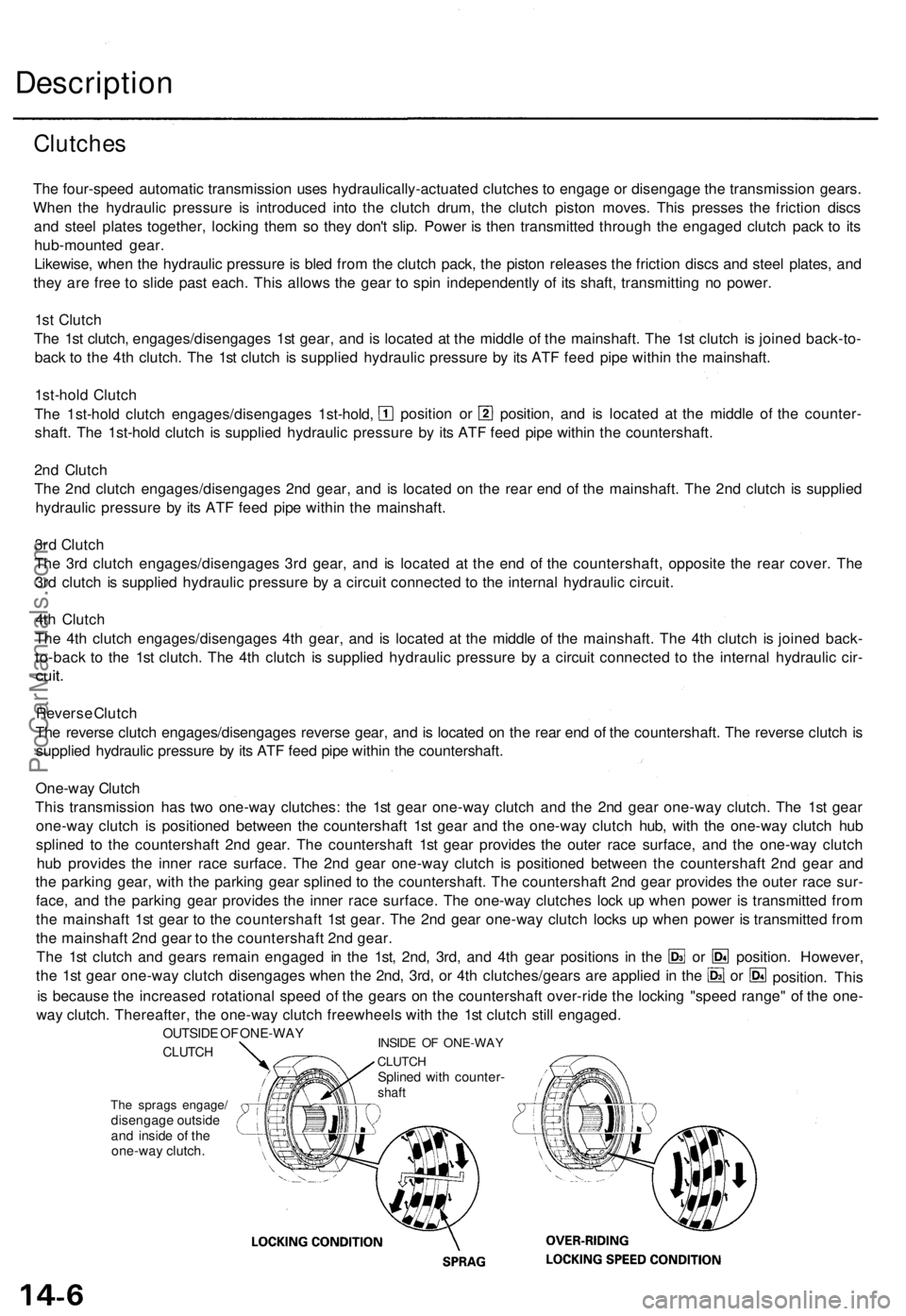
This transmission has two one-way clutches: the 1st gear one-way clutch and the 2nd gear one-way clutch. The 1st gear
one-way clutch is positioned between the countershaft 1st gear and the one-way clutch hub, with the one-way clutch hub
splined to the countershaft 2nd gear. The countershaft 1st gear provides the outer race surface, and the one-way clutch
hub provides the inner race surface. The 2nd gear one-way clutch is positioned between the countershaft 2nd gear and
the parking gear, with the parking gear splined to the countershaft. The countershaft 2nd gear provides the outer race sur-
face, and the parking gear provides the inner race surface. The one-way clutches lock up when power is transmitted from
the mainshaft 1st gear to the countershaft 1st gear. The 2nd gear one-way clutch locks up when power is transmitted from
the mainshaft 2nd gear to the countershaft 2nd gear.
The 1st clutch and gears remain engaged in the 1st, 2nd, 3rd, and 4th gear positions in the
the 1st gear one-way clutch disengages when the 2nd, 3rd, or 4th clutches/gears are applied in the
The sprags engage/
disengage outside
and inside of the
one-way clutch.
is because the increased rotational speed of the gears on the countershaft over-ride the locking "speed range" of the one-
way clutch. Thereafter, the one-way clutch freewheels with the 1st clutch still engaged.
INSIDE OF ONE-WAY
CLUTCH
Splined with counter-
shaft
OUTSIDE OF ONE-WAY
CLUTCH
position. However,
or
or
position. ThisProCarManuals.com