1995 ACURA TL lock
[x] Cancel search: lockPage 63 of 1771
Timing Bel t
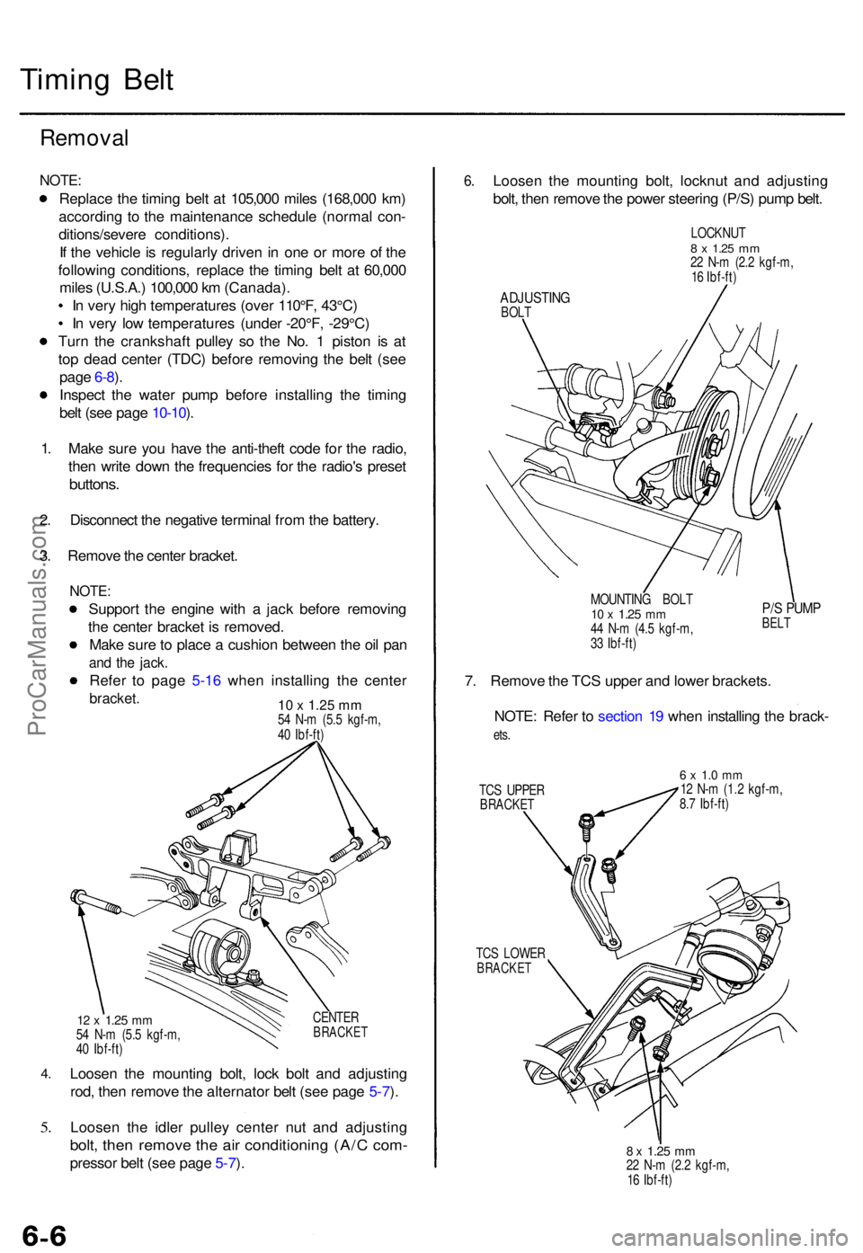
Remova l
NOTE:
Replac e th e timin g bel t a t 105,00 0 mile s (168,00 0 km )
accordin g t o th e maintenanc e schedul e (norma l con -
ditions/sever e conditions) .
I f th e vehicl e is regularl y drive n i n on e o r mor e o f th e
followin g conditions , replac e th e timin g bel t a t 60,00 0
mile s (U.S.A. ) 100,00 0 k m (Canada) .
I n ver y hig h temperature s (ove r 110°F , 43°C )
I n ver y lo w temperature s (unde r -20°F , -29°C )
Tur n th e crankshaf t pulle y s o th e No . 1 pisto n i s a t
to p dea d cente r (TDC ) befor e removin g th e bel t (se e
pag e 6-8 ).
Inspec t th e wate r pum p befor e installin g th e timin g
bel t (se e pag e 10-10 ).
1 . Mak e sur e yo u hav e th e anti-thef t cod e fo r th e radio ,
the n writ e dow n th e frequencie s fo r th e radio' s prese t
buttons .
2. Disconnec t th e negativ e termina l fro m th e battery .
3 . Remov e th e cente r bracket .
NOTE:
Suppor t th e engin e wit h a jac k befor e removin g
th e cente r bracke t i s removed .
Mak e sur e to plac e a cushio n betwee n th e oi l pa n
and th e jack .
Refer t o pag e 5-1 6 whe n installin g th e cente r
bracket. 10 x 1.25 mm54 N- m (5. 5 kgf-m ,
4 0 Ibf-ft )
4.
5.
CENTE RBRACKE T12 x 1.2 5 mm54 N- m (5. 5 kgf-m ,
4 0 Ibf-ft )
Loose n th e mountin g bolt , loc k bol t an d adjustin g
rod , the n remov e th e alternato r bel t (se e pag e 5-7 ).
Loose n th e idle r pulle y cente r nu t an d adjustin g
bolt, the n remov e th e ai r conditionin g (A/ C com -
presso r bel t (se e pag e 5-7 ).
6 .Loose n th e mountin g bolt , locknu t an d adjustin g
bolt , the n remov e th e powe r steerin g (P/S ) pum p belt .
LOCKNU T8 x 1.2 5 mm22 N- m (2. 2 kgf-m ,
1 6 Ibf-ft )
ADJUSTIN GBOLT
MOUNTING BOL T
10 x 1.2 5 mm44 N- m (4. 5 kgf-m ,
3 3 Ibf-ft )
P/S PUM PBELT
7. Remov e th e TC S uppe r an d lowe r brackets .
NOTE : Refe r t o sectio n 1 9 whe n installin g th e brack -
ets.
TC S UPPE RBRACKE T
6 x 1. 0 m m12 N- m (1. 2 kgf-m ,
8. 7 Ibf-ft )
TC S LOWE R
BRACKE T
8 x 1.2 5 mm22 N- m (2. 2 kgf-m ,
1 6 Ibf-ft )
ProCarManuals.com
Page 67 of 1771
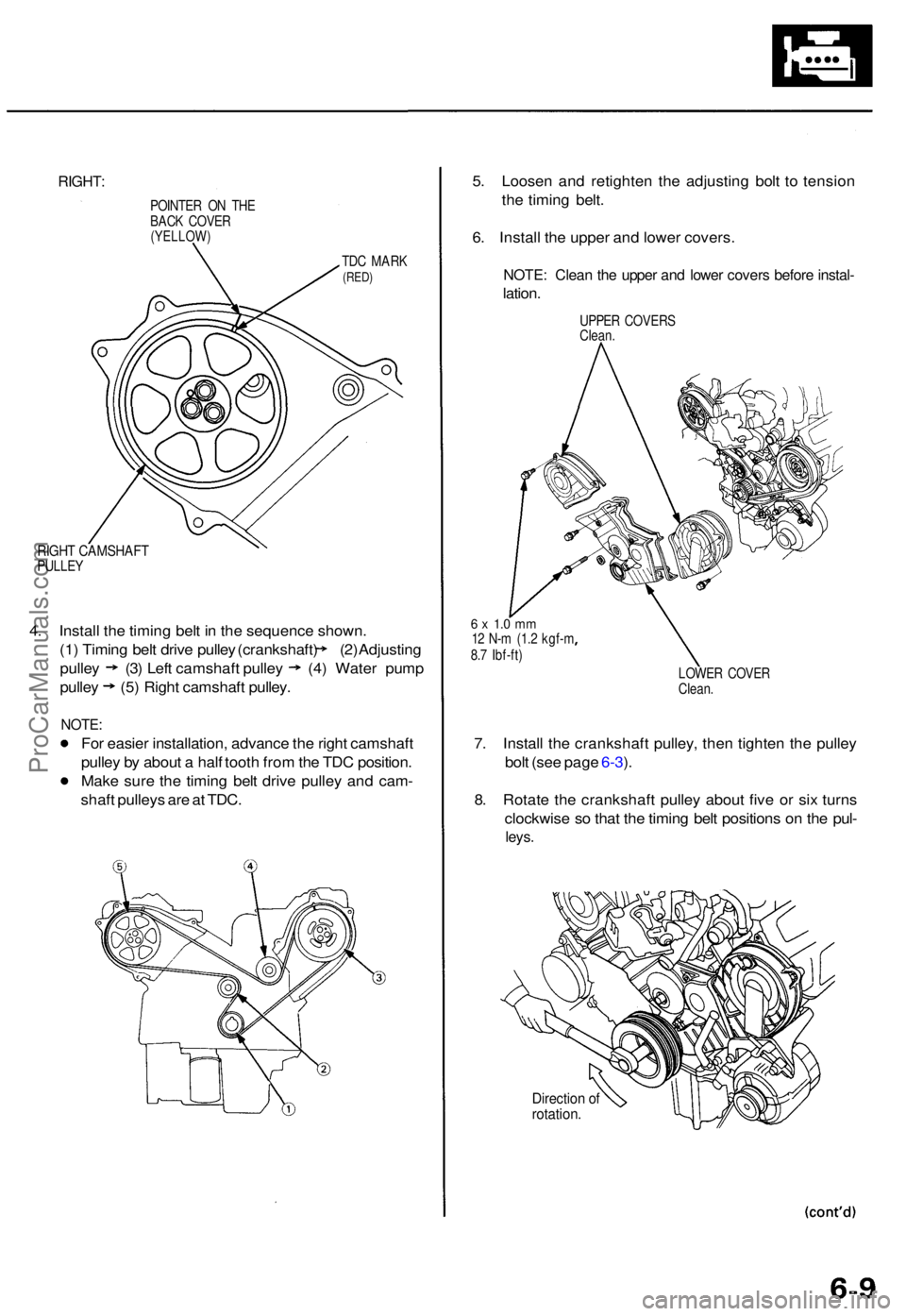
RIGHT:
POINTE R O N TH E
BAC K COVE R
(YELLOW )
TDC MAR K(RED)
RIGHT CAMSHAF TPULLEY
4. Instal l th e timin g bel t i n th e sequenc e shown .
(1) Timin g bel t driv e pulle y (crankshaft ) (2 ) Adjustin g
pulley (3 ) Lef t camshaf t pulle y (4) Wate r pum p
pulley (5) Right camshaf t pulley .
NOTE:
For easie r installation , advanc e th e righ t camshaf t
pulle y b y abou t a hal f toot h fro m th e TD C position .
Mak e sur e th e timin g bel t driv e pulle y an d cam -
shaf t pulley s ar e a t TDC . 5
. Loose n an d retighte n th e adjustin g bol t t o tensio n
th e timin g belt .
6 . Instal l th e uppe r an d lowe r covers .
NOTE: Clea n th e uppe r an d lowe r cover s befor e instal -
lation.
UPPE R COVER S
Clean .
6 x 1. 0 m m12 N- m (1. 2 kgf- m
8. 7 Ibf-ft )
LOWER COVE R
Clean .
7. Instal l th e crankshaf t pulley , the n tighte n th e pulle y
bol t (se e pag e 6-3 ).
8 . Rotat e th e crankshaf t pulle y abou t fiv e o r si x turn s
clockwis e s o tha t th e timin g bel t position s o n th e pul -
leys .
Directio n o frotation .
ProCarManuals.com
Page 73 of 1771
Cylinder Head s
Remova l
Engine remova l i s no t require d fo r thi s procedure .
Mak e sur e jack s an d safet y stand s ar e
place d properl y an d hois t bracket s ar e attache d th e t o
correc t position s o n th e engine .
CAUTION :
Us e fende r cover s t o avoi d damagin g painte d sur -
faces .
Unplu g th e wirin g connector s carefull y whil e holdin g
th e connecto r portio n to avoi d damage .
T o avoi d damagin g th e cylinde r head , wai t unti l th e
engin e coolan t temperatur e drop s belo w 100° F (38°C )
befor e loosenin g th e retainin g bolts .
NOTE :
Mark al l wirin g an d hose s t o avoi d misconnection .
Also , b e sur e tha t the y d o no t contac t othe r wirin g o r
hoses , o r interfer e wit h othe r parts .
Inspec t th e timin g bel t befor e removin g th e cylinde r
head .
Tur n th e crankshaf t pulle y s o tha t th e No . 1 pisto n i s
a t to p dea d cente r (se e pag e 6-10 ).
1 . Mak e sur e yo u hav e th e anti-thef t cod e fo r th e
radio , the n writ e dow n th e frequencie s fo r th e
radio' s prese t buttons .
2 . Disconnec t th e batter y negativ e termina l first , the n
the positiv e terminal .
3. Drai n th e engin e coolan t (se e pag e 10-5 ).
4 . Remov e th e engin e cove r (se e pag e 5-3 ).
5 . Remov e th e intak e ai r duc t an d ai r cleane r housin g
assembl y (se e pag e 5-3 ).
6 . Remov e th e throttl e cove r (se e pag e 5-4 ).
7 . Remov e th e throttl e cabl e an d cruis e contro l cabl e
b y loosenin g th e locknuts , the n sli p th e cabl e end s
ou t o f th e accelerato r linkag e (se e pag e 5-4 ).
NOTE :
Take car e no t t o ben d a cabl e whe n removin g it .
Alway s replac e an y kinke d cabl e wit h a ne w one .
Adjus t th e throttl e cabl e whe n installin g (se e
sectio n 11 ).
Adjus t th e cruis e contro l cabl e whe n installin g
(se e sectio n 23 ). 8
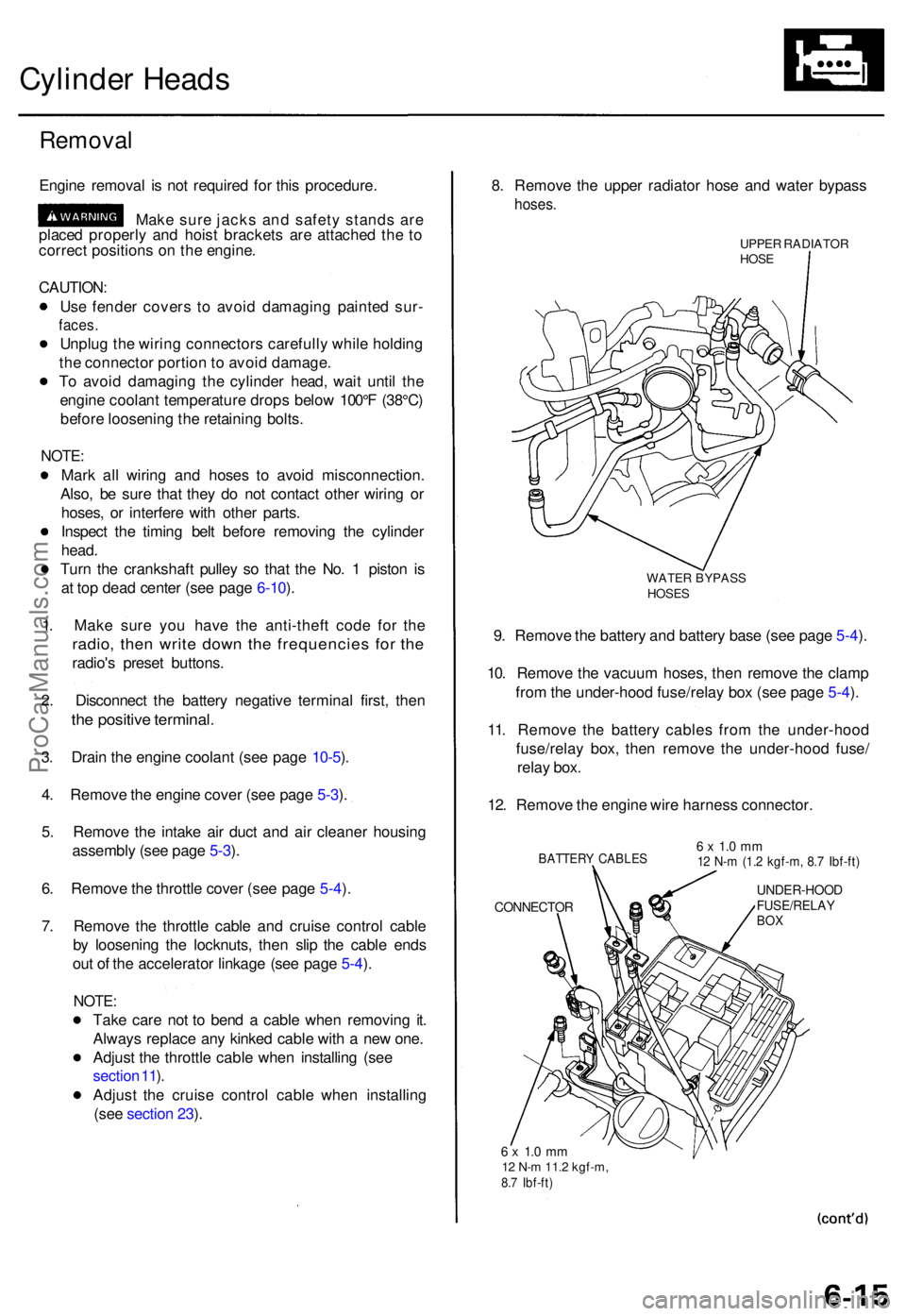
. Remov e th e uppe r radiato r hos e an d wate r bypas s
hoses.
UPPER RADIATO RHOSE
WATE R BYPAS SHOSES
9. Remov e th e batter y an d batter y bas e (se e pag e 5-4 ).
10 . Remov e th e vacuu m hoses , the n remov e th e clam p
fro m th e under-hoo d fuse/rela y bo x (se e pag e 5-4 ).
11 . Remov e th e batter y cable s fro m th e under-hoo d
fuse/rela y box , the n remov e th e under-hoo d fuse /
rela y box .
12 . Remov e th e engin e wir e harnes s connector .
BATTERY CABLE S
CONNECTO R
6 x 1. 0 m m12 N- m (1. 2 kgf-m , 8. 7 Ibf-ft )
UNDER-HOO DFUSE/RELAYBOX
6 x 1. 0 m m12 N- m 11. 2 kgf-m ,8.7 Ibf-ft )
ProCarManuals.com
Page 74 of 1771
Cylinder Head s
Remova l (cont'd )
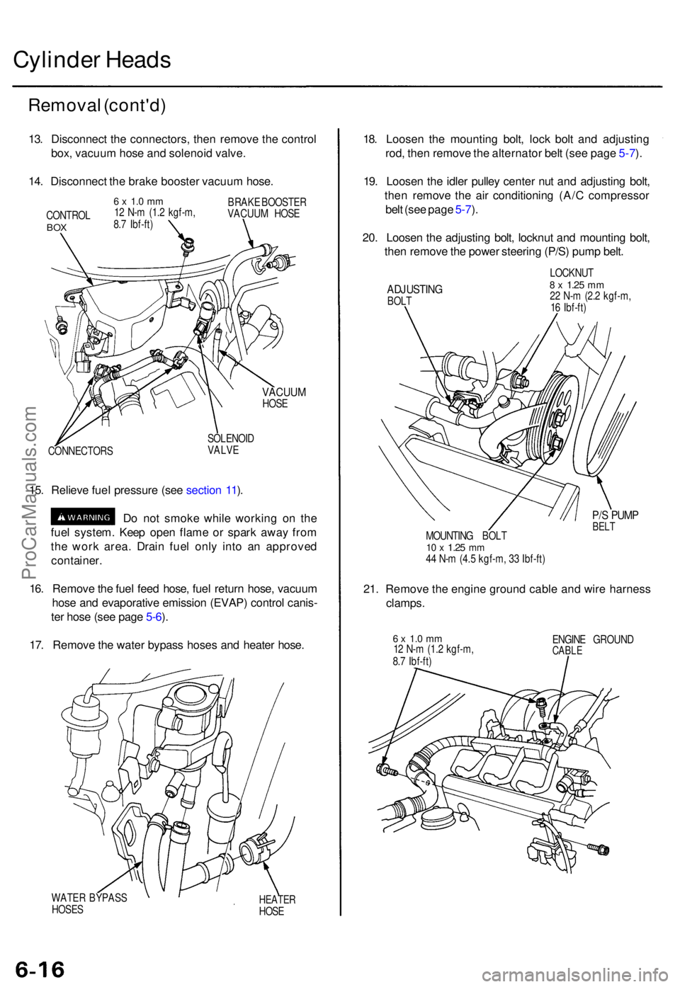
13. Disconnec t th e connectors , the n remov e th e contro l
box , vacuu m hos e an d solenoi d valve .
14 . Disconnec t th e brak e booste r vacuu m hose .
CONTRO LBOX
6 x 1. 0 m m12 N- m (1. 2 kgf-m ,
8. 7 Ibf-ft ) BRAK
E BOOSTE R
VACUU M HOS E
VACUU MHOSE
CONNECTOR S SOLENOI
D
VALVE
15. Reliev e fue l pressur e (se e sectio n 11 ).
D o no t smok e whil e workin g o n th e
fue l system . Kee p ope n flam e o r spar k awa y fro m
th e wor k area . Drai n fue l onl y int o a n approve d
container .
16 . Remov e th e fue l fee d hose , fue l retur n hose , vacuu m
hos e an d evaporativ e emissio n (EVAP ) contro l canis -
te r hos e (se e pag e 5-6 ).
17 . Remov e th e wate r bypas s hose s an d heate r hose .
WATE R BYPAS S
HOSE SHEATE RHOSE
18. Loose n th e mountin g bolt , loc k bol t an d adjustin g
rod , the n remov e th e alternato r bel t (se e pag e 5-7 ).
19 . Loose n th e idle r pulle y cente r nu t an d adjustin g bolt ,
the n remov e th e ai r conditionin g (A/ C compresso r
bel t (se e pag e 5-7 ).
20 . Loose n th e adjustin g bolt , locknu t an d mountin g bolt ,
the n remov e th e powe r steerin g (P/S ) pum p belt .
ADJUSTIN GBOLT LOCKNU
T
8 x 1.2 5 mm22 N- m (2. 2 kgf-m ,
1 6 Ibf-ft )
P/S PUM PBELTMOUNTIN G BOL T10 x 1.2 5 mm44 N- m (4. 5 kgf-m , 3 3 Ibf-ft )
21. Remov e th e engine ground cabl e an d wir e harnes s
clamps.
6 x 1. 0 m m12 N- m (1. 2 kgf-m ,
8. 7 Ibf-ft ) ENGIN
E GROUN DCABLE
ProCarManuals.com
Page 83 of 1771
Camshaft
Inspection (cont'd)
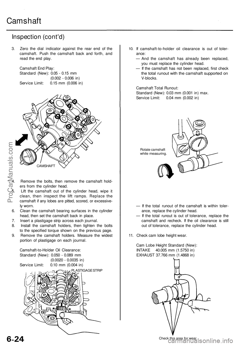
3. Zero the dial indicator against the rear end of the
camshaft. Push the camshaft back and forth, and
read the end play.
Camshaft End Play:
Standard (New): 0.05 - 0.15 mm
(0.002 - 0.006 in)
Service Limit: 0.15 mm (0.006 in)
4. Remove the bolts, then remove the camshaft hold-
ers from the cylinder head.
5. Lift the camshaft out of the cylinder head, wipe it
clean,
then
inspect
the
lift
ramps.
Replace
the
camshaft if any lobes are pitted, scored, or excessive-
ly worn.
6. Clean the camshaft bearing surfaces in the cylinder
head, then set the camshaft back in place.
7. Insert a plastigage strip across each journal.
8. Install the camshaft holders, then tighten the bolts
to the specified torque shown on the previous page.
9. Remove the camshaft holders. Measure the widest
portion of plastigage on each journal.
Camshaft-to-Holder Oil Clearance:
Standard (New): 0.050 - 0.089 mm
(0.0020 - 0.0035 in)
Service Limit: 0.10 mm (0.004 in)
PLASTIGAGE STRIP
10.
If camshaft-to-holder oil clearance is out of toler-
ance:
— And the camshaft has already been replaced,
you must replace the cylinder head.
— If the camshaft has not been replaced, first check
the total runout with the camshaft supported on
V-blocks.
Camshaft Total Runout:
Standard (New): 0.03 mm (0.001 in) max.
Service Limit: 0.04 mm (0.002 in)
Rotate camshaft
while measuring.
— If the total runout of the camshaft is within toler-
ance, replace the cylinder head.
— If the total runout is out of tolerance, replace the
camshaft and recheck. If the oil clearance is still
out of tolerance, replace the cylinder head.
11. Check cam lobe height wear.
Cam Lobe Height Standard (New):
INTAKE 40.005 mm (1.5750 in)
EXHAUST 37.766 mm (1.4868 in)
Check this area for wear.
CAMSHAFTProCarManuals.com
Page 92 of 1771
Reaming
NOTE: Fo r ne w valv e guide s only .
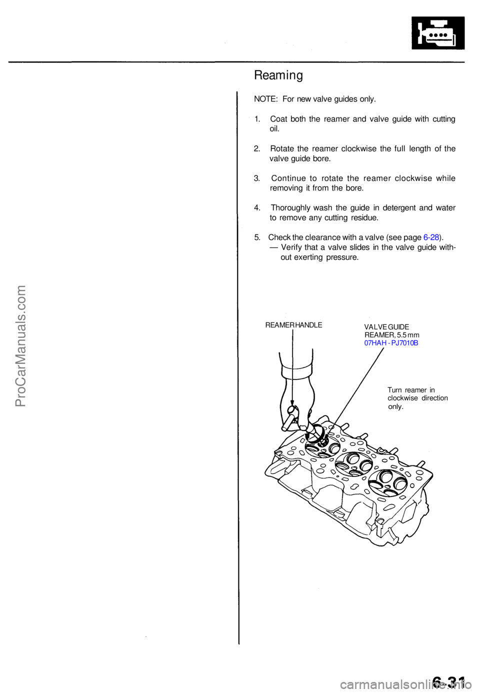
1 . Coa t bot h th e reame r an d valv e guid e wit h cuttin g
oil.
2. Rotat e th e reame r clockwis e th e ful l lengt h o f th e
valv e guid e bore .
3 . Continu e t o rotat e th e reame r clockwis e whil e
removin g i t fro m th e bore .
4 . Thoroughl y was h th e guid e i n detergen t an d wate r
t o remov e an y cuttin g residue .
5 . Chec k th e clearanc e wit h a valv e (se e pag e 6-28 ).
— Verif y tha t a valv e slide s i n th e valv e guid e with -
ou t exertin g pressure .
REAMER HANDL E
VALVE GUID E
REAMER , 5. 5 m m
07HA H - PJ7010 B
Tur n reame r i n
clockwis e directio n
only.
ProCarManuals.com
Page 96 of 1771
Cylinder Heads
Installation
Install th e cylinde r head s in th e revers e orde r o f removal .
NOTE:
Alway s us e ne w cylinde r hea d gaskets .
Cylinde r head s an d cylinde r bloc k surfac e mus t b e
clean .
Turn th e camshaft s s o th e pulle y locatin g pi n hole s
are a t th e top .
Turn th e crankshaf t s o th e No . 1 pisto n is a t TD C (se e
pag e 6-8 ).
Clea n th e oi l contro l orifice s befor e installing .
D o no t us e th e uppe r an d lowe r cover s t o stor e
remove d item .
Clea n th e uppe r an d lowe r cover s befor e installation .
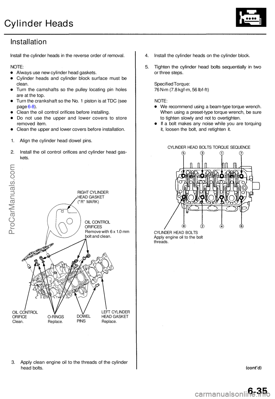
1 . Alig n th e cylinde r hea d dowe l pins .
2 . Instal l th e oi l contro l orifice s an d cylinde r hea d gas -
kets.
RIGH T CYLINDE RHEAD GASKE T("R" MARK )
OIL CONTRO LORIFICESRemove wit h 6 x 1. 0 m m
bol t an d clean .
OIL CONTRO LORIFICEClean.O-RING SReplace .
DOWELPINS
LEF T CYLINDE RHEAD GASKE TReplace.
3. Appl y clea n engin e oi l t o th e thread s o f th e cylinde r
hea d bolts . 4
. Instal l th e cylinde r head s o n th e cylinde r block .
5. Tighte n th e cylinde r hea d bolt s sequentiall y in tw o
or thre e steps .
Specifie d Torque :
7 6 N- m (7. 8 kgf-m , 5 6 Ibf-ft )
NOTE :
We recommen d usin g a beam-typ e torqu e wrench .
Whe n usin g a preset-typ e torqu e wrench , b e sur e
t o tighte n slowl y an d no t t o overtighten .
I f a bol t make s an y nois e whil e yo u ar e torquin g
it , loose n th e bolt , an d retighte n it .
CYLINDE R HEA D BOLT S TORQU E SEQUENC E
CYLINDER HEA D BOLT SApply engin e oi l t o th e bol tthreads .
ProCarManuals.com
Page 102 of 1771
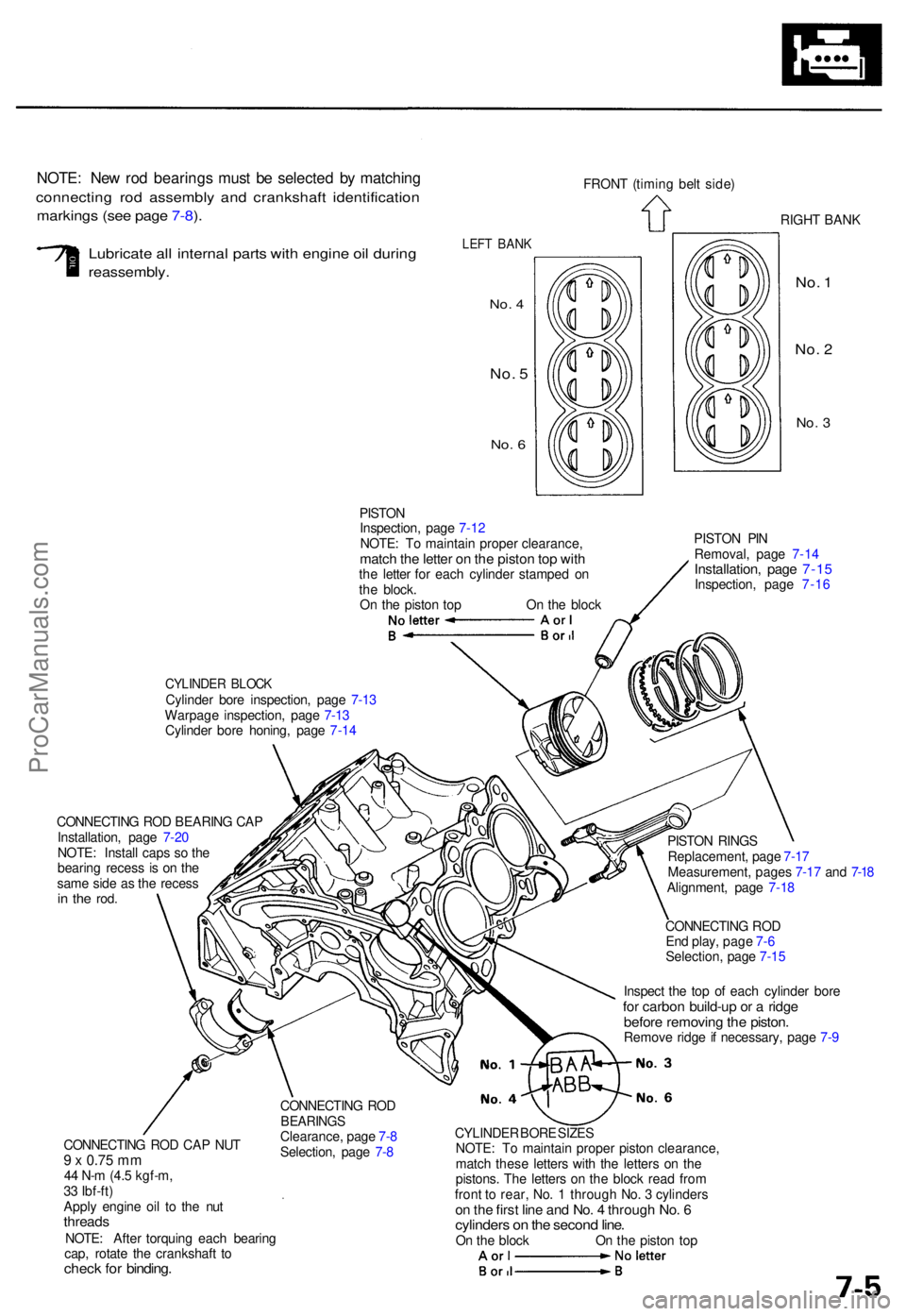
NOTE: Ne w ro d bearing s mus t b e selecte d b y matchin g
connectin g ro d assembl y an d crankshaf t identificatio n
markings (se e pag e 7-8 ).
FRON T (timin g bel t side )
RIGHT BAN K
Lubricat e al l interna l part s wit h engin e oi l during
reassembly .
LEFT BAN K
No. 4
No . 5
No . 6
No . 1
No . 2
No . 3
PISTO N
Inspection , pag e 7-1 2
NOTE : T o maintai n prope r clearance ,
match th e lette r o n th e pisto n to p wit hthe lette r fo r eac h cylinde r stampe d o n
th e block .
O n th e pisto n to p O n th e bloc k PISTO
N PI N
Removal , pag e 7-1 4Installation , pag e 7-1 5Inspection , pag e 7-1 6
CYLINDE R BLOC KCylinde r bor e inspection , pag e 7-1 3
Warpag e inspection , pag e 7-1 3
Cylinde r bor e honing , pag e 7-1 4
CONNECTIN G RO D BEARIN G CA P
Installation , pag e 7-2 0
NOTE : Instal l cap s s o th e
bearin g reces s i s o n th e
sam e sid e a s th e reces s
in th e rod .
CONNECTIN G RO D CA P NU T9 x 0.7 5 m m44 N- m (4. 5 kgf-m ,
3 3 Ibf-ft )
Appl y engin e oi l t o th e nu t
thread sNOTE: Afte r torquin g eac h bearin g
cap , rotat e th e crankshaf t t o
chec k fo r binding .
CONNECTIN G RO DBEARING SClearance , pag e 7- 8
Selection , pag e 7- 8 PISTO
N RING S
Replacement , pag e 7-1 7
Measurement , page s 7-1 7 an d 7-1 8
Alignment , pag e 7-1 8
CONNECTIN G RO D
En d play , pag e 7- 6
Selection , pag e 7-1 5
Inspec t th e to p o f eac h cylinde r bor e
for carbo n build-u p o r a ridg ebefor e removin g th e piston .Remov e ridg e if necessary , pag e 7- 9
CYLINDE R BOR E SIZE S
NOTE : T o maintai n prope r pisto n clearance ,
matc h thes e letter s wit h th e letter s o n th e
pistons . Th e letter s o n th e bloc k rea d fro m
fron t t o rear , No . 1 throug h No . 3 cylinder s
on th e firs t lin e an d No . 4 throug h No . 6cylinder s o n th e secon d line .On th e bloc k O n th e pisto n to p
ProCarManuals.com