1994 JEEP CHEROKEE ECU
[x] Cancel search: ECUPage 1495 of 1784
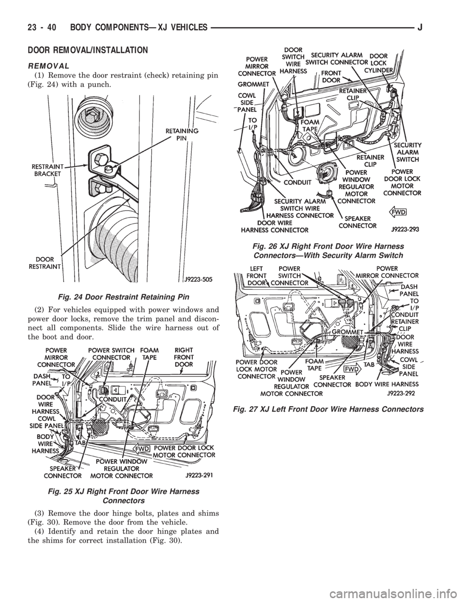
DOOR REMOVAL/INSTALLATION
REMOVAL
(1) Remove the door restraint (check) retaining pin
(Fig. 24) with a punch.
(2) For vehicles equipped with power windows and
power door locks, remove the trim panel and discon-
nect all components. Slide the wire harness out of
the boot and door.
(3) Remove the door hinge bolts, plates and shims
(Fig. 30). Remove the door from the vehicle.
(4) Identify and retain the door hinge plates and
the shims for correct installation (Fig. 30).
Fig. 24 Door Restraint Retaining Pin
Fig. 25 XJ Right Front Door Wire Harness
Connectors
Fig. 26 XJ Right Front Door Wire Harness
ConnectorsÐWith Security Alarm Switch
Fig. 27 XJ Left Front Door Wire Harness Connectors
23 - 40 BODY COMPONENTSÐXJ VEHICLESJ
Page 1510 of 1784
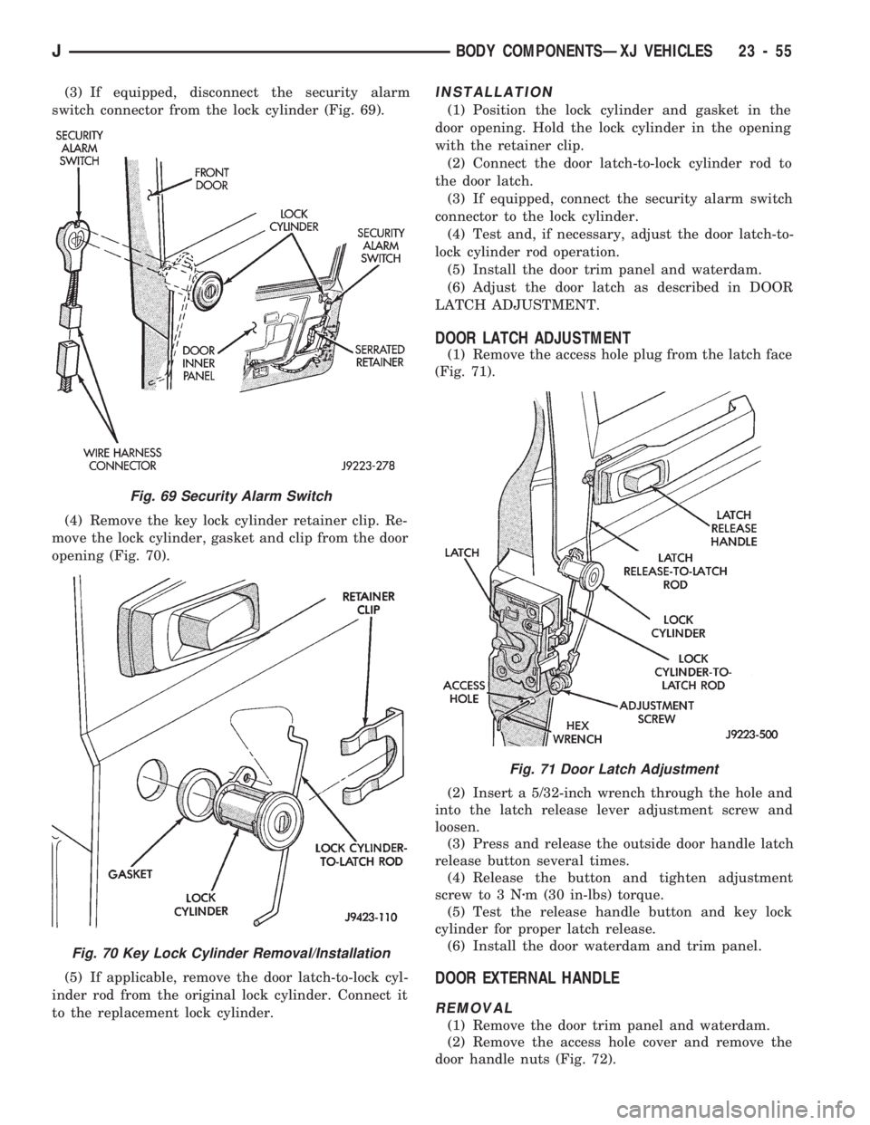
(3) If equipped, disconnect the security alarm
switch connector from the lock cylinder (Fig. 69).
(4) Remove the key lock cylinder retainer clip. Re-
move the lock cylinder, gasket and clip from the door
opening (Fig. 70).
(5) If applicable, remove the door latch-to-lock cyl-
inder rod from the original lock cylinder. Connect it
to the replacement lock cylinder.INSTALLATION
(1) Position the lock cylinder and gasket in the
door opening. Hold the lock cylinder in the opening
with the retainer clip.
(2) Connect the door latch-to-lock cylinder rod to
the door latch.
(3) If equipped, connect the security alarm switch
connector to the lock cylinder.
(4) Test and, if necessary, adjust the door latch-to-
lock cylinder rod operation.
(5) Install the door trim panel and waterdam.
(6) Adjust the door latch as described in DOOR
LATCH ADJUSTMENT.
DOOR LATCH ADJUSTMENT
(1) Remove the access hole plug from the latch face
(Fig. 71).
(2) Insert a 5/32-inch wrench through the hole and
into the latch release lever adjustment screw and
loosen.
(3) Press and release the outside door handle latch
release button several times.
(4) Release the button and tighten adjustment
screw to 3 Nzm (30 in-lbs) torque.
(5) Test the release handle button and key lock
cylinder for proper latch release.
(6) Install the door waterdam and trim panel.
DOOR EXTERNAL HANDLE
REMOVAL
(1) Remove the door trim panel and waterdam.
(2) Remove the access hole cover and remove the
door handle nuts (Fig. 72).
Fig. 71 Door Latch Adjustment
Fig. 69 Security Alarm Switch
Fig. 70 Key Lock Cylinder Removal/Installation
JBODY COMPONENTSÐXJ VEHICLES 23 - 55
Page 1520 of 1784
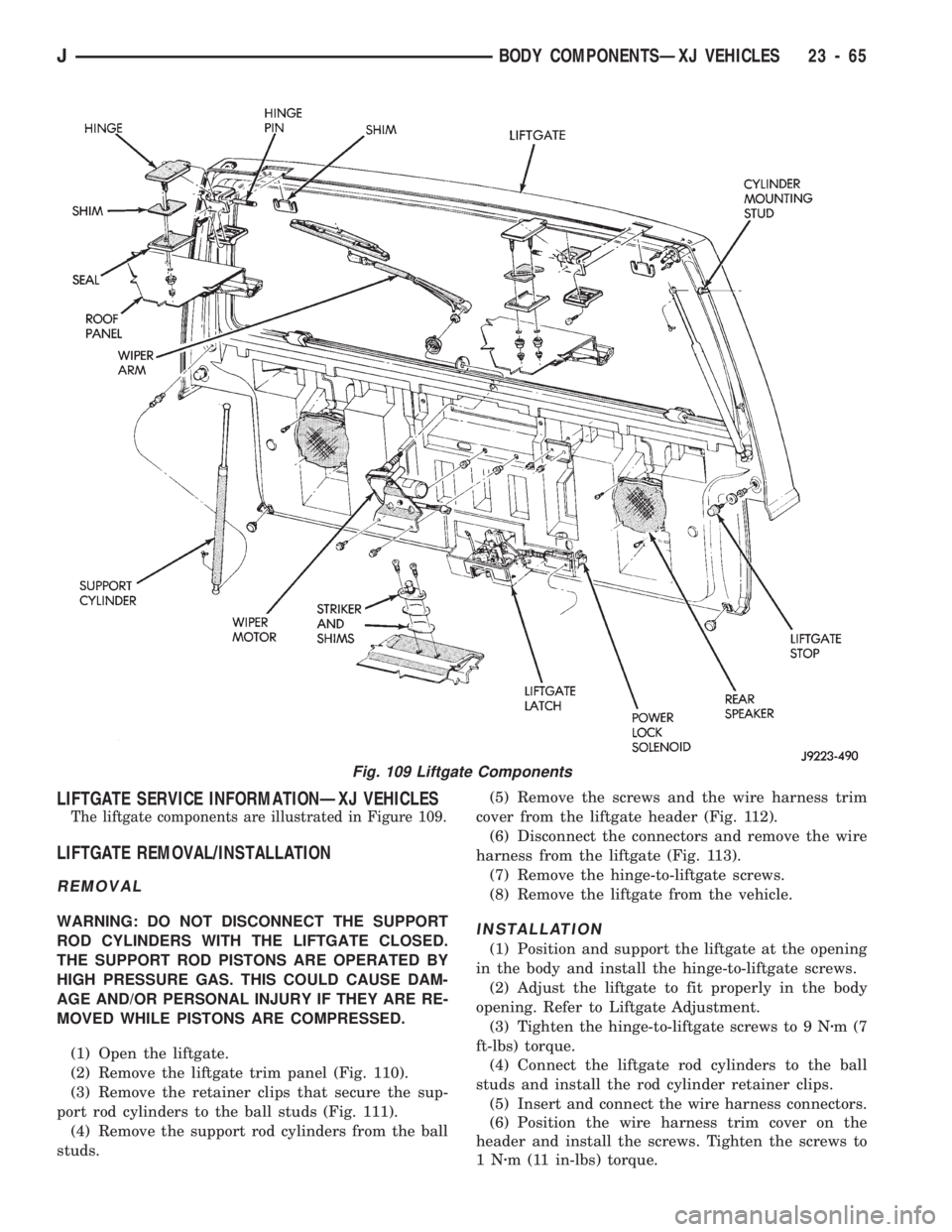
LIFTGATE SERVICE INFORMATIONÐXJ VEHICLES
The liftgate components are illustrated in Figure 109.
LIFTGATE REMOVAL/INSTALLATION
REMOVAL
WARNING: DO NOT DISCONNECT THE SUPPORT
ROD CYLINDERS WITH THE LIFTGATE CLOSED.
THE SUPPORT ROD PISTONS ARE OPERATED BY
HIGH PRESSURE GAS. THIS COULD CAUSE DAM-
AGE AND/OR PERSONAL INJURY IF THEY ARE RE-
MOVED WHILE PISTONS ARE COMPRESSED.
(1) Open the liftgate.
(2) Remove the liftgate trim panel (Fig. 110).
(3) Remove the retainer clips that secure the sup-
port rod cylinders to the ball studs (Fig. 111).
(4) Remove the support rod cylinders from the ball
studs.(5) Remove the screws and the wire harness trim
cover from the liftgate header (Fig. 112).
(6) Disconnect the connectors and remove the wire
harness from the liftgate (Fig. 113).
(7) Remove the hinge-to-liftgate screws.
(8) Remove the liftgate from the vehicle.INSTALLATION
(1) Position and support the liftgate at the opening
in the body and install the hinge-to-liftgate screws.
(2) Adjust the liftgate to fit properly in the body
opening. Refer to Liftgate Adjustment.
(3) Tighten the hinge-to-liftgate screws to 9 Nzm(7
ft-lbs) torque.
(4) Connect the liftgate rod cylinders to the ball
studs and install the rod cylinder retainer clips.
(5) Insert and connect the wire harness connectors.
(6) Position the wire harness trim cover on the
header and install the screws. Tighten the screws to
1Nzm (11 in-lbs) torque.
Fig. 109 Liftgate Components
JBODY COMPONENTSÐXJ VEHICLES 23 - 65
Page 1524 of 1784
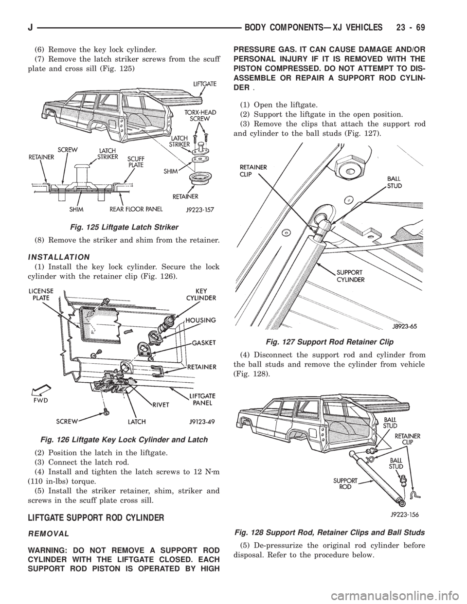
(6) Remove the key lock cylinder.
(7) Remove the latch striker screws from the scuff
plate and cross sill (Fig. 125)
(8) Remove the striker and shim from the retainer.
INSTALLATION
(1) Install the key lock cylinder. Secure the lock
cylinder with the retainer clip (Fig. 126).
(2) Position the latch in the liftgate.
(3) Connect the latch rod.
(4) Install and tighten the latch screws to 12 Nzm
(110 in-lbs) torque.
(5) Install the striker retainer, shim, striker and
screws in the scuff plate cross sill.
LIFTGATE SUPPORT ROD CYLINDER
REMOVAL
WARNING: DO NOT REMOVE A SUPPORT ROD
CYLINDER WITH THE LIFTGATE CLOSED. EACH
SUPPORT ROD PISTON IS OPERATED BY HIGHPRESSURE GAS. IT CAN CAUSE DAMAGE AND/OR
PERSONAL INJURY IF IT IS REMOVED WITH THE
PISTON COMPRESSED. DO NOT ATTEMPT TO DIS-
ASSEMBLE OR REPAIR A SUPPORT ROD CYLIN-
DER.
(1) Open the liftgate.
(2) Support the liftgate in the open position.
(3) Remove the clips that attach the support rod
and cylinder to the ball studs (Fig. 127).
(4) Disconnect the support rod and cylinder from
the ball studs and remove the cylinder from vehicle
(Fig. 128).
(5) De-pressurize the original rod cylinder before
disposal. Refer to the procedure below.
Fig. 127 Support Rod Retainer Clip
Fig. 128 Support Rod, Retainer Clips and Ball Studs
Fig. 125 Liftgate Latch Striker
Fig. 126 Liftgate Key Lock Cylinder and Latch
JBODY COMPONENTSÐXJ VEHICLES 23 - 69
Page 1525 of 1784
INSTALLATION
(1) Connect the replacement support rod and cylin-
der to the ball studs.
(2) Secure the support rod and cylinder to the ball
studs with the retainer clips.
(3) Remove the support from the liftgate and test
the operation of the support rod.
LIFTGATE SUPPORT ROD CYLINDER DISPOSAL
WARNING: SAFETY GOGGLES MUST BE WORN
DURING THE DISPOSAL PROCEDURE. THE HIGH
PRESSURE GAS CHARGE IN THE SUPPORT ROD
CYLINDERS WILL BE RELEASED DURING THE
PROCEDURE.
(1) Remove the support rod cylinder(s) from the
liftgate.
(2) Position the support rod cylinder horizontally
in a vise and clamp the cylinder securely.
(3) Wrap the cylinder with 4-5 layers of shop tow-
els.
(4) Measure 1 and 1/2 inches inward from the end
of the cylinder. Mark this location on the towels with
chalk. The cylinder will be punctured at this location
to release the gas charge.
(5) Use a punch and hammer to puncture cylinder.
Force the punch through towels and into the cylinder
with a hammer. Continue striking the punch until
the gas begins to escapebut do not remove the
punch.
(6) Hold the towels and punch in position until all
the gas has escaped. Complete de-pressurization will
require about 4 to 10 seconds. After all the gas has
escaped, slowly remove the punch.
(7) Hold a towel over the hole in cylinder and press
the support rod piston all the way into the cylinder
to purge remaining oil.
(8) Remove the support rod cylinder from the vise
and discard it.
(9) If both support rod cylinders are being re-
placed, repeat this procedure for the remaining cylin-
der.
LIFTGATE SUPPORT ROD BALL STUD
REPLACEMENT
REMOVAL
(1) Open the liftgate.
(2) Support the liftgate in the open position.
(3) Remove the retainer clip that attaches the sup-
port rod and cylinder to the ball stud.
(4) Disconnect the support rod from the ball stud.
(5) Remove the ball stud from the liftgate with a
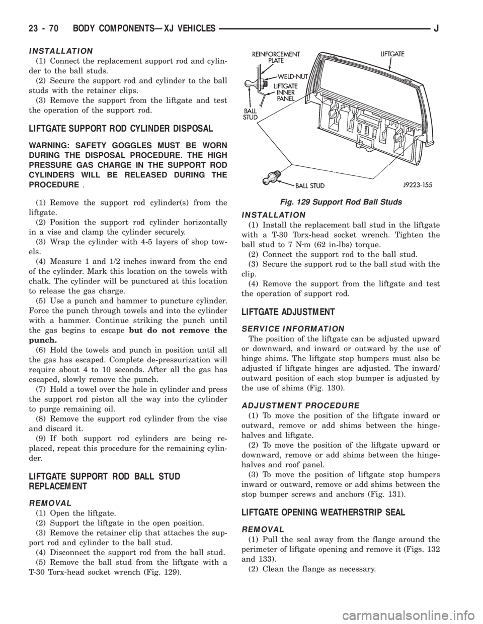
T-30 Torx-head socket wrench (Fig. 129).
INSTALLATION
(1) Install the replacement ball stud in the liftgate
with a T-30 Torx-head socket wrench. Tighten the
ball stud to 7 Nzm (62 in-lbs) torque.
(2) Connect the support rod to the ball stud.
(3) Secure the support rod to the ball stud with the
clip.
(4) Remove the support from the liftgate and test
the operation of support rod.
LIFTGATE ADJUSTMENT
SERVICE INFORMATION
The position of the liftgate can be adjusted upward
or downward, and inward or outward by the use of
hinge shims. The liftgate stop bumpers must also be
adjusted if liftgate hinges are adjusted. The inward/
outward position of each stop bumper is adjusted by
the use of shims (Fig. 130).
ADJUSTMENT PROCEDURE
(1) To move the position of the liftgate inward or
outward, remove or add shims between the hinge-
halves and liftgate.
(2) To move the position of the liftgate upward or
downward, remove or add shims between the hinge-
halves and roof panel.
(3) To move the position of liftgate stop bumpers
inward or outward, remove or add shims between the
stop bumper screws and anchors (Fig. 131).
LIFTGATE OPENING WEATHERSTRIP SEAL
REMOVAL
(1) Pull the seal away from the flange around the
perimeter of liftgate opening and remove it (Figs. 132
and 133).
(2) Clean the flange as necessary.
Fig. 129 Support Rod Ball Studs
23 - 70 BODY COMPONENTSÐXJ VEHICLESJ
Page 1550 of 1784
(3) Tilt instrument panel forward and tighten the
I/P-to-side cowl panel screws and ground wire.
(4) Position lower section of the instrument panel
at upper section.
(5) Install screws in lower section of the instru-
ment panel. Tighten screws securely.
(6) Install the park brake and screw in lower sec-
tion of the instrument panel. Tighten screw securely.
(7) Install steering column cover insert on instru-
ment panel.
(8) Install the defroster duct bezel on the instru-
ment panel.
(9) Install the defroster duct bezel on the instru-
ment panel.
I/P TWEETER SPEAKER/COURTESY LAMP
SUPPORT BRACKET
REMOVAL
(1) Remove the park brake retaining screw from
the lower section of the instrument panel.
(2) Remove the retaining screws from the lower
section of the instrument panel.
(3) Remove the lower section of the instrument
panel from the upper section.
(4) Disconnect the wire harness connector and re-
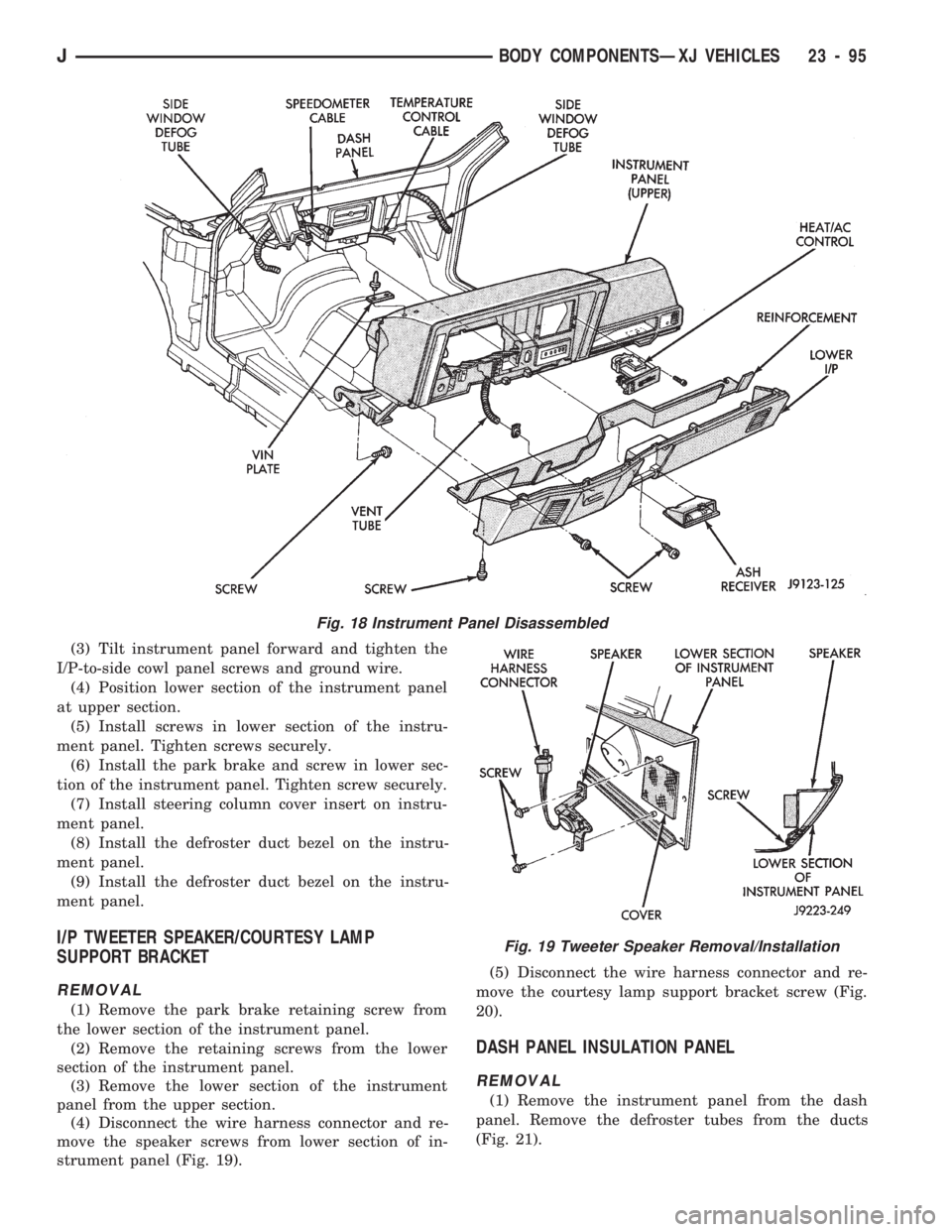
move the speaker screws from lower section of in-
strument panel (Fig. 19).(5) Disconnect the wire harness connector and re-
move the courtesy lamp support bracket screw (Fig.
20).
DASH PANEL INSULATION PANEL
REMOVAL
(1) Remove the instrument panel from the dash
panel. Remove the defroster tubes from the ducts
(Fig. 21).
Fig. 18 Instrument Panel Disassembled
Fig. 19 Tweeter Speaker Removal/Installation
JBODY COMPONENTSÐXJ VEHICLES 23 - 95
Page 1589 of 1784
EXTERIOR COMPONENTS
INDEX
page page
Battery Tray........................... 140
Body Extension Panels and FasciasÐYJ
Renegade Vehicles..................... 147
Body Side Step Moulding................. 145
Body Stripes/Decals..................... 153
Cowl Grille and Screen................... 139
Cowl Weatherstrip Seal................... 139
Exterior Nameplates (Adhesive-Backed)....... 158
External Spare/Wheel Tire Carrier........... 172
Fender Flare........................... 144
Fender Inner Splash Shields............... 147
Fender Splash Aprons.................... 147
Fenders............................... 141
Fog LampÐYJ Renegade Vehicles.......... 150
Front Fascia and Skid PlateÐYJ Renegade
Vehicles............................. 148
Front Fender Extension PanelÐYJ Renegade
Vehicles............................. 149
Fuel Filler Protector/Nozzle................ 158
Half Metal Door Mirror (External)............ 158
Hard Top Liftgate Glass.................. 162
Hard Top Repair........................ 165
Hard Top Roof Vent..................... 165
Hard Top Service....................... 164
Hard Top Service Information.............. 164Hood................................. 137
Hood Alignment......................... 138
Hood Insulator Panel..................... 138
Hood Safety Latch....................... 139
Liftgate Glass Weatherstrip Seal Replacement . . 163
Radiator Grille Applique................... 134
Rear Fascia and Skid PlateÐYJ Renegade
Vehicles............................. 152
Rear Quarter Extension PanelÐYJ Renegade
Vehicles............................. 151
Rocker Extension PanelÐYJ Renegade
Vehicles............................. 150
Soft Top Service........................ 167
Soft Top Service Information............... 166
Sport Bar............................. 171
Tailgate Adjustment...................... 160
Tailgate Hinge.......................... 159
Tailgate Latch and Release Handle.......... 160
Tailgate Latch Striker..................... 161
Tailgate Lock Cylinder.................... 160
Tailgate Service......................... 159
Tailgate Service Information................ 159
Tailgate Weatherstrip Seal................. 161
Wheelhouse Splash Liners................ 146
RADIATOR GRILLE APPLIQUE
REMOVAL
(1) Raise the hood.
(2) Remove the headlamp bezels (Fig. 1).
(3) Remove the headlamp bulb retainer screws
(Fig. 2).
(4) Disconnect and remove the headlamps and
buckets as a unit (Fig. 2).
(5) Remove the parking lamp retaining screws
(Fig. 2).
(6) Disconnect the wire harness connectors and re-
move the parking lamps (Fig. 2).
(7) Remove the front crossmember cover.
(8) Remove the retaining screws and the bumper
inserts at the top of the grille panel (Fig. 1).
(9) Detach the grille applique from the grille panel
(Fig. 1).
(10) Remove the double faced foam adhesive tape
at the bottom of the grille applique (Fig. 1).
INSTALLATION
(1) Install double faced foam tape at the bottom,
interior side of the grille applique (Fig. 1).
(2) Position the grille applique over the grille
panel and press inward along the bottom where the
tape is located (Fig. 1).
(3) Install the grille applique retaining screws and
the bumper inserts (Fig. 1).(4) Connect the wire harness connectors and posi-
tion the headlamp buckets and headlamps in the
grille panel (Fig. 2).
(5) Install the headlamp bulb retainer and the
screws (Fig. 1). Tighten the screws to 2 Nzm (18 in-
lbs) torque.
(6) Install the headlamp bezels and the retaining
screws (Fig. 1). Tighten the screws securely.
(7) Connect the wire harness connectors and in-
stall the parking lamps (Fig. 2).
(8) Install the parking lamp retaining screws.
Tighten the screws to 2 Nzm (18 in-lbs) torque.
(9) Close the hood.
(10) Install the front crossmember cover.
23 - 134 BODY COMPONENTSÐXJ VEHICLESJ
Page 1619 of 1784
(5) Carefully separate the weatherstrip seal from
the rear panels and the hard top (Fig. 91).
(6) Remove the residual adhesive from the seal
contact areas.
INSTALLATION
(1) Remove the tape cover and position the lift-
gate-to-tailgate weatherstrip seal at the bottom of
the liftgate glass (Fig. 91).
(2) Carefully insert the retainers into the holes
and press the seal against the bottom of the liftgate
glass (Fig. 91).
(3) Install the liftgate-to-tailgate weatherstrip seal
screws (Fig. 91). Tighten the screws securely.
(4) Apply weatherstrip adhesive to the hard top
weatherstrip seal as indicated in Figure 91.
(5) Carefully position the weatherstrip seal on the
rear panels and the hard top (Fig. 91).
(6) Press the seal onto the hard top flange and en-
sure that it is correctly seated on the flange (Fig. 91).
(7) Install the seal retaining screws in the rear
panels and tighten them securely (Fig. 91).
HARD TOP SERVICE INFORMATION
The following service procedures include:
²hard top removal/installation, and
²hard top repair procedures.
The hard top is constructed of compressed molded
fiberglass and painted to a special spatter paint. The
hard top can be removed for service access or for
other purposes.
HARD TOP SERVICE
REMOVAL
CAUTION: When removing the hard top, avoid dam-
aging the foam sealant between the hard top and
body panels.
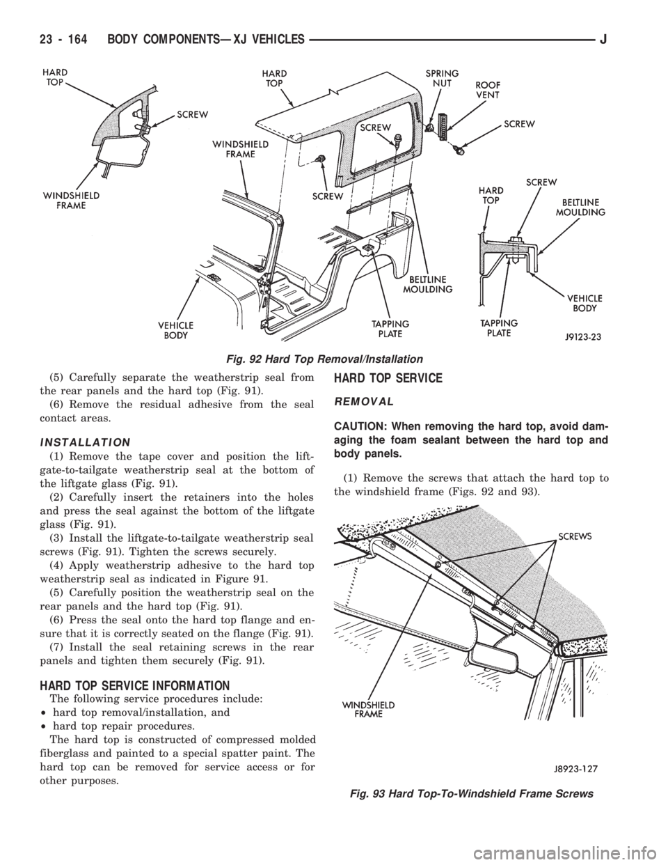
(1) Remove the screws that attach the hard top to
the windshield frame (Figs. 92 and 93).
Fig. 92 Hard Top Removal/Installation
Fig. 93 Hard Top-To-Windshield Frame Screws
23 - 164 BODY COMPONENTSÐXJ VEHICLESJ