1994 JEEP CHEROKEE wheel bolts
[x] Cancel search: wheel boltsPage 26 of 1784

DRAINING ATF/FILTER REMOVAL
Drain the automatic transmission fluid (ATF) im-
mediately after stopping the engine (before the ATF
cools).
(1) Raise and support the vehicle.
(2) Loosen the transmission pan bolts and drain
the original ATF into an appropriate container. Re-
move the pan bolts, the pan and the gasket.
Care should be exercised when disposing used
ATF after it has been drained from a vehicle
transmission.
(3) Remove the screws and the ATF filter (Fig. 8).
Discard the filter.
FILTER INSTALLATION/ATF RE-FILL
(1) Install a replacement ATF filter. Tighten the
screws with 4 NIm (35 in. lbs.) torque.
(2) Clean the pan thoroughly. Install a replace-
ment gasket on the pan. Install the pan with the at-
taching bolts:
²model AW-4 transmission Ð tighten the pan bolts
with 7 NIm (60 in. lbs.) torque; and
²model 998 transmission Ð tighten the pan bolts
with 17 NIm (150 in. lbs.) torque.
(3) Remove the support and lower the vehicle.
(4) Pour approximately 4.7 liters (5 quarts) of ATF
into the filler tube. Use MerconŸ ATF for AW-4 au-
tomatic transmissions. Use MOPAR ATF PLUS type
7176 or equivalent, for 998 automatic transmissions.
(5) Place a block in front of and at the rear of one
wheel/tire to prevent vehicle movement.
(6) Start the engine and allow it to idle a few min-
utes.
(7) Apply the brake pedal and engage the parking
brake. Move the transmission selector lever through
all positions, then place the selector lever in NEU-
TRAL position.(8) With the transmission at normal operating
temperature, observe the ATF level on the dipstick.
Add ATF (if necessary) to raise the level to the
FULL mark on the dipstick.Only 0.5 liter (1.0 pint)
will raise the level from the ADD mark to the
FULL mark when the ATF is at normal operat-
ing temperature.
(9) Inspect for fluid leaks and correct as necessary.
(10) Remove the wheel/tire blocks.
TRANSFER CASE
RECOMMENDED MAINTENANCE
The fluid (ATF) level in transfer cases should be
determined at the same time as the engine oil is
changed and the oil filter is replaced. Add ATF as
necessary.
In addition, transfer case ATF should be changed
after each 48 000-km (30,000-miles) interval of vehi-
cle operation has elapsed.
FLUID SPECIFICATIONS
If it is necessary to add fluid to a transfer case (or
when the fluid is changed), use MOPAR ATF PLUS
type 7176 or an equivalent MerconŸ/Dexron IIŸ
ATF.
FLUID LEVEL
The transfer case fill-hole plug is located at the
rear of the housing (Fig. 9).
Determine the transfer case fluid (ATF) level ac-
cording to the following procedure.
(1) Raise and support the vehicle.
(2) Remove the fill-hole plug from the transfer
case. The ATF level should be at the bottom edge of
the fill hole. The level can be slightly below the bot-
tom edge of the fill hole if the fluid is cold.
Fig. 9 Transfer CaseÐTypical
Fig. 8 ATF FilterÐTypical
JLUBRICATION AND MAINTENANCE 0 - 25
Page 38 of 1784
FRONT SUSPENSION AND AXLE
CONTENTS
page page
AXLE NOISE/VIBRATION DIAGNOSIS....... 16
FRONT WHEEL ALIGNMENT............... 5
GENERAL INFORMATION.................. 1
MODEL 30 AXLE AND TUBE AXLE (2WD) . . 20TORQUE SPECIFICATIONS................ 47
XJ FRONT SUSPENSION................. 10
YJ FRONT SUSPENSION................. 13
GENERAL INFORMATION
FRONT SUSPENSION
XJ VEHICLES
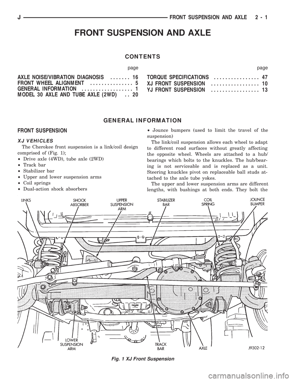
The Cherokee front suspension is a link/coil design
comprised of (Fig. 1);
²Drive axle (4WD), tube axle (2WD)
²Track bar
²Stabilizer bar
²Upper and lower suspension arms
²Coil springs
²Dual-action shock absorbers²Jounce bumpers (used to limit the travel of the
suspension)
The link/coil suspension allows each wheel to adapt
to different road surfaces without greatly affecting
the opposite wheel. Wheels are attached to a hub/
bearings which bolts to the knuckles. The hub/bear-
ing is not serviceable and is replaced as a unit.
Steering knuckles pivot on replaceable ball studs at-
tached to the axle tube yokes.
The upper and lower suspension arms are different
lengths, with bushings at both ends. They bolt the
Fig. 1 XJ Front Suspension
JFRONT SUSPENSION AND AXLE 2 - 1
Page 45 of 1784
TOE POSITIONÐXJ VEHICLES
The wheel toe position adjustment should be the fi-
nal adjustment.
(1) Start the engine and turn wheels both ways be-
fore straightening the wheels. Secure the steering
wheel with the front wheels in the straight-ahead po-
sition.
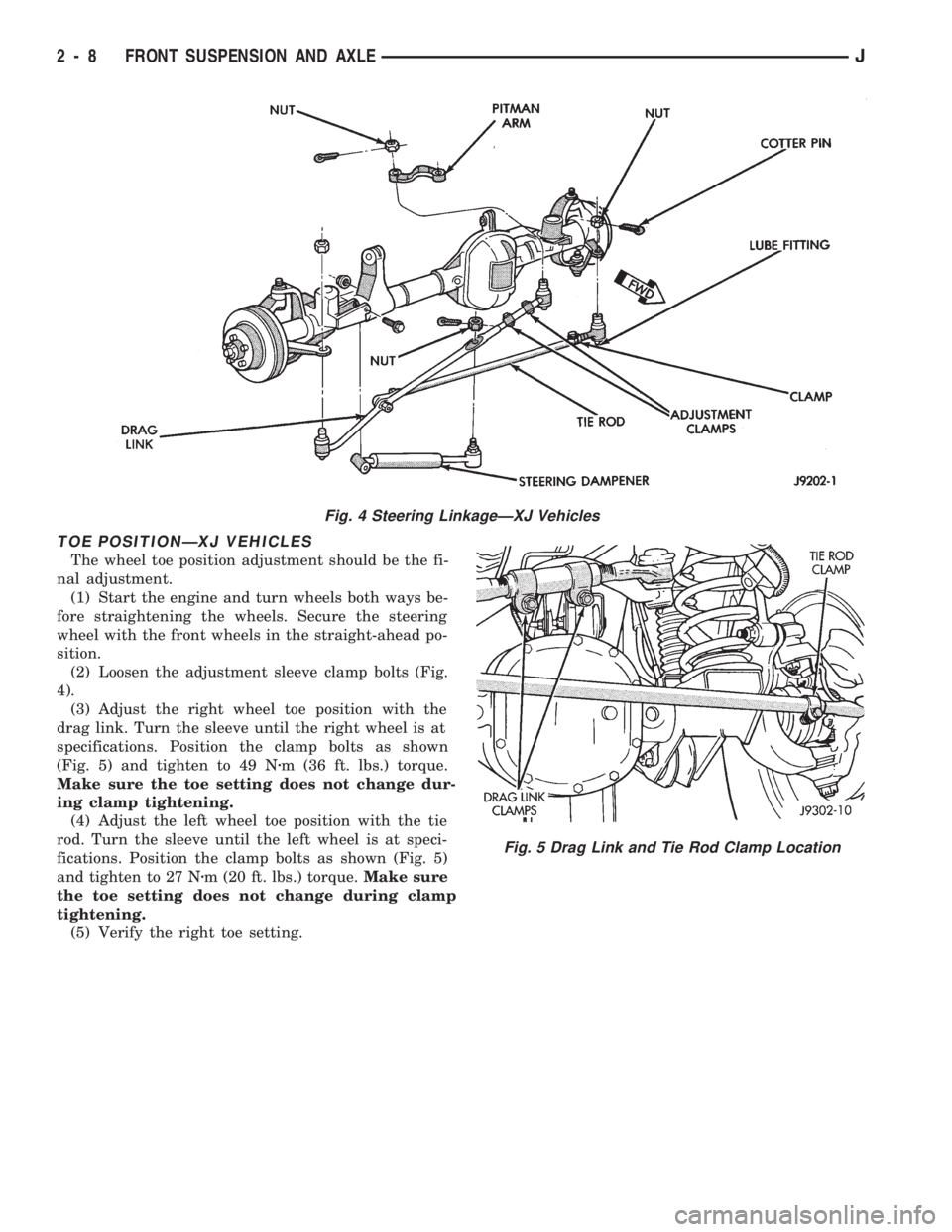
(2) Loosen the adjustment sleeve clamp bolts (Fig.
4).
(3) Adjust the right wheel toe position with the
drag link. Turn the sleeve until the right wheel is at
specifications. Position the clamp bolts as shown
(Fig. 5) and tighten to 49 Nzm (36 ft. lbs.) torque.
Make sure the toe setting does not change dur-
ing clamp tightening.
(4) Adjust the left wheel toe position with the tie
rod. Turn the sleeve until the left wheel is at speci-
fications. Position the clamp bolts as shown (Fig. 5)
and tighten to 27 Nzm (20 ft. lbs.) torque.Make sure
the toe setting does not change during clamp
tightening.
(5) Verify the right toe setting.
Fig. 4 Steering LinkageÐXJ Vehicles
Fig. 5 Drag Link and Tie Rod Clamp Location
2 - 8 FRONT SUSPENSION AND AXLEJ
Page 46 of 1784
TOE POSITIONÐYJ VEHICLES
The wheel toe position should be the final front
wheel alignment adjustment. In all instances follow
the equipment manufacturer's recommended proce-
dure.
(1) Secure the steering wheel with the front wheels
in the straight-ahead position. For vehicles equipped
with power steering, start the engine before straight-
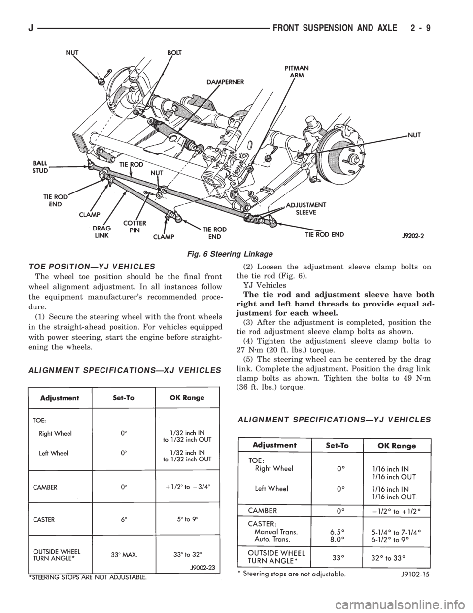
ening the wheels.(2) Loosen the adjustment sleeve clamp bolts on
the tie rod (Fig. 6).
YJ Vehicles
The tie rod and adjustment sleeve have both
right and left hand threads to provide equal ad-
justment for each wheel.
(3) After the adjustment is completed, position the
tie rod adjustment sleeve clamp bolts as shown.
(4) Tighten the adjustment sleeve clamp bolts to
27 Nzm (20 ft. lbs.) torque.
(5) The steering wheel can be centered by the drag
link. Complete the adjustment. Position the drag link
clamp bolts as shown. Tighten the bolts to 49 Nzm
(36 ft. lbs.) torque.
Fig. 6 Steering Linkage
ALIGNMENT SPECIFICATIONSÐXJ VEHICLES
ALIGNMENT SPECIFICATIONSÐYJ VEHICLES
JFRONT SUSPENSION AND AXLE 2 - 9
Page 48 of 1784
INSTALLATION
(1) Inspect stabilizer bar bushings ( Fig. 2). Re-
place bushings if cracked, cut, distorted, or worn.
(2) Position the stabilizer bar on the frame rail
and install the bushings and clamps. Ensure the bar
is centered with equal spacing on both sides. Tighten
the bolts to 75 Nzm (40 ft. lbs.).
(3) Install the links and grommets onto the stabi-
lizer bar and axle brackets (Fig. 2). Tighten the nut
at the connecting links at the axle bracket to 95 Nzm
(70 ft. lbs.) torque.
(4) Tighten the stabilizer bar to connecting link
nut to 36 Nzm (27 ft. lbs.) torque.
(5) Remove the supports and lower the vehicle.
UPPER SUSPENSION ARM
REMOVAL
(1) Raise and support the vehicle.
(2) Remove the upper suspension arm nut and bolt
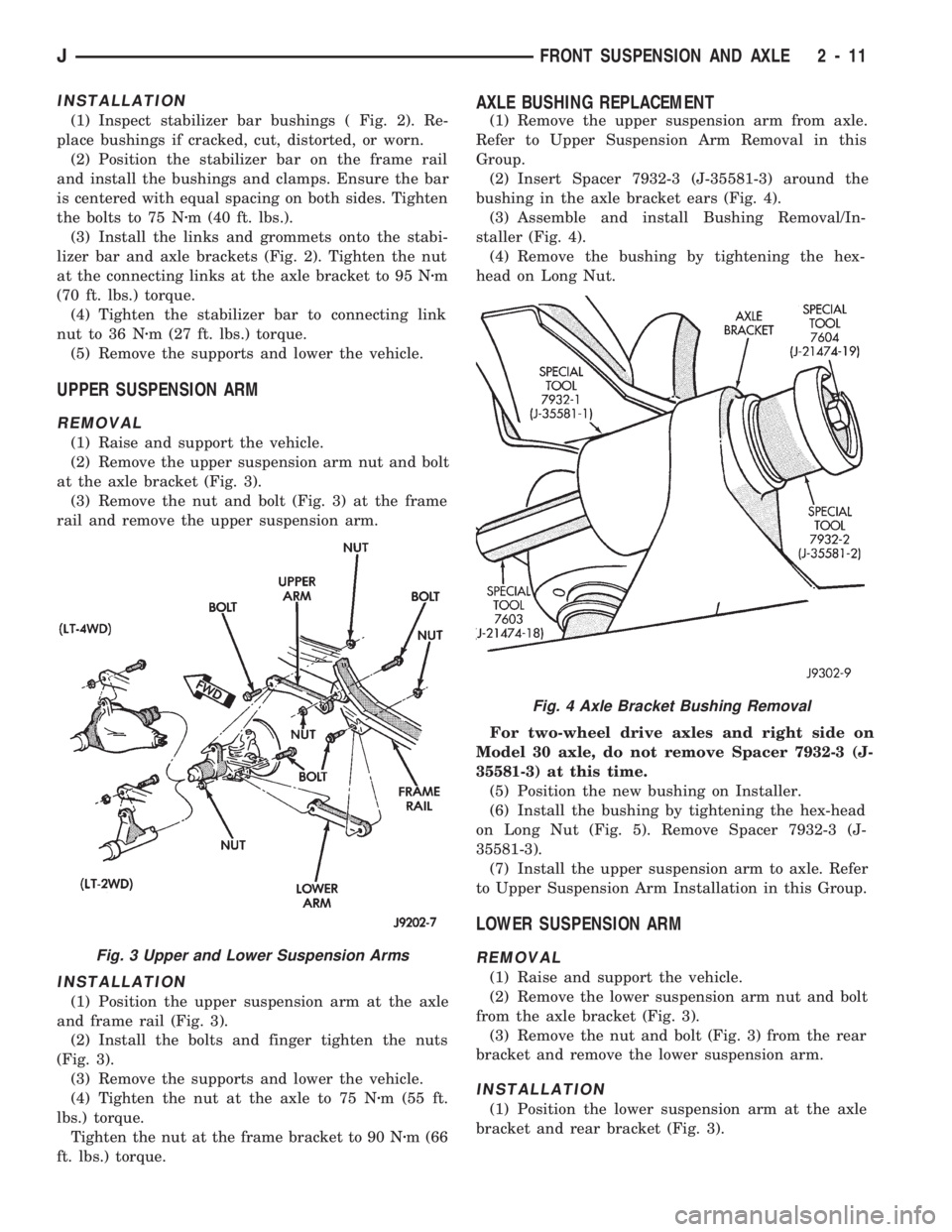
at the axle bracket (Fig. 3).
(3) Remove the nut and bolt (Fig. 3) at the frame
rail and remove the upper suspension arm.
INSTALLATION
(1) Position the upper suspension arm at the axle
and frame rail (Fig. 3).
(2) Install the bolts and finger tighten the nuts
(Fig. 3).
(3) Remove the supports and lower the vehicle.
(4) Tighten the nut at the axle to 75 Nzm (55 ft.
lbs.) torque.
Tighten the nut at the frame bracket to 90 Nzm (66
ft. lbs.) torque.
AXLE BUSHING REPLACEMENT
(1) Remove the upper suspension arm from axle.
Refer to Upper Suspension Arm Removal in this
Group.
(2) Insert Spacer 7932-3 (J-35581-3) around the
bushing in the axle bracket ears (Fig. 4).
(3) Assemble and install Bushing Removal/In-
staller (Fig. 4).
(4) Remove the bushing by tightening the hex-
head on Long Nut.
For two-wheel drive axles and right side on
Model 30 axle, do not remove Spacer 7932-3 (J-
35581-3) at this time.
(5) Position the new bushing on Installer.
(6) Install the bushing by tightening the hex-head
on Long Nut (Fig. 5). Remove Spacer 7932-3 (J-
35581-3).
(7) Install the upper suspension arm to axle. Refer
to Upper Suspension Arm Installation in this Group.
LOWER SUSPENSION ARM
REMOVAL
(1) Raise and support the vehicle.
(2) Remove the lower suspension arm nut and bolt
from the axle bracket (Fig. 3).
(3) Remove the nut and bolt (Fig. 3) from the rear
bracket and remove the lower suspension arm.
INSTALLATION
(1) Position the lower suspension arm at the axle
bracket and rear bracket (Fig. 3).
Fig. 3 Upper and Lower Suspension Arms
Fig. 4 Axle Bracket Bushing Removal
JFRONT SUSPENSION AND AXLE 2 - 11
Page 50 of 1784
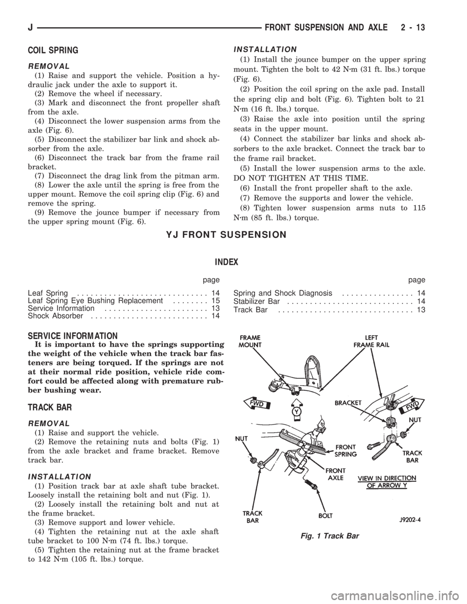
COIL SPRING
REMOVAL
(1) Raise and support the vehicle. Position a hy-
draulic jack under the axle to support it.
(2) Remove the wheel if necessary.
(3) Mark and disconnect the front propeller shaft
from the axle.
(4) Disconnect the lower suspension arms from the
axle (Fig. 6).
(5) Disconnect the stabilizer bar link and shock ab-
sorber from the axle.
(6) Disconnect the track bar from the frame rail
bracket.
(7) Disconnect the drag link from the pitman arm.
(8) Lower the axle until the spring is free from the
upper mount. Remove the coil spring clip (Fig. 6) and
remove the spring.
(9) Remove the jounce bumper if necessary from
the upper spring mount (Fig. 6).
INSTALLATION
(1) Install the jounce bumper on the upper spring
mount. Tighten the bolt to 42 Nzm (31 ft. lbs.) torque
(Fig. 6).
(2) Position the coil spring on the axle pad. Install
the spring clip and bolt (Fig. 6). Tighten bolt to 21
Nzm (16 ft. lbs.) torque.
(3) Raise the axle into position until the spring
seats in the upper mount.
(4) Connect the stabilizer bar links and shock ab-
sorbers to the axle bracket. Connect the track bar to
the frame rail bracket.
(5) Install the lower suspension arms to the axle.
DO NOT TIGHTEN AT THIS TIME.
(6) Install the front propeller shaft to the axle.
(7) Remove the supports and lower the vehicle.
(8) Tighten lower suspension arms nuts to 115
Nzm (85 ft. lbs.) torque.
YJ FRONT SUSPENSION
INDEX
page page
Leaf Spring............................. 14
Leaf Spring Eye Bushing Replacement........ 15
Service Information....................... 13
Shock Absorber.......................... 14Spring and Shock Diagnosis................ 14
Stabilizer Bar............................ 14
Track Bar.............................. 13
SERVICE INFORMATION
It is important to have the springs supporting
the weight of the vehicle when the track bar fas-
teners are being torqued. If the springs are not
at their normal ride position, vehicle ride com-
fort could be affected along with premature rub-
ber bushing wear.
TRACK BAR
REMOVAL
(1) Raise and support the vehicle.
(2) Remove the retaining nuts and bolts (Fig. 1)
from the axle bracket and frame bracket. Remove
track bar.
INSTALLATION
(1) Position track bar at axle shaft tube bracket.
Loosely install the retaining bolt and nut (Fig. 1).
(2) Loosely install the retaining bolt and nut at
the frame bracket.
(3) Remove support and lower vehicle.
(4) Tighten the retaining nut at the axle shaft
tube bracket to 100 Nzm (74 ft. lbs.) torque.
(5) Tighten the retaining nut at the frame bracket
to 142 Nzm (105 ft. lbs.) torque.
Fig. 1 Track Bar
JFRONT SUSPENSION AND AXLE 2 - 13
Page 54 of 1784
level. Where axle bearing damage is slight, the noise
is usually not noticeable at speeds above 30 mph.
LOW SPEED KNOCK
Low speed knock is generally caused by a worn
U-joint or by worn side-gear thrust washers. A worn
pinion gear shaft bore will also cause low speed
knock.
VIBRATION
Vibration at the rear of the vehicle is usually
caused by a:
²Damaged drive shaft
²Missing drive shaft balance weight
²Worn, out-of-balance wheels
²Loose wheel lug nuts
²Worn U-joint
²Loose spring U-bolts
²Loose/broken springs
²Damaged axle shaft bearings
²Loose pinion gear nut
²Excessive pinion yoke run out
²Bent axle shaft
Check for loose or damaged front-end components
or engine/transmission mounts. These componentscan contribute to what appears to be a rear-end vi-
bration. Do not overlook engine accessories, brackets
and drive belts.
All driveline components should be examined be-
fore starting any repair.
Refer to Group 22ÐTires And Wheels for addi-
tional information involving vibration diagnosis.
DRIVELINE SNAP
A snap or clunk noise when the vehicle is shifted
into gear (or the clutch engaged), can be caused by:
²High engine idle speed
²Loose engine/transmission/transfer case mounts
²Worn U-joints
²Loose spring mounts
²Loose pinion gear nut and yoke
²Excessive ring gear backlash
²Excessive differential side gear-to-case clearance
The source of a snap or a clunk noise can be deter-
mined with the assistance of a helper. Raise the ve-
hicle on a hoist with the wheels free to rotate.
Instruct the helper to shift the transmission into
gear. Listen for the noise, a mechanics stethoscope is
helpful in isolating the source of a noise.
JFRONT SUSPENSION AND AXLE 2 - 17
Page 58 of 1784
Refer to Group 0, Lubrication and Maintenance for
additional information regarding temperature range,
viscosity and fluid level.
CAUTION: If the axle is submerged in water, the lu-
bricant must be replaced immediately to avoid the
possibility of premature axle failure.
DRIVE AXLE ASSEMBLY REPLACEMENTÐXJ
VEHICLES
REMOVAL
(1) Raise the vehicle and position support stands
under the frame rails slightly in behind the lower
suspension arm frame brackets.
(2) Remove the front wheels.
(3) Remove the brake components and ABS brake
sensor (if equipped). Refer to Group 5ÐBrakes.
(4) On 4WD vehicles, disconnect the axle vent
hose.
(5) On 4WD vehicles, mark the drive shaft yoke
and axle pinion yoke for alignment reference. Discon-
nect the drive shaft from the axle.
(6) Disconnect the stabilizer bar link at the axle
bracket.
(7) Disconnect the shock absorbers from axle
bracket.
(8) Disconnect the track bar from the axle bracket.
(9) Disconnect the tie rod and drag link from the
steering knuckle. Disconnect the steering dampener
from the axle bracket.
(10) Support the axle with a hydraulic jack under
the differential.
(11) Disconnect the upper and lower suspension
arms from the axle bracket.
(12) Lower the jack enough to remove the axle.
The coil springs will drop with the axle.
(13) Remove the coil springs from the axle bracket.
INSTALLATION
CAUTION: All suspension components that use rub-
ber bushings should be tightened with the vehicle
at the ride height. It is important to have the
springs supporting the weight of the vehicle when
the fasteners are torqued. If the springs are not at
their normal ride position, vehicle ride comfort
could be affected along with premature rubber
bushing wear. Rubber bushings must never be lu-
bricated.
(1) Install the springs and retainer clip. Tighten
the retainer bolts to 21 Nzm (16 ft. lbs.) torque.
(2) Support the axle on a hydraulic jack under the
differential. Position the axle under the vehicle.
(3) Raise the axle with a floor jack and align it
with the spring pads.(4) Position the upper and lower suspension arm at
the axle bracket. Install bolts and nuts finger
tighten.
(5) Connect the track bar to the axle bracket and
install the bolt.Do not tighten at this time.
It is important that the springs support the
weight of the vehicle when the track bar is con-
nected. If the springs are not at their usual po-
sition, the vehicle ride comfort could be affected.
(6) Install the shock absorber and tighten the bolt
to 19 Nzm (14 ft. lbs.) torque.
(7) Install the stabilizer bar link to the axle
bracket. Tighten the nut to 95 Nzm (70 ft. lbs.)
torque.
(8) Install the drag link and tie rod to the steering
knuckles and tighten the nuts to 47 Nzm (35 ft. lbs.)
torque. Install the steering dampener to the axle
bracket and tighten the nut to 75 Nzm (55 ft. lbs.)
torque.
(9) Install the brake components and ABS brake
sensor (if equipped). Refer to Group 5ÐBrakes.
(10) On 4WD vehicles, connect the vent hose to the
tube fitting.
(11) On 4WD vehicles, align the reference marks
and connect the drive shaft to the axle yoke. Tighten
the U-joint clamp bolts to 19 Nzm (14 ft. lbs.) torque.
(12) Check differential lubricant and add if neces-
sary.
(13) Install the wheel and tire assemblies.
(14) Remove the supports and lower the vehicle.
(15) Tighten the upper suspension arm nuts to 75
Nzm (55 ft. lbs.) torque. Tighten the lower suspension
arm nuts to 115 Nzm (85 ft. lbs.) torque.
(16) Tighten the track bar bolt at the axle bracket
to 100 Nzm (74 ft. lbs.) torque.
(17) Check the front wheel alignment.
DRIVE AXLE ASSEMBLY REPLACEMENTÐYJ
VEHICLES
REMOVAL
(1) Raise the vehicle and position support stands
under the frame rails slightly behind the spring
frame brackets.
(2) Remove the front wheels.
(3) Remove the brake components and ABS brake
sensor (if equipped). Refer to Group 5ÐBrakes.
(4) Disconnect the axle vent hose and axle shift
motor vacuum harness.
(5) Mark the drive shaft yoke and axle pinion yoke
for alignment reference. Disconnect the drive shaft
from the axle.
(6) Disconnect the stabilizer bar link at the axle
bracket.
(7) Disconnect the shock absorbers from axle
bracket.
(8) Disconnect the track bar from the axle bracket.
JFRONT SUSPENSION AND AXLE 2 - 21