1994 JEEP CHEROKEE ground clearance
[x] Cancel search: ground clearancePage 261 of 1784
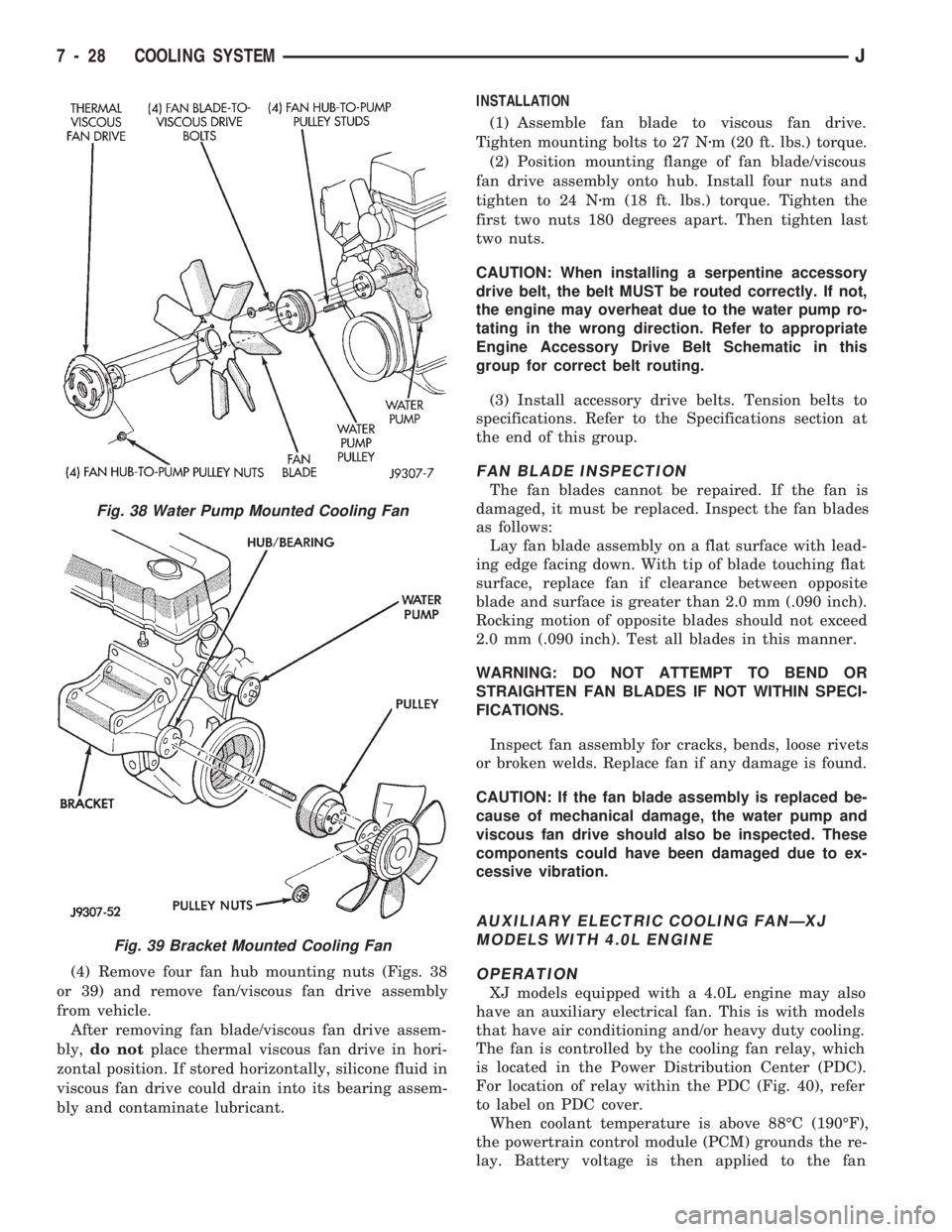
(4) Remove four fan hub mounting nuts (Figs. 38
or 39) and remove fan/viscous fan drive assembly
from vehicle.
After removing fan blade/viscous fan drive assem-
bly,do notplace thermal viscous fan drive in hori-
zontal position. If stored horizontally, silicone fluid in
viscous fan drive could drain into its bearing assem-
bly and contaminate lubricant.INSTALLATION
(1) Assemble fan blade to viscous fan drive.
Tighten mounting bolts to 27 Nzm (20 ft. lbs.) torque.
(2) Position mounting flange of fan blade/viscous
fan drive assembly onto hub. Install four nuts and
tighten to 24 Nzm (18 ft. lbs.) torque. Tighten the
first two nuts 180 degrees apart. Then tighten last
two nuts.
CAUTION: When installing a serpentine accessory
drive belt, the belt MUST be routed correctly. If not,
the engine may overheat due to the water pump ro-
tating in the wrong direction. Refer to appropriate
Engine Accessory Drive Belt Schematic in this
group for correct belt routing.
(3) Install accessory drive belts. Tension belts to
specifications. Refer to the Specifications section at
the end of this group.
FAN BLADE INSPECTION
The fan blades cannot be repaired. If the fan is
damaged, it must be replaced. Inspect the fan blades
as follows:
Lay fan blade assembly on a flat surface with lead-
ing edge facing down. With tip of blade touching flat
surface, replace fan if clearance between opposite
blade and surface is greater than 2.0 mm (.090 inch).
Rocking motion of opposite blades should not exceed
2.0 mm (.090 inch). Test all blades in this manner.
WARNING: DO NOT ATTEMPT TO BEND OR
STRAIGHTEN FAN BLADES IF NOT WITHIN SPECI-
FICATIONS.
Inspect fan assembly for cracks, bends, loose rivets
or broken welds. Replace fan if any damage is found.
CAUTION: If the fan blade assembly is replaced be-
cause of mechanical damage, the water pump and
viscous fan drive should also be inspected. These
components could have been damaged due to ex-
cessive vibration.
AUXILIARY ELECTRIC COOLING FANÐXJ
MODELS WITH 4.0L ENGINE
OPERATION
XJ models equipped with a 4.0L engine may also
have an auxiliary electrical fan. This is with models
that have air conditioning and/or heavy duty cooling.
The fan is controlled by the cooling fan relay, which
is located in the Power Distribution Center (PDC).
For location of relay within the PDC (Fig. 40), refer
to label on PDC cover.
When coolant temperature is above 88ÉC (190ÉF),
the powertrain control module (PCM) grounds the re-
lay. Battery voltage is then applied to the fan
Fig. 38 Water Pump Mounted Cooling Fan
Fig. 39 Bracket Mounted Cooling Fan
7 - 28 COOLING SYSTEMJ
Page 864 of 1784
INSPECTION
Inspect for cracks in the combustion chambers and
valve ports.
Inspect for cracks on the exhaust seat.
Inspect for cracks in the gasket surface at each
coolant passage.
Inspect valves for burned, cracked or warped heads.
Inspect for scuffed or bent valve stems.
Replace valves displaying any damage.
VALVE REFACING
(1) Use a valve refacing machine to reface the in-
take and exhaust valves to the specified angle.
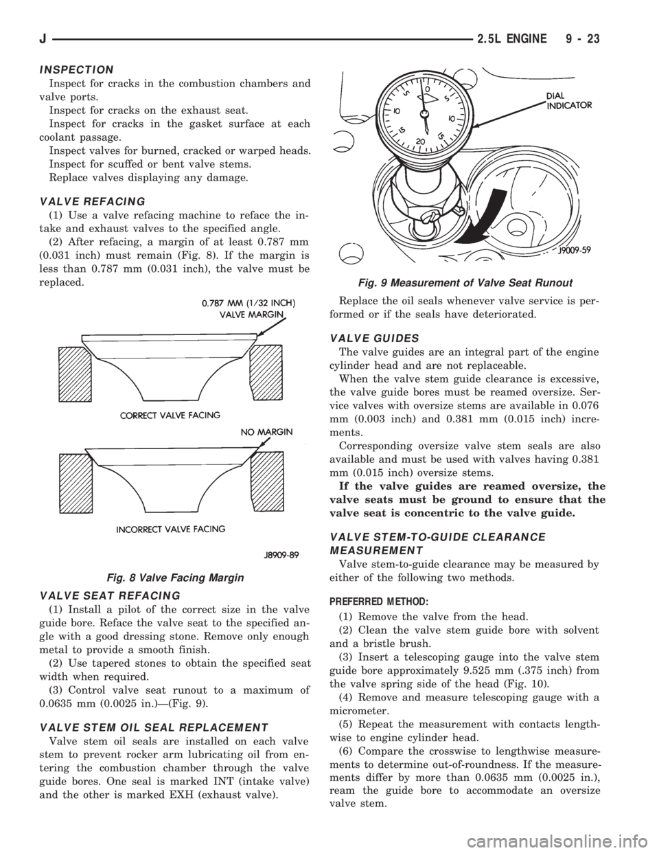
(2) After refacing, a margin of at least 0.787 mm
(0.031 inch) must remain (Fig. 8). If the margin is
less than 0.787 mm (0.031 inch), the valve must be
replaced.
VALVE SEAT REFACING
(1) Install a pilot of the correct size in the valve
guide bore. Reface the valve seat to the specified an-
gle with a good dressing stone. Remove only enough
metal to provide a smooth finish.
(2) Use tapered stones to obtain the specified seat
width when required.
(3) Control valve seat runout to a maximum of
0.0635 mm (0.0025 in.)Ð(Fig. 9).
VALVE STEM OIL SEAL REPLACEMENT
Valve stem oil seals are installed on each valve
stem to prevent rocker arm lubricating oil from en-
tering the combustion chamber through the valve
guide bores. One seal is marked INT (intake valve)
and the other is marked EXH (exhaust valve).Replace the oil seals whenever valve service is per-
formed or if the seals have deteriorated.
VALVE GUIDES
The valve guides are an integral part of the engine
cylinder head and are not replaceable.
When the valve stem guide clearance is excessive,
the valve guide bores must be reamed oversize. Ser-
vice valves with oversize stems are available in 0.076
mm (0.003 inch) and 0.381 mm (0.015 inch) incre-
ments.
Corresponding oversize valve stem seals are also
available and must be used with valves having 0.381
mm (0.015 inch) oversize stems.
If the valve guides are reamed oversize, the
valve seats must be ground to ensure that the
valve seat is concentric to the valve guide.
VALVE STEM-TO-GUIDE CLEARANCE
MEASUREMENT
Valve stem-to-guide clearance may be measured by
either of the following two methods.
PREFERRED METHOD:
(1) Remove the valve from the head.
(2) Clean the valve stem guide bore with solvent
and a bristle brush.
(3) Insert a telescoping gauge into the valve stem
guide bore approximately 9.525 mm (.375 inch) from
the valve spring side of the head (Fig. 10).
(4) Remove and measure telescoping gauge with a
micrometer.
(5) Repeat the measurement with contacts length-
wise to engine cylinder head.
(6) Compare the crosswise to lengthwise measure-
ments to determine out-of-roundness. If the measure-
ments differ by more than 0.0635 mm (0.0025 in.),
ream the guide bore to accommodate an oversize
valve stem.
Fig. 8 Valve Facing Margin
Fig. 9 Measurement of Valve Seat Runout
J2.5L ENGINE 9 - 23
Page 865 of 1784
(7) Compare the measured valve guide bore diam-
eter with specifications (7.95-7.97 mm or 0.313-0.314
inch). If the measurement differs from specification
by more than 0.076 mm (0.003 inch), ream the guide
bore to accommodate an oversize valve stem.
ALTERNATIVE METHOD:
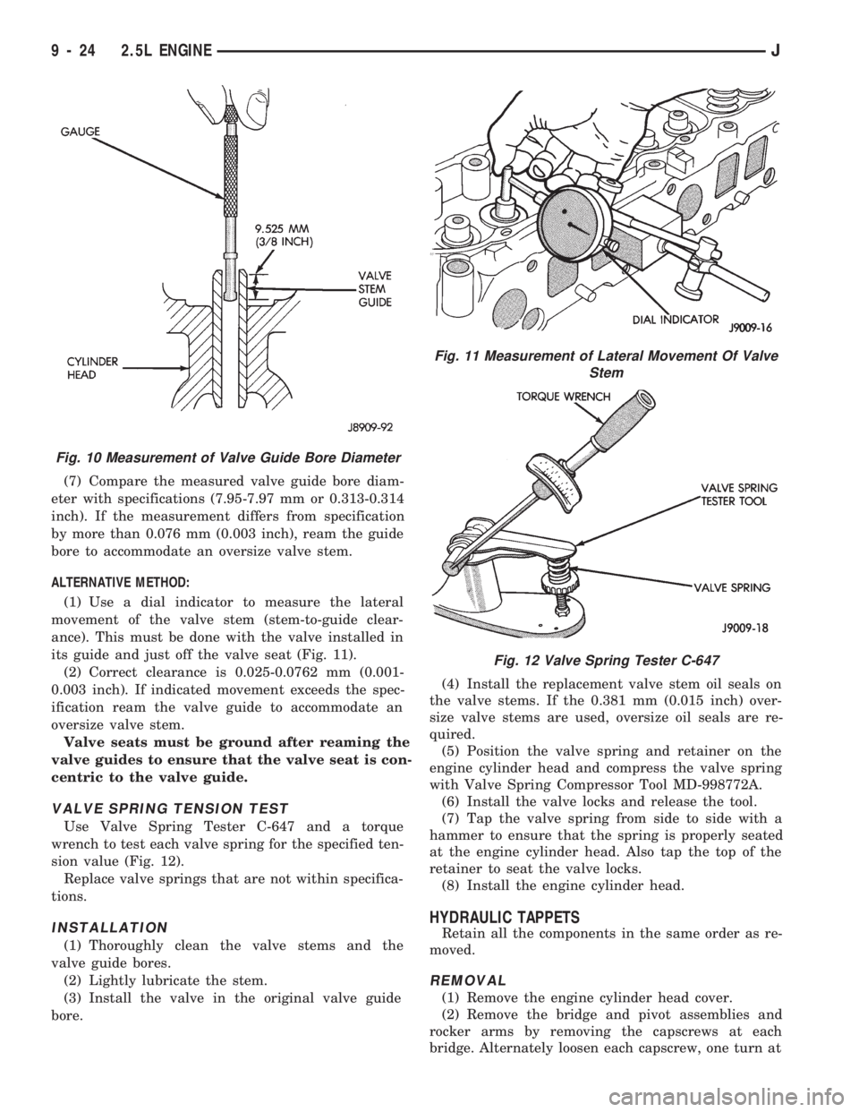
(1) Use a dial indicator to measure the lateral
movement of the valve stem (stem-to-guide clear-
ance). This must be done with the valve installed in
its guide and just off the valve seat (Fig. 11).
(2) Correct clearance is 0.025-0.0762 mm (0.001-
0.003 inch). If indicated movement exceeds the spec-
ification ream the valve guide to accommodate an
oversize valve stem.
Valve seats must be ground after reaming the
valve guides to ensure that the valve seat is con-
centric to the valve guide.
VALVE SPRING TENSION TEST
Use Valve Spring Tester C-647 and a torque
wrench to test each valve spring for the specified ten-
sion value (Fig. 12).
Replace valve springs that are not within specifica-
tions.
INSTALLATION
(1) Thoroughly clean the valve stems and the
valve guide bores.
(2) Lightly lubricate the stem.
(3) Install the valve in the original valve guide
bore.(4) Install the replacement valve stem oil seals on
the valve stems. If the 0.381 mm (0.015 inch) over-
size valve stems are used, oversize oil seals are re-
quired.
(5) Position the valve spring and retainer on the
engine cylinder head and compress the valve spring
with Valve Spring Compressor Tool MD-998772A.
(6) Install the valve locks and release the tool.
(7) Tap the valve spring from side to side with a
hammer to ensure that the spring is properly seated
at the engine cylinder head. Also tap the top of the
retainer to seat the valve locks.
(8) Install the engine cylinder head.
HYDRAULIC TAPPETS
Retain all the components in the same order as re-
moved.
REMOVAL
(1) Remove the engine cylinder head cover.
(2) Remove the bridge and pivot assemblies and
rocker arms by removing the capscrews at each
bridge. Alternately loosen each capscrew, one turn at
Fig. 10 Measurement of Valve Guide Bore Diameter
Fig. 11 Measurement of Lateral Movement Of Valve
Stem
Fig. 12 Valve Spring Tester C-647
9 - 24 2.5L ENGINEJ
Page 878 of 1784

SIDE CLEARANCE MEASUREMENT
Slide snug-fitting feeler gauge between the con-
necting rod and crankshaft journal flange. Refer to
Engine Specifications for the proper clearance. Re-
place the connecting rod if the side clearance is not
within specification.
PISTON FITTING
MICROMETER METHOD
(1) Measure the inside diameter of the cylinder
bore at a point 58.725 mm (2-5/16 inches) below top
of bore.
(2) Measure outside diameter of the piston. Be-
cause pistons are cam ground, measure at right an-
gle to piston pin at center line of pin (Fig. 8).
The difference between cylinder bore diameter and
piston diameter is piston-to-bore clearance.
FEELER GAUGE METHOD
(1) Remove the rings from the piston.
(2) Insert a long 0.025 mm (0.001 inch) feeler
gauge into the cylinder bore.
(3) Insert the piston, top first, into cylinder bore
alongside the feeler gauge. With entire piston in-
serted into cylinder bore, the piston should not bind
against feeler gauge.
(4) Repeat steps with a long 0.051 mm (0.002 inch)
feeler gauge. The piston should bind.
(5) If the piston binds on 0.025 mm (0.001 inch)
feeler gauge, the piston is too large or cylinder bore
is too small. If the piston does not bind on 0.051 mm
(0.002 inch) feeler gauge, the piston is too small for
cylinder bore. Pistons up to 0.102 mm (0.004 inch)undersize may be enlarged by knurling or shot-peen-
ing. Replace pistons that are 0.102 mm (0.004 inch)
or more undersize.
PISTON PIN
REMOVAL
Piston pins are press-fitted into the connecting rods
and require no locking device.
(1) Position the piston and connecting rod assem-
bly on an arbor press.
(2) Apply force to a piloted driver and press the
pin completely out of the connecting rod and piston
assembly (Fig. 9). Note position of the pin through
the gauge window of removal support tool.
INSPECTION
(1) Inspect the piston pin and pin bore in the con-
necting rod for nicks and burrs. Remove as neces-
sary. Never reuse a piston pin after it has been
installed in and removed from a connecting rod.
(2) With the pin removed from the piston and con-
necting rod, clean and dry piston pin bores and the
replacement piston pin.
(3) Position the piston so that the pin bore is in
vertical position. Insert the pin in bore. At room tem-
perature, the replacement pin should slide com-
pletely through the pin bore in piston by force of
gravity.
(4) Replace piston if pin jams in the pin bore.
INSTALLATION
(1) Insert the piston pin pilot through the piston
and connecting rod pin bores. Ensure that the arrow
on the piston crown is pointing up (Fig. 10).
Fig. 8 Piston Dimensions
Fig. 9 Piston Pin Removal/Installation
J2.5L ENGINE 9 - 37
Page 905 of 1784
gle with a good dressing stone. Remove only enough
metal to provide a smooth finish.
(2) Use tapered stones to obtain the specified seat
width when required.
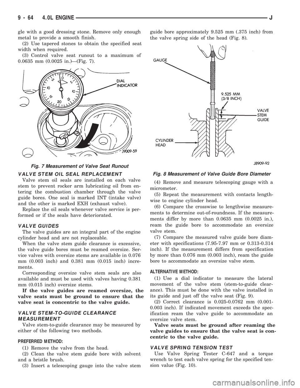
(3) Control valve seat runout to a maximum of
0.0635 mm (0.0025 in.)Ð(Fig. 7).
VALVE STEM OIL SEAL REPLACEMENT
Valve stem oil seals are installed on each valve
stem to prevent rocker arm lubricating oil from en-
tering the combustion chamber through the valve
guide bores. One seal is marked INT (intake valve)
and the other is marked EXH (exhaust valve).
Replace the oil seals whenever valve service is per-
formed or if the seals have deteriorated.
VALVE GUIDES
The valve guides are an integral part of the engine
cylinder head and are not replaceable.
When the valve stem guide clearance is excessive,
the valve guide bores must be reamed oversize. Ser-
vice valves with oversize stems are available in 0.076
mm (0.003 inch) and 0.381 mm (0.015 inch) incre-
ments.
Corresponding oversize valve stem seals are also
available and must be used with valves having 0.381
mm (0.015 inch) oversize stems.
If the valve guides are reamed oversize, the
valve seats must be ground to ensure that the
valve seat is concentric to the valve guide.
VALVE STEM-TO-GUIDE CLEARANCE
MEASUREMENT
Valve stem-to-guide clearance may be measured by
either of the following two methods.
PREFERRED METHOD:
(1) Remove the valve from the head.
(2) Clean the valve stem guide bore with solvent
and a bristle brush.
(3) Insert a telescoping gauge into the valve stemguide bore approximately 9.525 mm (.375 inch) from
the valve spring side of the head (Fig. 8).
(4) Remove and measure telescoping gauge with a
micrometer.
(5) Repeat the measurement with contacts length-
wise to engine cylinder head.
(6) Compare the crosswise to lengthwise measure-
ments to determine out-of-roundness. If the measure-
ments differ by more than 0.0635 mm (0.0025 in.),
ream the guide bore to accommodate an oversize
valve stem.
(7) Compare the measured valve guide bore diam-
eter with specifications (7.95-7.97 mm or 0.313-0.314
inch). If the measurement differs from specification
by more than 0.076 mm (0.003 inch), ream the guide
bore to accommodate an oversize valve stem.
ALTERNATIVE METHOD:
(1) Use a dial indicator to measure the lateral
movement of the valve stem (stem-to-guide clear-
ance). This must be done with the valve installed in
its guide and just off the valve seat (Fig. 9).
(2) Correct clearance is 0.025-0.0762 mm (0.001-
0.003 inch). If indicated movement exceeds the spec-
ification ream the valve guide to accommodate an
oversize valve stem.
Valve seats must be ground after reaming the
valve guides to ensure that the valve seat is con-
centric to the valve guide.
VALVE SPRING TENSION TEST
Use Valve Spring Tester C-647 and a torque
wrench to test each valve spring for the specified ten-
sion value (Fig. 10).
Fig. 7 Measurement of Valve Seat Runout
Fig. 8 Measurement of Valve Guide Bore Diameter
9 - 64 4.0L ENGINEJ
Page 917 of 1784
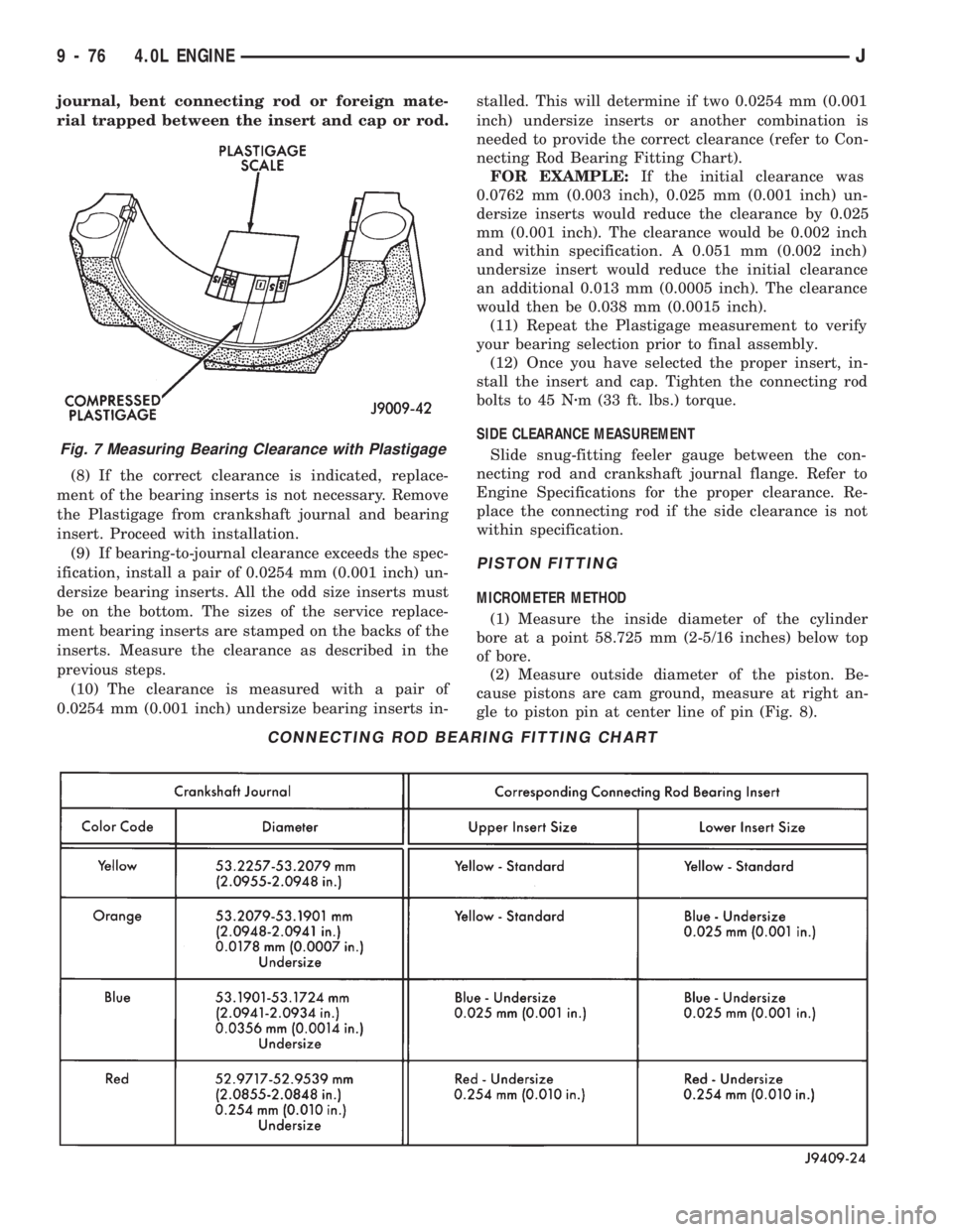
journal, bent connecting rod or foreign mate-
rial trapped between the insert and cap or rod.
(8) If the correct clearance is indicated, replace-
ment of the bearing inserts is not necessary. Remove
the Plastigage from crankshaft journal and bearing
insert. Proceed with installation.
(9) If bearing-to-journal clearance exceeds the spec-
ification, install a pair of 0.0254 mm (0.001 inch) un-
dersize bearing inserts. All the odd size inserts must
be on the bottom. The sizes of the service replace-
ment bearing inserts are stamped on the backs of the
inserts. Measure the clearance as described in the
previous steps.
(10) The clearance is measured with a pair of
0.0254 mm (0.001 inch) undersize bearing inserts in-stalled. This will determine if two 0.0254 mm (0.001
inch) undersize inserts or another combination is
needed to provide the correct clearance (refer to Con-
necting Rod Bearing Fitting Chart).
FOR EXAMPLE:If the initial clearance was
0.0762 mm (0.003 inch), 0.025 mm (0.001 inch) un-
dersize inserts would reduce the clearance by 0.025
mm (0.001 inch). The clearance would be 0.002 inch
and within specification. A 0.051 mm (0.002 inch)
undersize insert would reduce the initial clearance
an additional 0.013 mm (0.0005 inch). The clearance
would then be 0.038 mm (0.0015 inch).
(11) Repeat the Plastigage measurement to verify
your bearing selection prior to final assembly.
(12) Once you have selected the proper insert, in-
stall the insert and cap. Tighten the connecting rod
bolts to 45 Nzm (33 ft. lbs.) torque.
SIDE CLEARANCE MEASUREMENT
Slide snug-fitting feeler gauge between the con-
necting rod and crankshaft journal flange. Refer to
Engine Specifications for the proper clearance. Re-
place the connecting rod if the side clearance is not
within specification.
PISTON FITTING
MICROMETER METHOD
(1) Measure the inside diameter of the cylinder
bore at a point 58.725 mm (2-5/16 inches) below top
of bore.
(2) Measure outside diameter of the piston. Be-
cause pistons are cam ground, measure at right an-
gle to piston pin at center line of pin (Fig. 8).
CONNECTING ROD BEARING FITTING CHART
Fig. 7 Measuring Bearing Clearance with Plastigage
9 - 76 4.0L ENGINEJ
Page 1549 of 1784
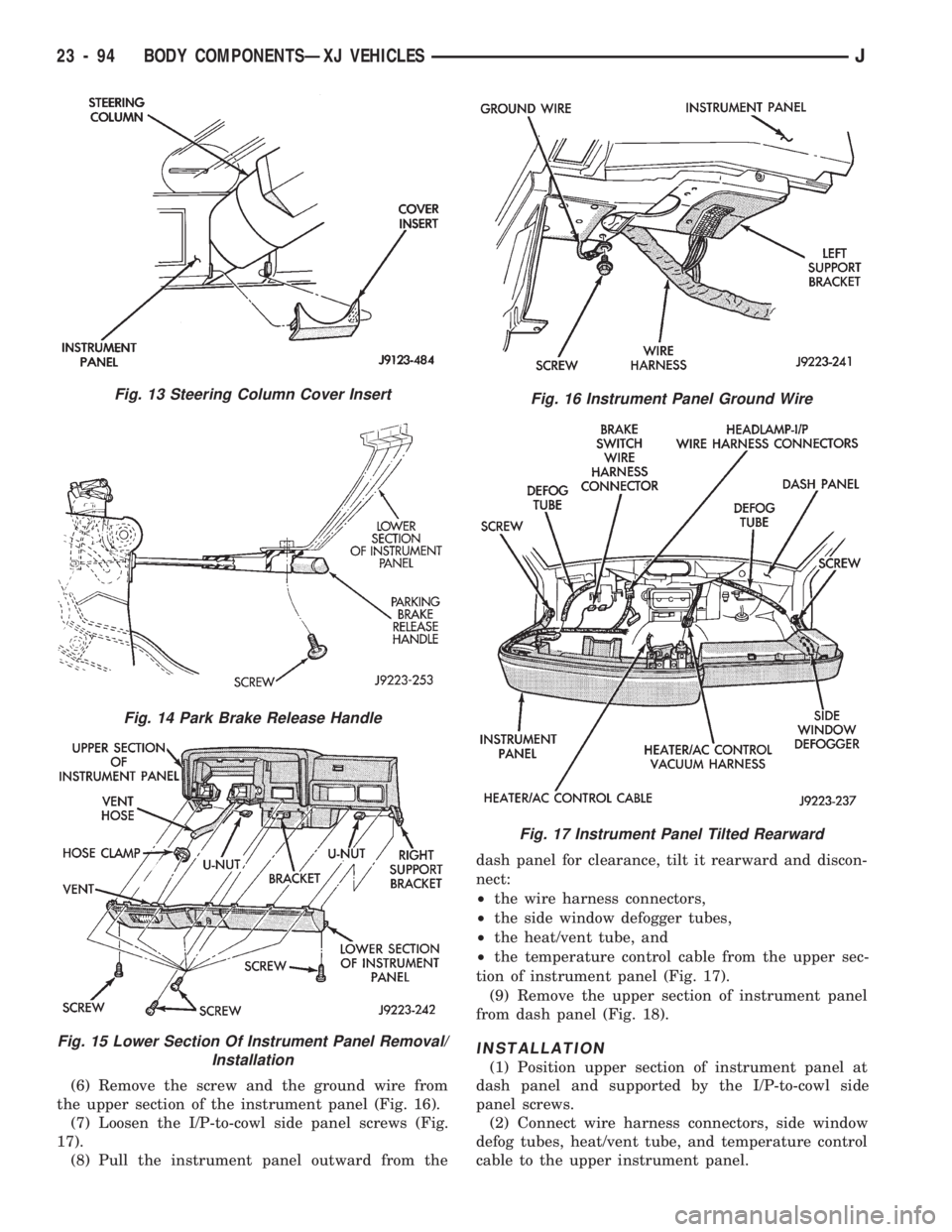
(6) Remove the screw and the ground wire from
the upper section of the instrument panel (Fig. 16).
(7) Loosen the I/P-to-cowl side panel screws (Fig.
17).
(8) Pull the instrument panel outward from thedash panel for clearance, tilt it rearward and discon-
nect:
²the wire harness connectors,
²the side window defogger tubes,
²the heat/vent tube, and
²the temperature control cable from the upper sec-
tion of instrument panel (Fig. 17).
(9) Remove the upper section of instrument panel
from dash panel (Fig. 18).
INSTALLATION
(1) Position upper section of instrument panel at
dash panel and supported by the I/P-to-cowl side
panel screws.
(2) Connect wire harness connectors, side window
defog tubes, heat/vent tube, and temperature control
cable to the upper instrument panel.
Fig. 13 Steering Column Cover Insert
Fig. 14 Park Brake Release Handle
Fig. 15 Lower Section Of Instrument Panel Removal/
Installation
Fig. 16 Instrument Panel Ground Wire
Fig. 17 Instrument Panel Tilted Rearward
23 - 94 BODY COMPONENTSÐXJ VEHICLESJ