1994 JEEP CHEROKEE diagram
[x] Cancel search: diagramPage 123 of 1784
(29) Verify that fuel pump module wire connector
is firmly connected to harness connector.
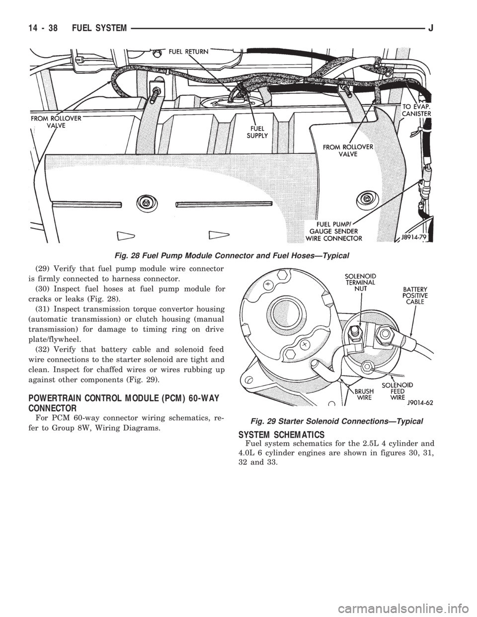
(30) Inspect fuel hoses at fuel pump module for
cracks or leaks (Fig. 28).
(31) Inspect transmission torque convertor housing
(automatic transmission) or clutch housing (manual
transmission) for damage to timing ring on drive
plate/flywheel.
(32) Verify that battery cable and solenoid feed
wire connections to the starter solenoid are tight and
clean. Inspect for chaffed wires or wires rubbing up
against other components (Fig. 29).
POWERTRAIN CONTROL MODULE (PCM) 60-WAY
CONNECTOR
For PCM 60-way connector wiring schematics, re-
fer to Group 8W, Wiring Diagrams.
SYSTEM SCHEMATICS
Fuel system schematics for the 2.5L 4 cylinder and
4.0L 6 cylinder engines are shown in figures 30, 31,
32 and 33.
Fig. 28 Fuel Pump Module Connector and Fuel HosesÐTypical
Fig. 29 Starter Solenoid ConnectionsÐTypical
14 - 38 FUEL SYSTEMJ
Page 130 of 1784
EXTENDED IDLE SWITCH TEST
OPTIONAL POLICE PACKAGE ONLY
OPERATION
The extended idle switch is used to raise the en-
gine idle speed to approximately 1000 rpm when the
shifter is in either the Park or Neutral position. A
rocker-type 2-wire switch (extended idle switch) is
mounted to the instrument panel.This switch is
available only with 4.0L engine when supplied
with the optional police package.
TESTING
The extended idle switch will control a ground cir-
cuit going to the powertrain control module (PCM).
When a ground signal (through this switch) has been
received at pin number 10 in the PCM, engine idle
speed will increase.
Bring the engine to normal operating temperature
and turn the extended idle switch to the ON position.
Engine speed should now increase to approximately
1000 rpm when the shifter is in either the Park or
Neutral position. If engine speed does not increase,
apply a good ground to pin number 10 at the PCM
using a small paper clip. Be careful not to damage
the wiring with the paper clip. If the engine speed
now increases, it can be assumed that the PCM is
functioning correctly. Check the instrument panel
mounted switch for a closed ground circuit when in
the ON position. If the engine speed will not increase
after applying a ground to pin number 10, replace
the PCM. Refer to Group 8W, Wiring Diagrams for
circuit and wiring information.
THROTTLE POSITION SENSOR (TPS) TEST
To perform a complete test of the sensor and its cir-
cuitry, refer to DRB scan tool and appropriate Pow-
ertrain Diagnostics Procedures manual. To test the
sensor only, refer to the following:
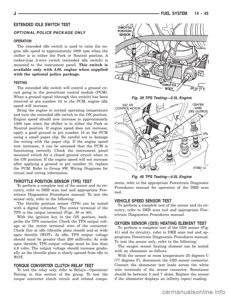
The throttle position sensor (TPS) can be tested
with a digital voltmeter. The center terminal of the
TPS is the output terminal (Figs. 39 or 40).
With the ignition key in the ON position, back-
probe the TPS connector. Check the TPS output volt-
age at the center terminal wire of the connector.
Check this at idle (throttle plate closed) and at wide
open throttle (WOT). At idle, TPS output voltage
should must be greater than 200 millivolts. At wide
open throttle, TPS output voltage must be less than
4.8 volts. The output voltage should increase gradu-
ally as the throttle plate is slowly opened from idle to
WOT.
TORQUE CONVERTER CLUTCH RELAY TEST
To test the relay only, refer to RelaysÐOperation/
Testing in this section of the group. To test the
torque converter clutch circuit and related compo-nents, refer to the appropriate Powertrain Diagnostic
Procedures manual for operation of the DRB scan
tool.
VEHICLE SPEED SENSOR TEST
To perform a complete test of the sensor and its cir-
cuitry, refer to DRB scan tool and appropriate Pow-
ertrain Diagnostics Procedures manual.
OXYGEN SENSOR (O2S) HEATING ELEMENT TEST
To perform a complete test of the O2S sensor (Fig.
41) and its circuitry, refer to DRB scan tool and ap-
propriate Powertrain Diagnostics Procedures manual.
To test the sensor only, refer to the following:
The oxygen sensor heating element can be tested
with an ohmmeter as follows:
With the sensor at room temperature 25 degrees C
(77 degrees F), disconnect the O2S sensor connector.
Connect the ohmmeter test leads across the white
wire terminals of the sensor connector. Resistance
should be between 5 and 7 ohms. Replace the sensor
if the ohmmeter displays an infinity (open) reading.
Fig. 39 TPS TestingÐ2.5L Engine
Fig. 40 TPS TestingÐ4.0L Engine
JFUEL SYSTEM 14 - 45
Page 133 of 1784

87 and 30. Continuity should not be present between
terminals number 87A and 30.
(8) Disconnect jumper wires from relay and 12
Volt power source.
If continuity or resistance tests did not pass, re-
place relay. If tests passed, refer to Group 8W, Wir-
ing Diagrams for additional circuit information. Also
refer to the appropriate Powertrain Diagnostic Proce-
dures manual for operation of the DRB scan tool.
STARTER MOTOR RELAY TEST
Refer to Group 8A, Battery/Starting/Charging/Sys-
tem Diagnostics, for starter motor relay testing.
INJECTOR TEST
Disconnect the injector wire connector from the in-
jector. Place an ohmmeter on the injector terminals.
Resistance reading should be approximately 14.5
ohms61.2 ohms at 20ÉC (68ÉF). Proceed to following
Injector Diagnosis chart.
FUEL SYSTEM PRESSURE TEST
Refer to the Fuel Delivery System section of this
group. See Fuel System Pressure Test.
ON-BOARD DIAGNOSTICS (OBD)
The Powertrain Control Module (PCM) has been
programmed to monitor many different circuits of the
fuel injection system. If a problem is sensed in a
monitored circuit often enough to indicate an actual
problem, a Diagnostic Trouble Code (DTC) is stored.
The DTC will be stored in the PCM memory for
eventual display to the service technician. If the
problem is repaired or ceases to exist, the PCM can-
cels the DTC after 51 engine starts.
Certain criteria must be met for a diagnostic trou-
ble code (DTC) to be entered into PCM memory. The
criteria may be a specific range of engine rpm, en-
gine temperature and/or input voltage to the PCM.
It is possible that a DTC for a monitored circuit
may not be entered into memory even though a mal-
function has occurred. This may happen because one
of the DTC criteria for the circuit has not been met.
Example: assume that one of the criteria for the
MAP sensor circuit is that the engine must be oper-
ating between 750 and 2000 rpm to be monitored for
a DTC. If the MAP sensor output circuit shorts to
ground when the engine rpm is above 2400 rpm, a 0
volt input will be seen by the PCM. A DTC will not
be entered into memory because the condition does
not occur within the specified rpm range.
A DTC indicates that the powertrain control mod-
ule (PCM) has recognized an abnormal signal in a
circuit or the system. A DTC may indicate the result
of a failure, but never identify the failed component
directly.There are several operating conditions that the
PCM does not monitor and set a DTC for. Refer to
the following Monitored Circuits and Non-Monitored
Circuits in this section.
MONITORED CIRCUITS
The powertrain control module (PCM) can detect
certain problems in the fuel injection system.
Open or Shorted Circuit- The PCM can deter-
mine if sensor output (which is the input to PCM) is
within proper range. It also determines if the circuit
is open or shorted.
Output Device Current Flow- The PCM senses
whether the output devices are hooked up.
If there is a problem with the circuit, the PCM
senses whether the circuit is open, shorted to ground
(-), or shorted to (+) voltage.
Oxygen Sensor- The PCM can determine if the
oxygen sensor is switching between rich and lean.
This is, once the system has entered Closed Loop. Re-
fer to Open Loop/Closed Loop Modes Of Operation in
the Component Description/System Operation section
for an explanation of Closed (or Open) Loop opera-
tion.
NON-MONITORED CIRCUITS
The PCM does not monitor the following circuits,
systems or conditions that could have malfunctions
that result in driveability problems. A Diagnostic
Trouble Code (DTC) may not be displayed for these
conditions.
Fuel Pressure: Fuel pressure is controlled by the
vacuum assisted fuel pressure regulator. The PCM
cannot detect a clogged fuel pump inlet filter, clogged
in-line fuel filter, or a pinched fuel supply or return
line. However, these could result in a rich or lean
condition causing an oxygen sensor DTC to be stored
in the PCM.
Secondary Ignition Circuit: The PCM cannot
detect an inoperative ignition coil, fouled or worn
spark plugs, ignition cross firing, or open circuited
spark plug cables.
Engine Timing: The PCM cannot detect an incor-
rectly indexed timing chain, camshaft sprocket or
crankshaft sprocket. The PCM also cannot detect an
incorrectly indexed distributor. However, these could
result in a rich or lean condition causing an oxygen
sensor DTC to be stored in the PCM.
Cylinder Compression: The PCM cannot detect
uneven, low, or high engine cylinder compression.
Exhaust System: The PCM cannot detect a
plugged, restricted or leaking exhaust system.
Fuel Injector Malfunctions: The PCM cannot de-
termine if the fuel injector is clogged, or the wrong
injector is installed. However, these could result in a
rich or lean condition causing an oxygen sensor DTC
to be stored in the PCM.
14 - 48 FUEL SYSTEMJ
Page 274 of 1784
ELECTRICAL
GROUP INDEX
Group Group
AUDIO SYSTEMS....................... 8F
BATTERY/STARTER/GENERATOR SERVICE . . 8B
BATTERY/STARTING/CHARGING SYSTEMS
DIAGNOSTICS........................ 8A
CHIME/WARNING BUZZER SYSTEM....... 8U
HORNS............................... 8G
IGNITION SYSTEMS.................... 8D
INSTRUMENT PANEL AND GAUGES........ 8E
LAMPS............................... 8L
OVERHEAD CONSOLE................... 8CPOWER LOCKS........................ 8P
POWER MIRRORS...................... 8T
POWER SEAT.......................... 8R
POWER WINDOWS..................... 8S
REAR WINDOW DEFOGGER.............. 8N
TURN SIGNALS AND HAZARD WARNING
FLASHERS........................... 8J
VEHICLE SPEED CONTROL SYSTEM....... 8H
WINDSHIELD WIPERS AND WASHERS..... 8K
WIRING DIAGRAMS.................... 8W
BATTERY/STARTING/CHARGING SYSTEMS DIAGNOSTICS
CONTENTS
page page
BATTERY TEST PROCEDURES............. 2
ENGINE STARTER MOTOR TEST
PROCEDURES ON VEHICLE.............. 9GENERATOR TEST PROCEDURES ON
VEHICLE............................. 14
IGNITION OFF DRAW (IOD) DIAGNOSIS...... 8
USING ON-BOARD DIAGNOSTIC SYSTEM.... 19
GENERAL INFORMATION
The battery, starting, and charging systems oper-
ate with one another, and therefore, must be thor-
oughly tested as a complete system. In order for the
vehicle to start and charge properly, it must have a
battery that will perform to specifications. The
starter motor, generator, wiring, and electronics also
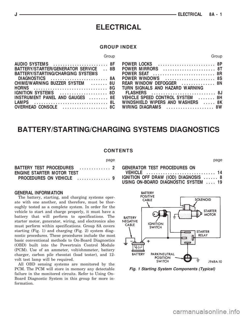
must perform within specifications. Group 8A covers
starting (Fig. 1) and charging (Fig. 2) system diag-
nostic procedures. These procedures include the most
basic conventional methods to On-Board Diagnostics
(OBD) built into the Powertrain Control Module
(PCM). Use of an ammeter, volt/ohmmeter, battery
charger, carbon pile rheostat (load tester), and 12-
volt test lamp will be required.
All OBD sensing systems are monitored by the
PCM. The PCM will store in memory any detectable
failure in the monitored circuits. Refer to Using On-
Board Diagnostic System in this group for more in-
formation.
Fig. 1 Starting System Components (Typical)
JELECTRICAL 8A - 1
Page 281 of 1784
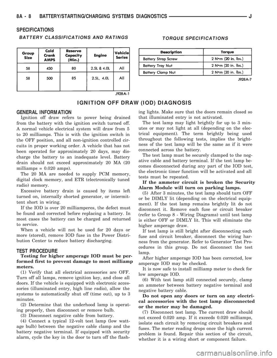
SPECIFICATIONS
IGNITION OFF DRAW (IOD) DIAGNOSIS
GENERAL INFORMATION
Ignition off draw refers to power being drained
from the battery with the ignition switch turned off.
A normal vehicle electrical system will draw from 5
to 20 milliamps. This is with the ignition switch in
the OFF position, and all non-ignition controlled cir-
cuits in proper working order. A vehicle that has not
been operated for approximately 20 days, may dis-
charge the battery to an inadequate level. Battery
drain should not exceed approximately 20 MA (20
milliamps = 0.020 amps).
The 20 MA are needed to supply PCM memory,
digital clock memory, and ETR (electronically tuned
radio) memory.
Excessive battery drain is caused by items left
turned on, internally shorted generator, or intermit-
tent short in wiring.
If the IOD is over 20 milliamperes, the defect must
be found and corrected before replacing a battery. In
most cases the battery can be charged and returned
to service.
When a vehicle will not be used for 20 days or
more (stored), remove IOD fuse in the Power Distri-
bution Center to reduce battery discharging.
TEST PROCEDURE
Testing for higher amperage IOD must be per-
formed first to prevent damage to most milliamp
meters.
(1) Verify that all electrical accessories are OFF.
Turn off all lamps, remove ignition key, and close all
doors. If the vehicle is equipped with electronic acces-
sories (illuminated entry, high line radio), allow the
systems to automatically shut off (time out), up to 3
minutes.
(2) Determine that the underhood lamp is operat-
ing properly, then disconnect or remove bulb.
(3) Disconnect negative cable from battery.
(4) Connect a typical 12-volt test lamp (low watt-
age bulb) between the negative cable clamp and the
battery negative terminal. If equipped with security
alarm, cycle the key in the door to turn off the flash-ing lights. Make sure that the doors remain closed so
that illuminated entry is not activated.
The test lamp may light brightly for up to 3 min-
utes or may not light at all (depending on the elec-
trical equipment). The term brightly being used
throughout the following tests, implies the bright-
ness of the test lamp will be the same as if it were
connected across the battery.
The test lamp must be securely clamped to the neg-
ative cable and battery terminal. If the test lamp be-
comes disconnected during any part of the IOD test,
the electronic timer function will be activated and all
tests must be repeated.
If the ammeter circuit is broken the Security
Alarm Module will turn on parking lamps.
(5) After 3 minutes, the test lamp should turn OFF
or be DIMLY lit (depending on the electrical equip-
ment). If the test lamp remains brightly lit do not
disconnect it. Remove each fuse or circuit breaker
(refer to Group 8 - Wiring Diagrams) until test lamp
is either OFF or DIMLY lit. This will eliminate the
higher amperage draw.
If test lamp is still bright after disconnecting each
fuse and circuit breaker, disconnect the wiring har-
ness from the generator. Refer to Generator Test Pro-
cedures in this group. Do not disconnect the test
lamp.
After higher amperage IOD has been corrected, low
amperage IOD may be checked.
It is now safe to install milliamp meter to check for
low amperage IOD.
(6) With test lamp still connected securely, clamp
an ammeter between battery negative terminal and
negative battery cable.
Do not open any doors or turn on any electri-
cal accessories with the test lamp disconnected
or the meter may be damaged.
(7) Disconnect test lamp. The current draw should
not exceed 0.020 amp. If it exceeds 0.020 milliamps,
isolate each circuit by removing circuit breakers and
fuses. The meter reading drops once the high current
problem is found. Repair this section of the circuit,
whether it is a wiring short or component failure.
BATTERY CLASSIFICATIONS AND RATINGSTORQUE SPECIFICATIONS
8A - 8 BATTERY/STARTING/CHARGING SYSTEMS DIAGNOSTICSJ
Page 321 of 1784

DIAGNOSTICS/SERVICE PROCEDURES
INDEX
page page
Automatic Shut Down (ASD) Relay............ 8
Camshaft Position Sensor Test............... 8
Crankshaft Position Sensor Test.............. 9
Distributor Cap........................... 9
Distributor Rotor......................... 10
DRB Scan Tool.......................... 10
Engine Coolant Temperature Sensor Test...... 12
General Information........................ 8
Ignition Coil............................. 11
Ignition Secondary Circuit Diagnosis.......... 12Ignition Timing........................... 14
Intake Manifold Air Temperature Sensor Test . . . 14
Manifold Absolute Pressure (MAP) Sensor Test . 14
On-Board Diagnostics (OBD)................ 19
Oxygen Sensor Tests..................... 19
Powertrain Control Module (PCM)............ 15
Spark Plug Secondary Cables............... 17
Spark Plugs............................ 16
Throttle Position Sensor Test............... 18
GENERAL INFORMATION
This section of the group, Diagnostics/Service Pro-
cedures, will discuss basic ignition system diagnos-
tics and service adjustments.
For system operation and component identification,
refer to the Component Identification/System Opera-
tion section of this group.
For removal or installation of ignition system com-
ponents, refer to the Component Removal/Installa-
tion section of this group.
For other useful information, refer to On-Board Di-
agnostics in the General Diagnosis sections of Group
14, Fuel System in this manual.
For operation of the DRB Scan Tool, refer to the
appropriate Powertrain Diagnostic Procedures ser-
vice manual.
AUTOMATIC SHUT DOWN (ASD) RELAY
Refer to RelaysÐOperation/Testing in the Group
14, Fuel System section of this service manual.
CAMSHAFT POSITION SENSOR TEST
The camshaft position sensor is located in the dis-
tributor on all engines.
To perform a complete test of this sensor and its
circuitry, refer to the DRB scan tool. Also refer to the
appropriate Powertrain Diagnostics Procedures man-
ual. To test the sensor only, refer to the following:
2.5L OR 4.0L ENGINE
For this test, an analog voltmeter is needed.Do
not remove the distributor connector from the dis-
tributor. Using small paper clips, insert them into
the backside of the distributor wire harness connec-
tor to make contact with the terminals. Be sure that
the connector is not damaged when inserting the pa-
per clips. Attach voltmeter leads to these paper clips.
(1) Connect the positive (+) voltmeter lead into
the sensor output wire. This is at done the distribu-
tor wire harness connector. For wire identification,
refer to Group 8W, Wiring Diagrams.(2) Connect the negative (-) voltmeter lead into the
ground wire. For wire identification, refer to Group
8W, Wiring Diagrams.
(3) Set the voltmeter to the 15 Volt DC scale.
(4) Remove distributor cap. Rotate (crank) engine
with starter until pulse ring (Fig. 1) enters the mag-
netic pickup on camshaft position sensor. Distributor
rotor should be pointed in 9 o'clock position. The
movable pulse ring should now be within the sensor
pickup.
(5) Turn ignition key to ON position. Voltmeter
should read approximately 5.0 volts.
(6) If voltage is not present, check the voltmeter
leads for a good connection.
(7) If voltage is still not present, check for voltage
at the supply wire. For wire identification, refer to
Group 8W, Wiring Diagrams.
Fig. 1 Pulse Ring/Rotor PositionÐTypical
8D - 8 IGNITION SYSTEMSJ
Page 323 of 1784
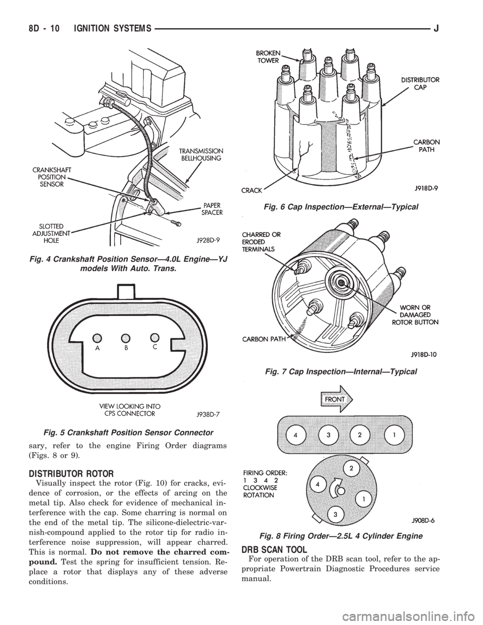
sary, refer to the engine Firing Order diagrams
(Figs. 8 or 9).
DISTRIBUTOR ROTOR
Visually inspect the rotor (Fig. 10) for cracks, evi-
dence of corrosion, or the effects of arcing on the
metal tip. Also check for evidence of mechanical in-
terference with the cap. Some charring is normal on
the end of the metal tip. The silicone-dielectric-var-
nish-compound applied to the rotor tip for radio in-
terference noise suppression, will appear charred.
This is normal.Do not remove the charred com-
pound.Test the spring for insufficient tension. Re-
place a rotor that displays any of these adverse
conditions.
DRB SCAN TOOL
For operation of the DRB scan tool, refer to the ap-
propriate Powertrain Diagnostic Procedures service
manual.
Fig. 4 Crankshaft Position SensorÐ4.0L EngineÐYJ
models With Auto. Trans.
Fig. 5 Crankshaft Position Sensor Connector
Fig. 6 Cap InspectionÐExternalÐTypical
Fig. 7 Cap InspectionÐInternalÐTypical
Fig. 8 Firing OrderÐ2.5L 4 Cylinder Engine
8D - 10 IGNITION SYSTEMSJ
Page 376 of 1784
AUDIO SYSTEMS
CONTENTS
page page
GENERAL INFORMATION.................. 1
RADIO ANTENNA........................ 8XJ SERVICE PROCEDURES................ 4
YJ SERVICE PROCEDURES................ 6
GENERAL INFORMATION
DESCRIPTION
Each radio receives ignition feed from an ignition
switch controlled fuse. There is an additional in-line
fuse in the back of the radio chassis. The in-line fuse
will blow in the event an internal short occurs.
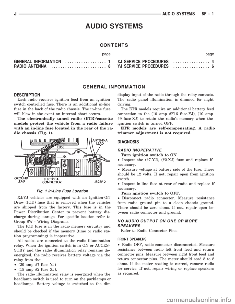
The electronically tuned radio (ETR)/cassette
models protect the vehicle from a radio failure
with an in-line fuse located in the rear of the ra-
dio chassis (Fig. 1).
XJ/YJ vehicles are equipped with an Ignition-Off
Draw (IOD) fuse that is removed when the vehicles
are shipped from the factory. This fuse is in the
Power Distribution Center to prevent battery dis-
charge during storage. For specific location refer to
Group 8W - Wiring Diagrams.
The IOD fuse is in the radio memory circuitry and
should be checked if the memory (time or radio sta-
tion programming) is inoperative.
All radios are connected to the radio illumination
relay. When the ignition switch is in ON or ACCES-
SORY and the radio illumination relay remains de-
energized, the radio receives battery voltage via the
relay from the:
²(20 amp #7 fuse YJ)
²(15 amp #2 fuse XJ).
The radio illumination relay is energized when the
headlamp switch is used to turn on the parklamps or
headlamps. Battery voltage is switched to the dimdisplay input of the radio through the relay contacts.
The radio panel illumination is dimmed for night
driving.
The ETR models require an additional battery feed
connection to the (10 amp #F16 fuse-YJ), (10 amp
#9 fuse-XJ) to retain the radio's memory when the
ignition switch is turned OFF.
ETR models are self-compensating. A radio
trimmer adjustment is not required.
DIAGNOSIS
RADIO INOPERATIVE
Turn ignition switch to ON
²Inspect the (#7-YJ), (#2-XJ) fuse and replace if
necessary.
²Measure voltage at battery side of the fuse. There
should be 12 volts. If not, repair open from ignition
switch.
²Inspect in-line fuse at rear of radio and replace if
necessary.
Turn ignition switch to OFF.
²Disconnect radio connector. Measure resistance
from radio ground pin to a clean chassis ground.
There should be zero ohms. If not, repair open be-
tween radio connector and ground.
NO AUDIO OUTPUT ON ONE OR MORE
SPEAKERS
Refer to Radio Connector Pins.
FRONT SPEAKERS
²Radio OFF, radio connector disconnected. Measure
resistance between radio left front feed and return
connector pins. Measure between right front feed and
return connector pins. The meter should read 5 to 8
ohms. If the meter reading is correct, remove radio
for service. If not, repair wiring or replace speakers
as required.
Fig. 1 In-Line Fuse Location
JAUDIO SYSTEMS 8F - 1